RADIO 1 - Supervisor's Desk (LOP 18) & Patch Panels - Click here for details

Rob Flory at Supervisor's Station
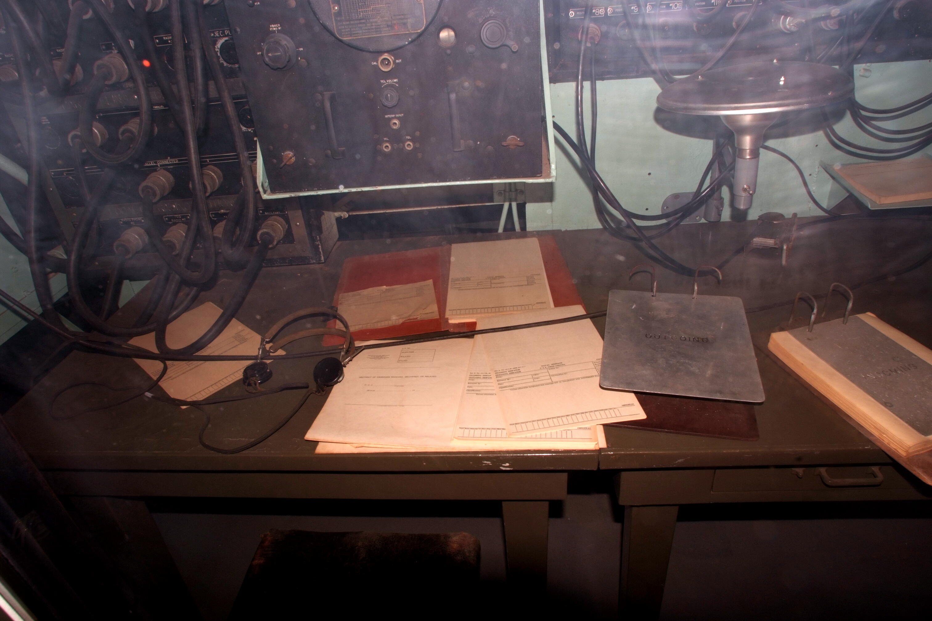
Supervisor's Desk
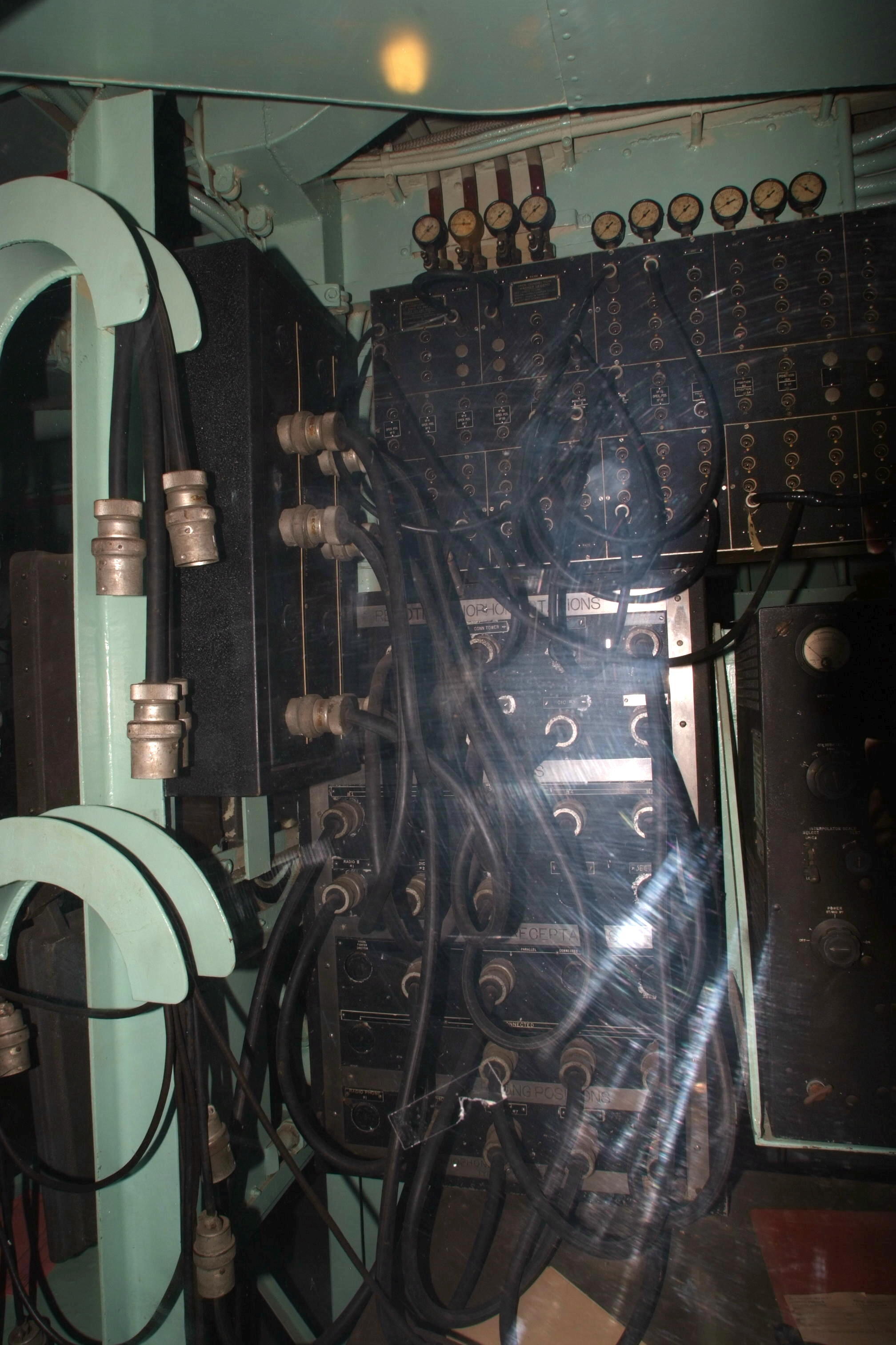
Left - xmtr radiophone parallel jacks
Lower Middle - xmtr radiophone
Upper Middle- rcvr antennas
Click here for patch panel details
Note gauges for pressurized VHF/UHF transmission lines
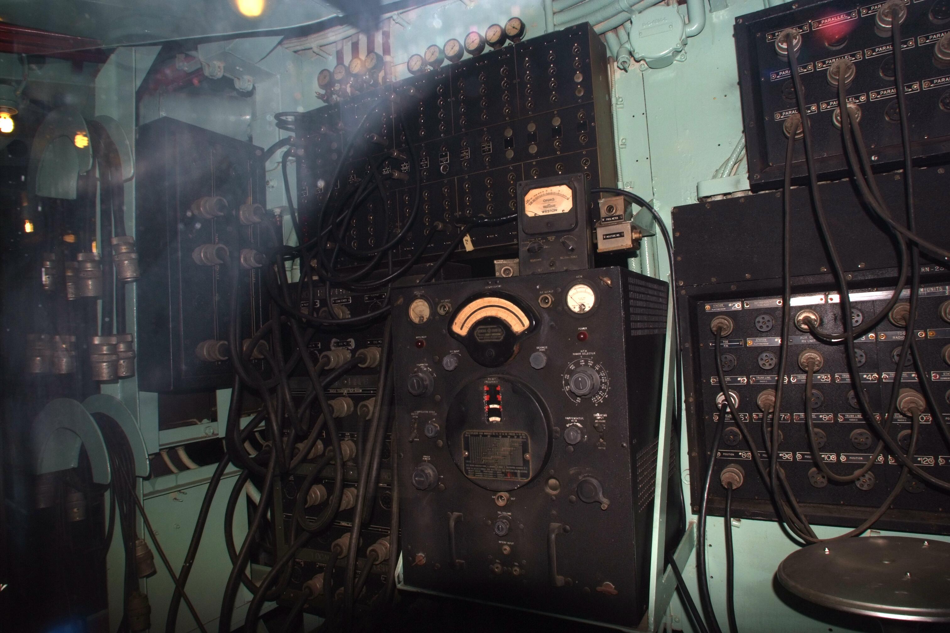
Center- LR freq meter
Right - xmtr key/control
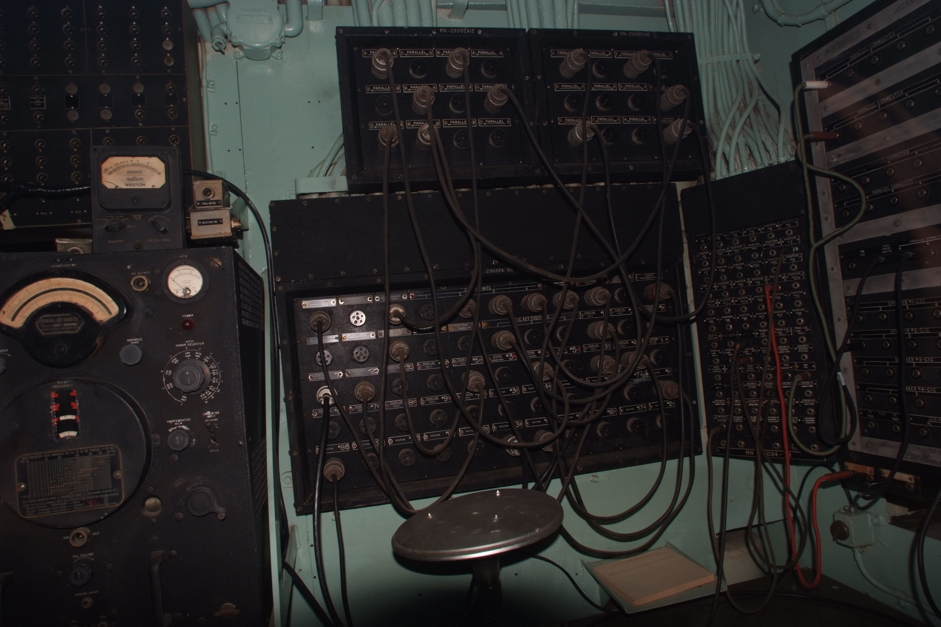
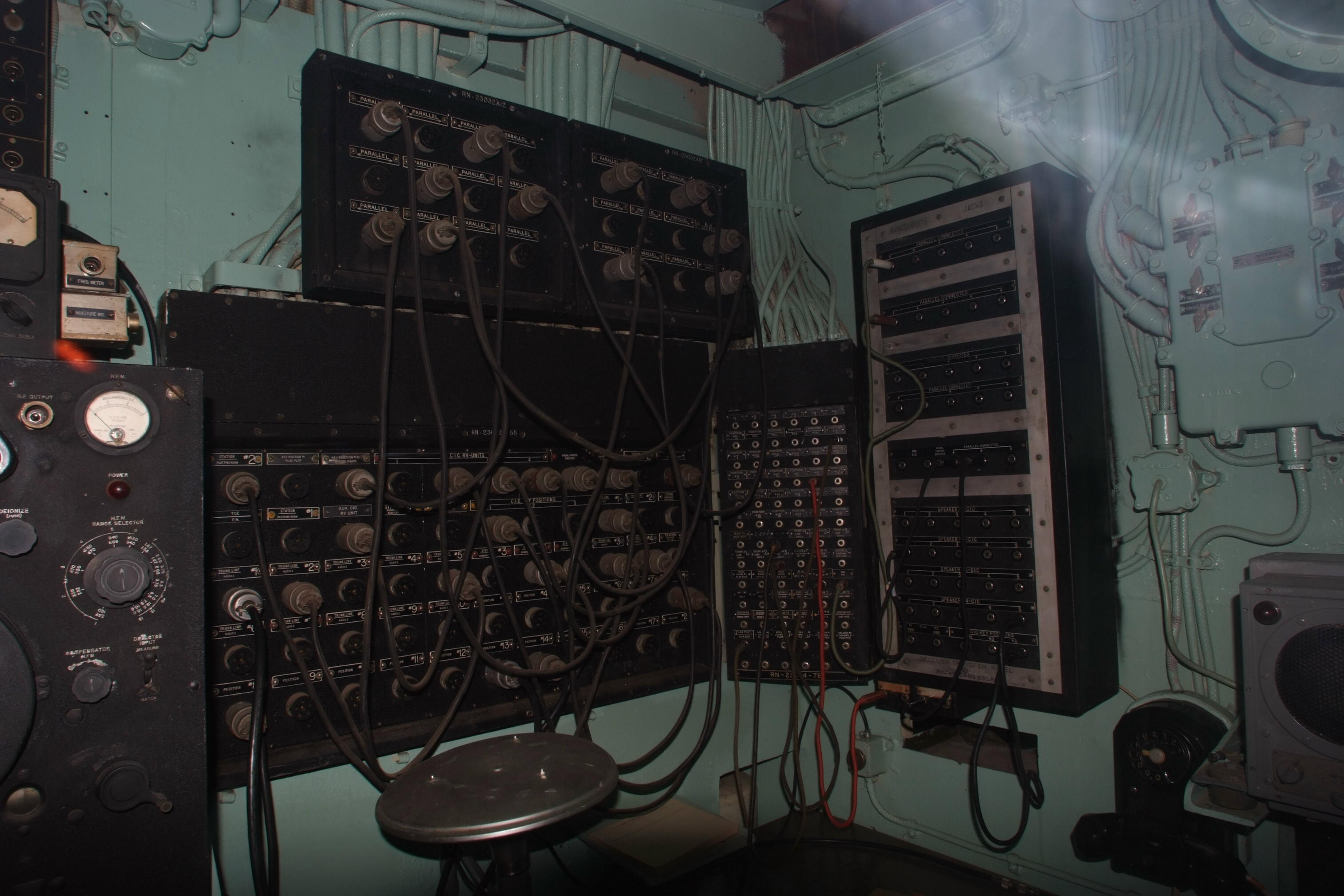
Right side - rcvr audio
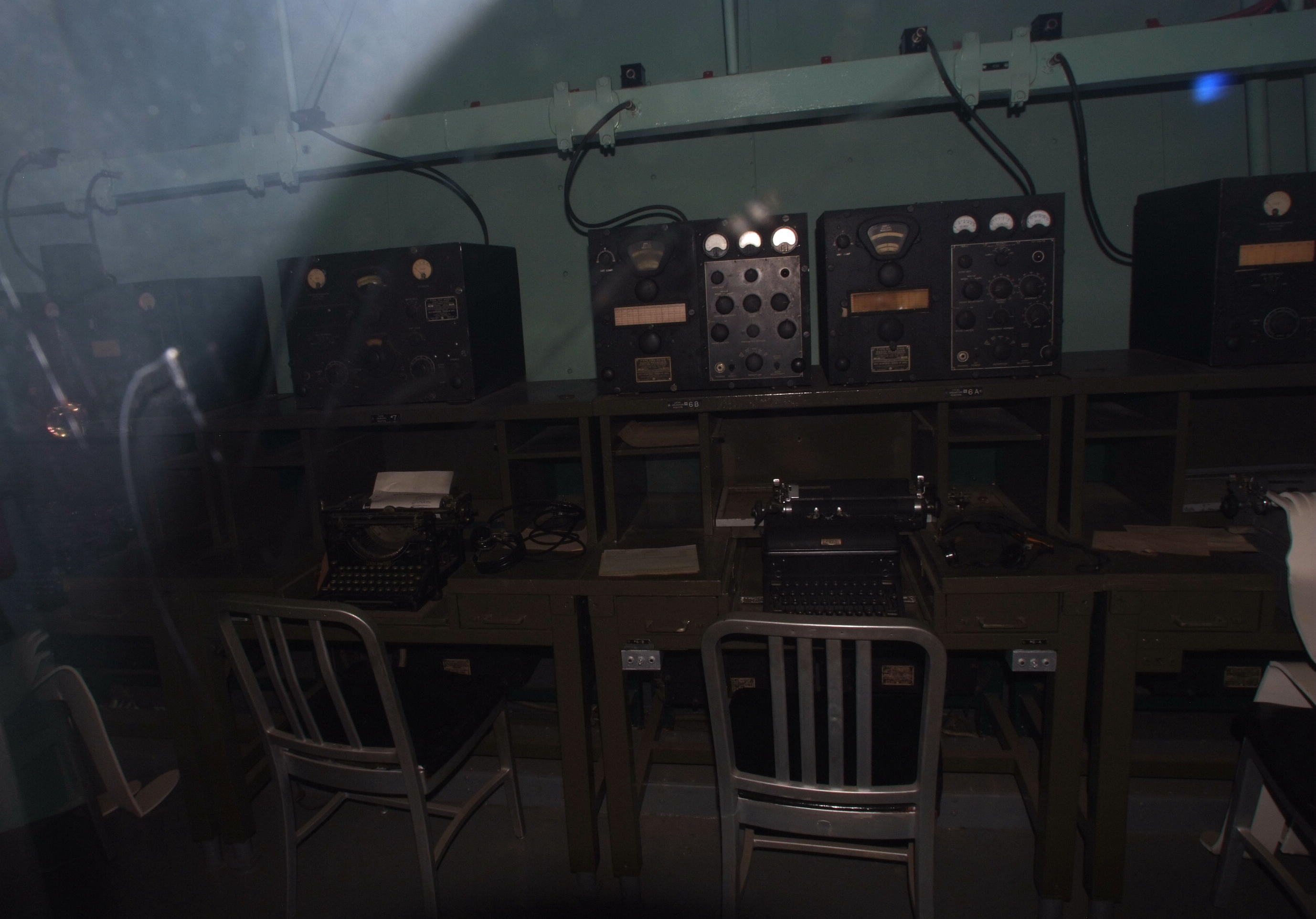
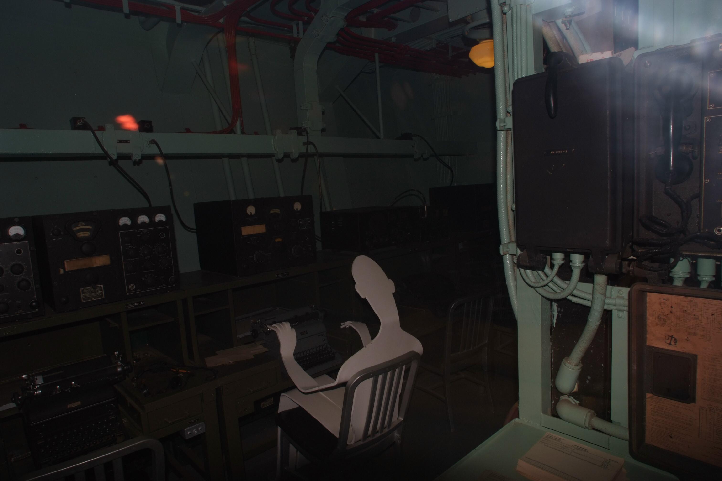
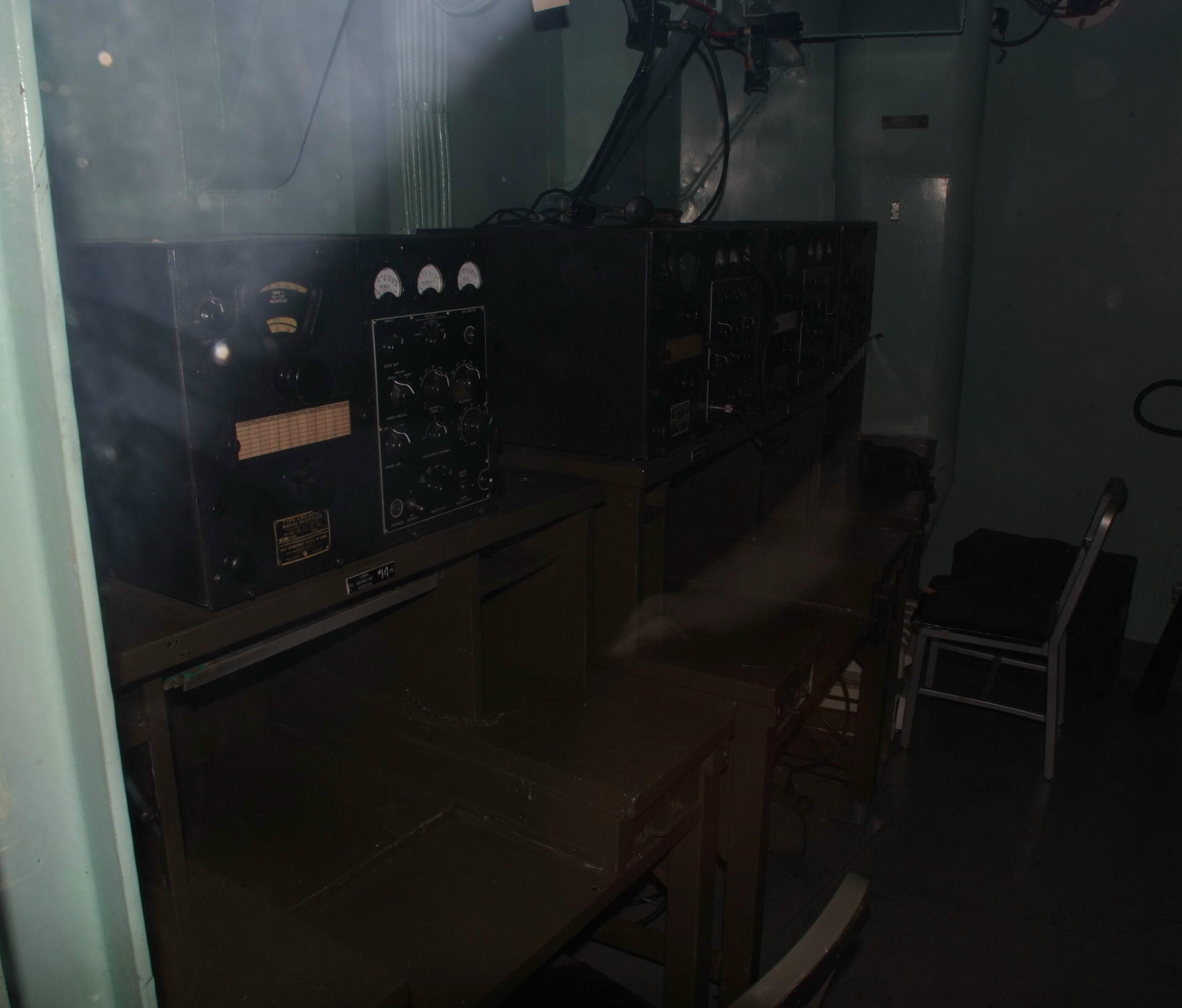
RADIO 1 - Local Operating Positions (LOP)
LOP 1-11 outboard, LOP 12-17 inboard against curved bulkhead (turret 2 barbette)
Outboard bulkhead, in order L to R (forward to aft)

Repair desk with tube tester
LOP 11(RBB-2)
LOP 10 (RBB-2)
LOP 9 (RBC-2)
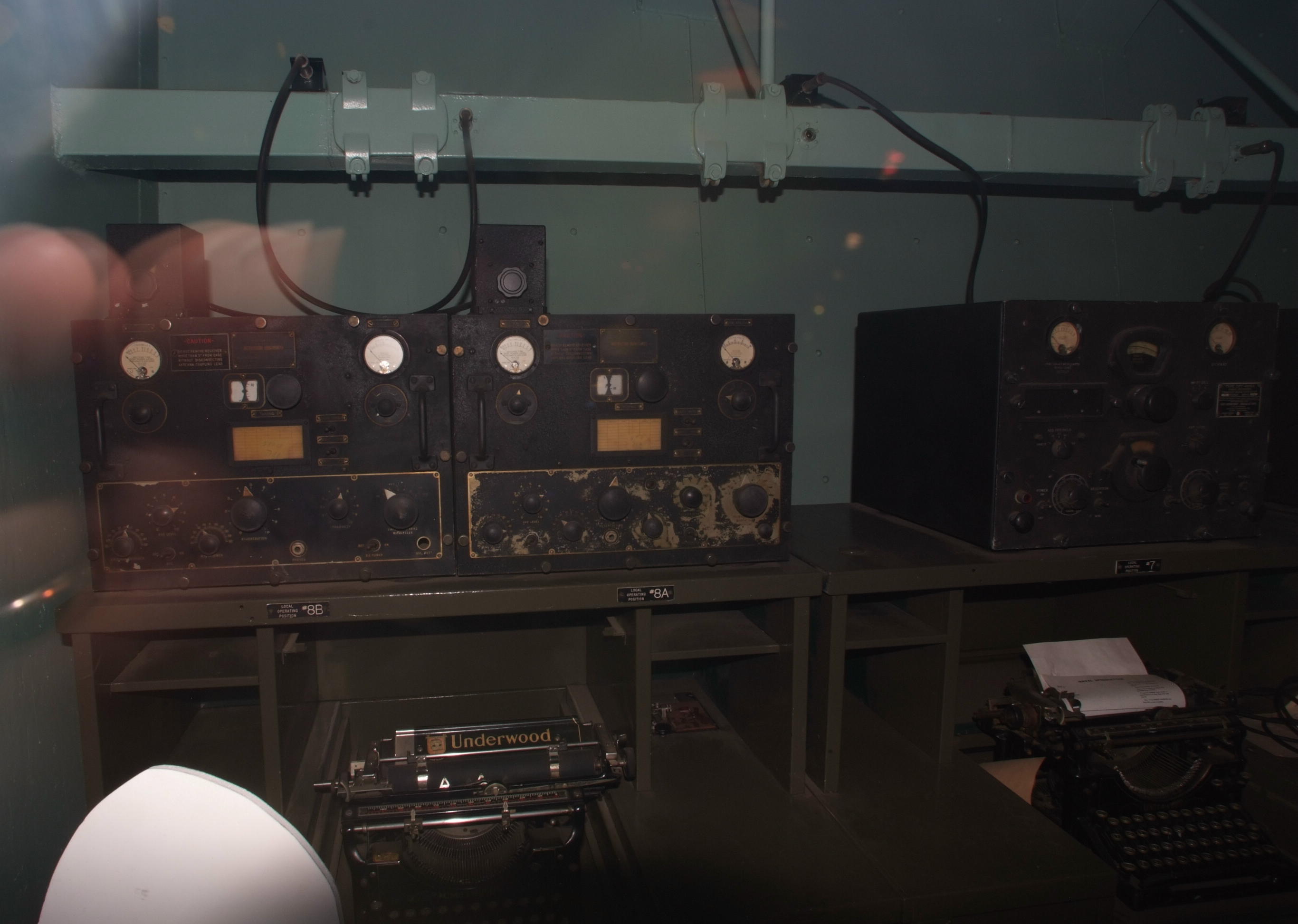
LOP 8 (RAK & RAL)
LOP 7 (RBA-2)
note antenna distribution trunk
LOP 8 (RAK & RAL)
LOP 7 (RBA-2)
LOP 6 (RBB-2 & RBC-2)
note antenna distribution trunk
LOP 6 (RBB-2 & RBC-2)
LOP 5 (RBA-2)
LOP 4 (Hallicrafters S-27)
LOP 3 (rcvr?) No photo yet
LOP 2 (rcvr?) No photo yet
LOP 1 (RBB-2) No photo yet
Inboard bulkhead in order R to L (forward to aft)
LOP 12 (RBC-2)
LOP 13 (RBC-2)
LOP 14 (RBC-2)
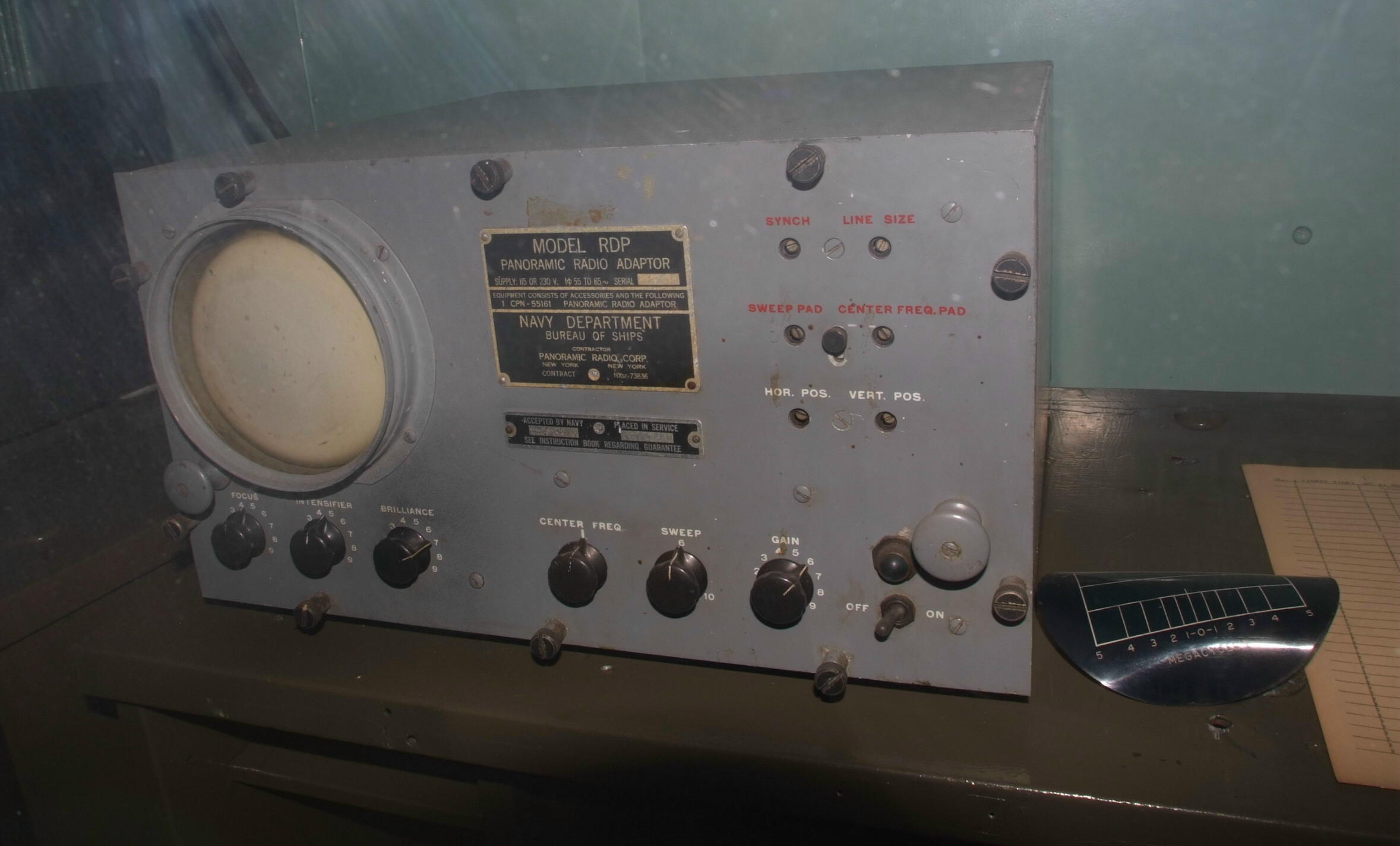
LOP 15 (RBC-2) RDP on display
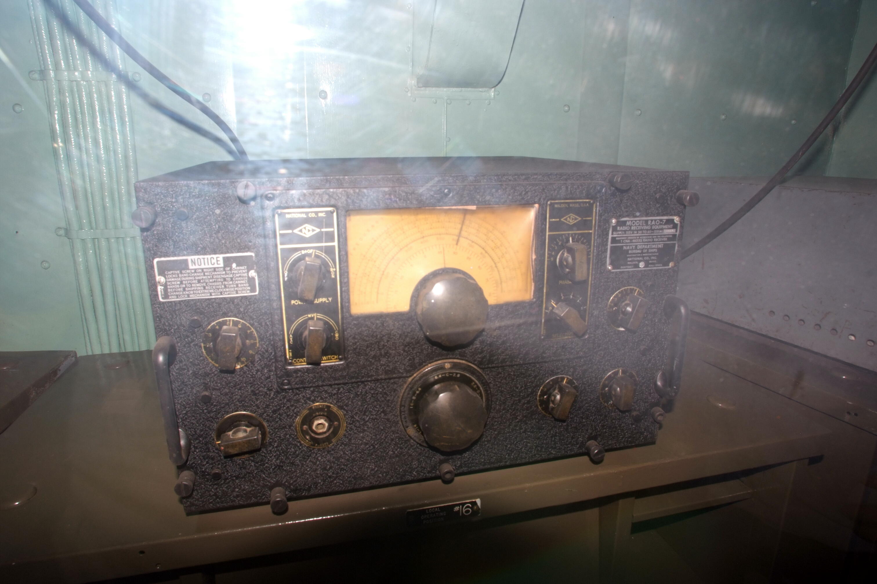
LOP 16 (rcvr?) RAO-7 rcvr on display
LOP 17 (rcvr?) No photo yet
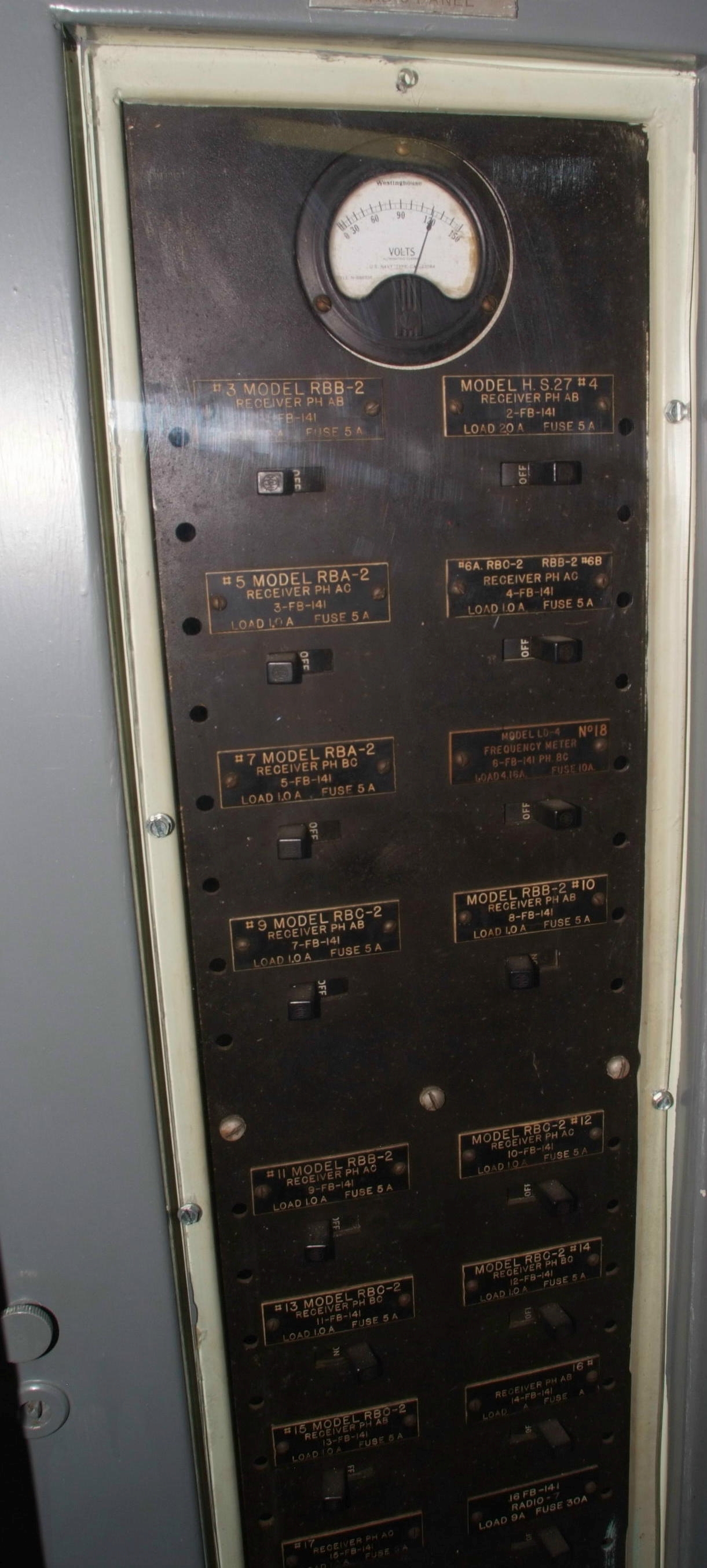
Breaker panel for Radio 1 with equipment labeled - note "Model H.S.27" at Station 4 instead of "RBK"
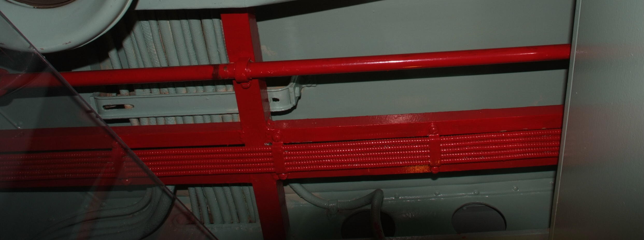
Antenna cables mounted overhead
small flexible type for HF/MF receivers
larger rigid pressurized type for VHF/UHF

Radio 1 - phones and antenna cables
Miscellaneous to be sorted later
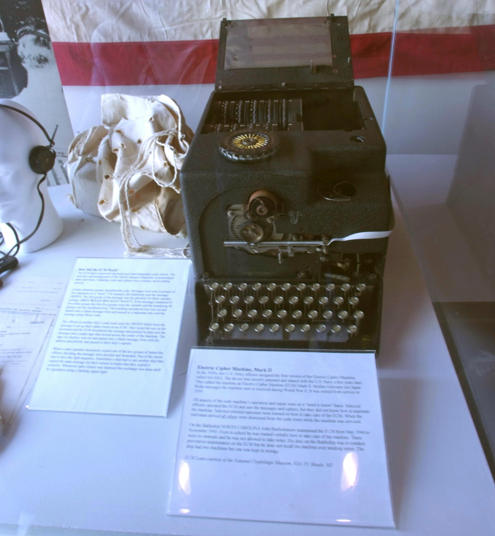
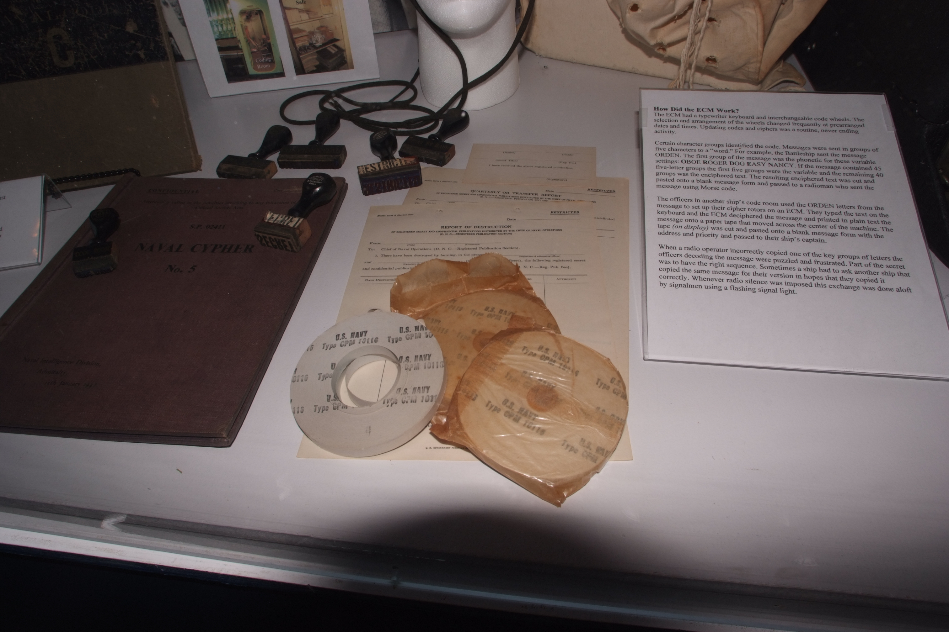
ECM coding machine display - BB55 museum label says:
"Electric Cipher Machine, Mark II
In the 1930s, two U.S. Army officers designed the first version of the Electric Cipher Machine, called SIGABA. The device was secretly patented and shared with the U.S. Navy a few years later. They called the machine an Electric Cipher Machine (ECM) Mark II. Neither Germany nor Japan broke messages the machine sent or received during World War II. It was retired from service in 1959.
All aspects of the code machine’s operation and repair were on a “need to know” basis. Selected officers operated the ECM and saw the messages and ciphers, but they did not know how to maintain the machine. Selected enlisted radiomen were trained on how to take care of the ECM. When the radioman arrived all others were dismissed from the code room while the machine was serviced.
ECM Loan courtesy of the National Cryptologic Museum, NSA, Ft. Meade, MD"
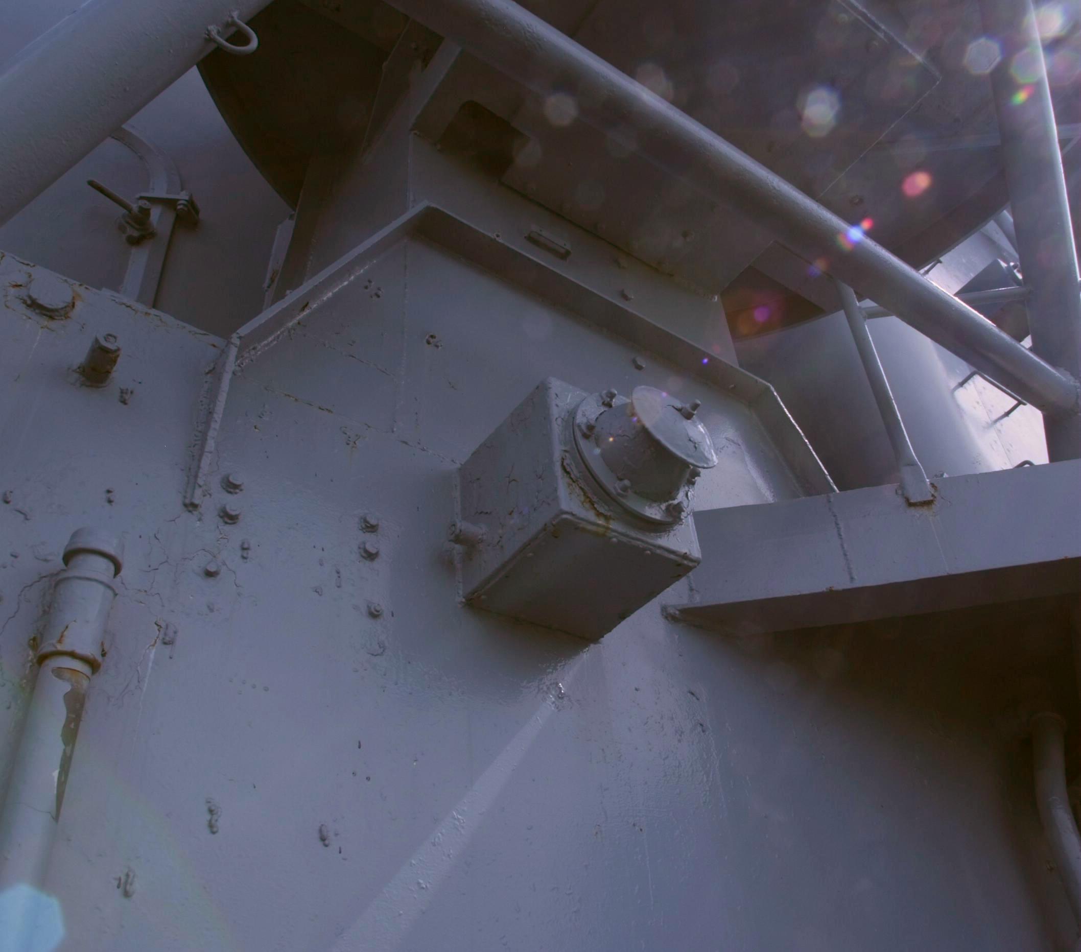
Antenna insulator - receiving antenna?

MAN (VHF-FM) control in CIC