Navy Tape & Automatic Relay Centers
- I really enjoyed reading this short novel about life in a Torn Tape Relay (NAVCOMMSTA Philippines Vietnam era).
It seems like a well-written authentic story portraying the constant workload in a major relay and fleet support center.
It's a quick (71 pages) but very interesting read
|
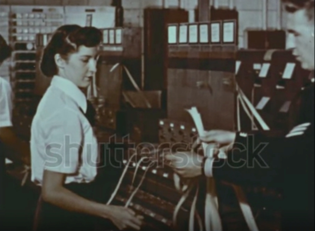
OPERATOR TRAINING
SEND OPERATOR.-See that your new operator carefully removes tape from grid, keeping it off the floor. A dirty tape
can cause garbles. Make sure he selects tapes from the washboard within precedence groups in proper order. See that he
checks routing indicator before inserting tape under transmitter lid. Entries in his sent traffic log must be complete - incoming
channel designator and message number, routing indicator of addressee, and operator's sign. Check the log
frequently.
RECEIVE OPERATOR.-A receive operator's timely entries in the received numbers sheet can prevent duplicated or omitted
numbers. Make sure your new operator at this position logs his· entries correctly and on the spot. He must check each
tape's channel number and cross that number off the sheet. See if your receive operator can spot garbled or mutilated
tapes: A correction here may save a time-consuming station-to-station service.
TAPE FACTORY OPERATOR.-A new man should be thoroughly indoctrinated in tape relay routing procedure before he
takes over as tape factory operator. When he does take over, he should keep posted on the latest routing changes. Make
certain he has an up-to-date channel routing guide at his fingertips for immediate reference. Check each tape as your
new operator circles the indicators to make sure he has not omitted addressees and that none have been duplicated in the
routing. You may catch a misroute here. Glance at the tape factory log frequently. Does each indicator have a line drawn
through it and an operator's sign opposite the routing line? See if your new man is alert for garbled or otherwise doubtful
indicators. Make sure he turns these over to the service clerk for proper action.
|
NAVCOMMSTA Hawaii 1948
|
Video
of torn tape relay operation - circa 1953 - Washington

|
82B-1 system - Cheltenham 1959

|
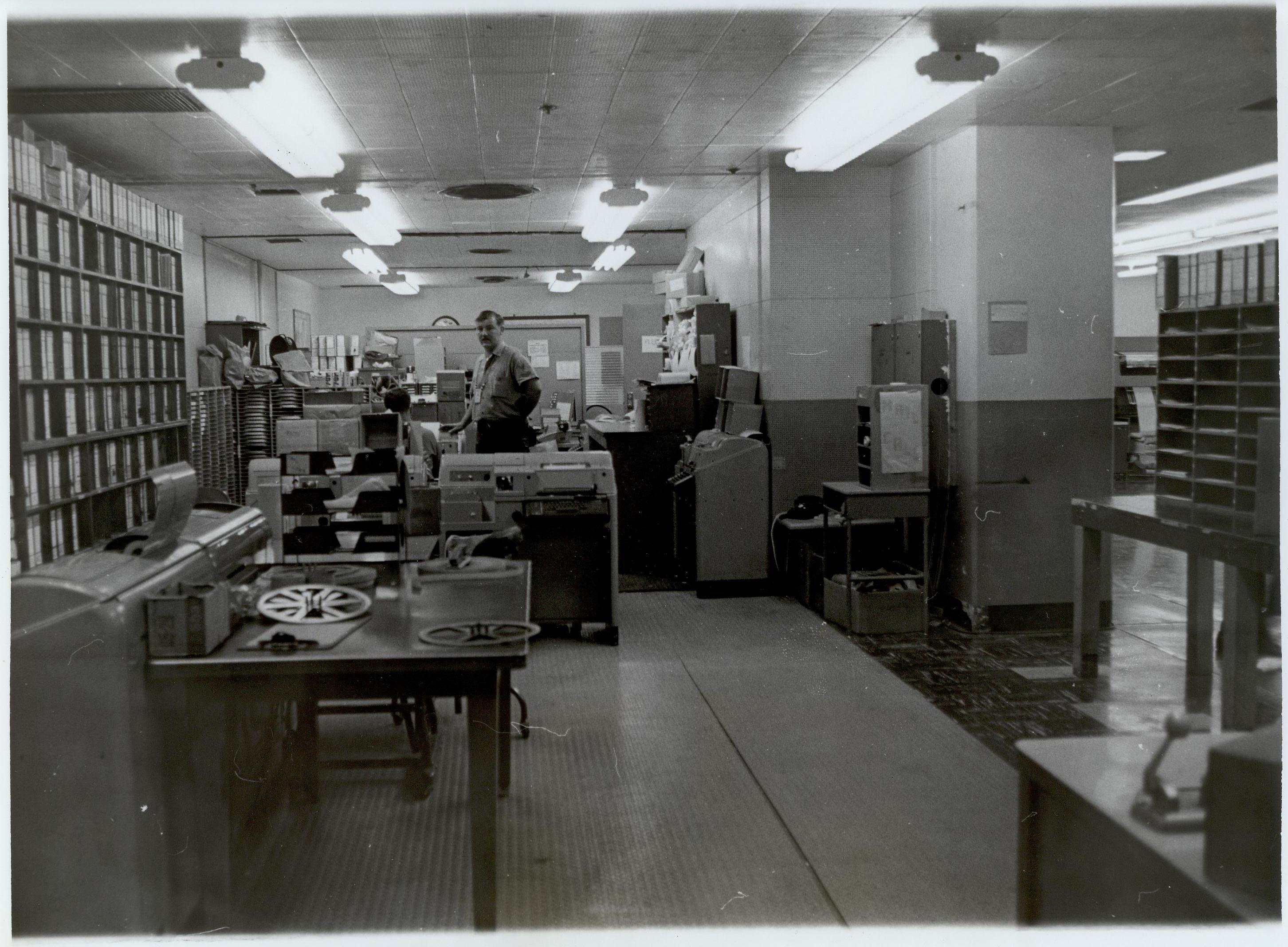
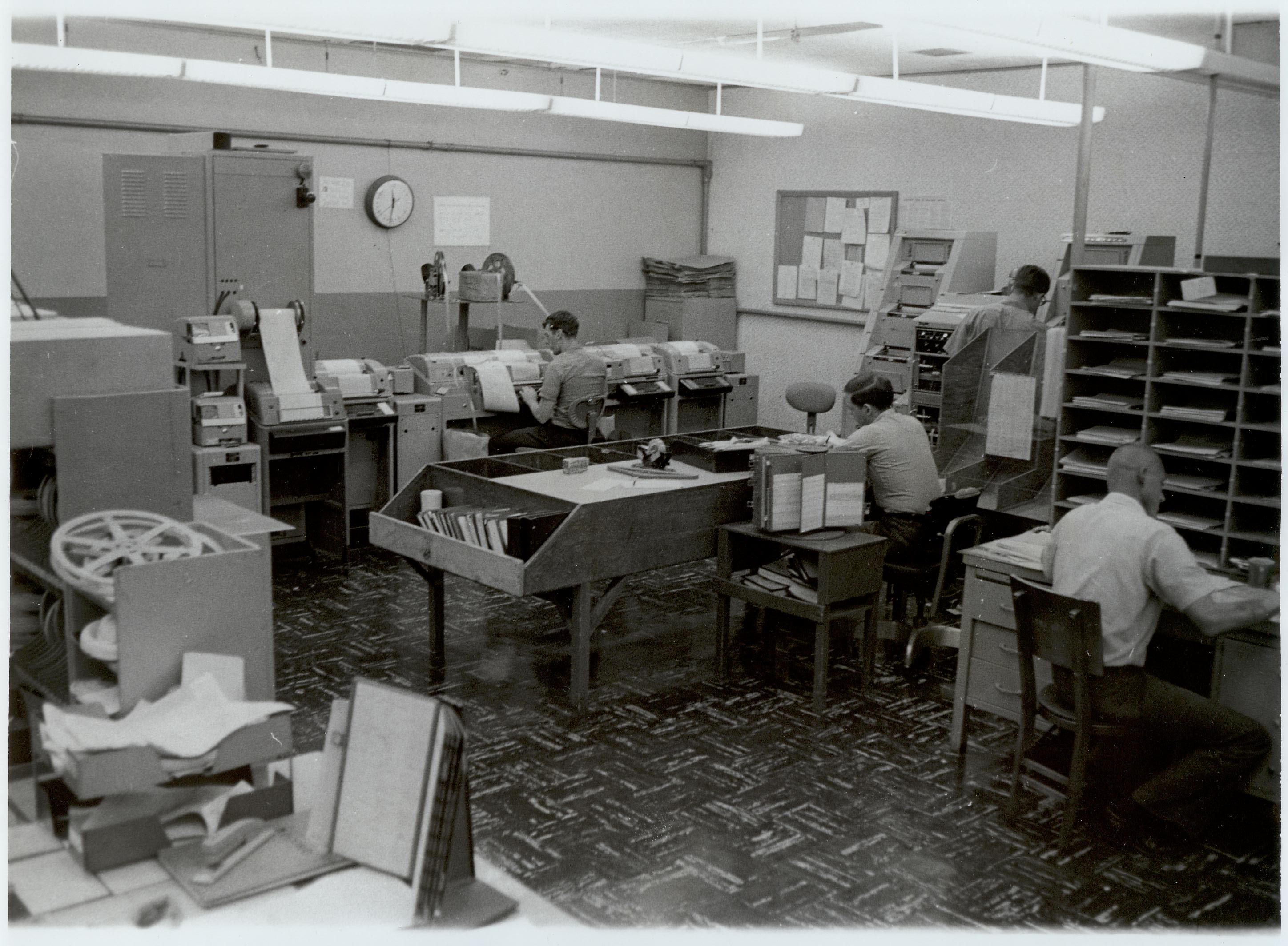
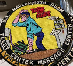
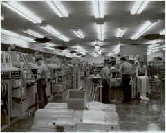
Guam - 1968
 |
| NAVCOMMSTA GUAM 1968-69 - photos thanks to Rodney Rood
& George Overman |
|

|
|
 |
 |
|
|
|
 |
|
|
 |
 |
|
|
 |
 |
|
|
 |
|
|
|
 |
 |
|
|
 |
 |

|
|
 |
| -- |
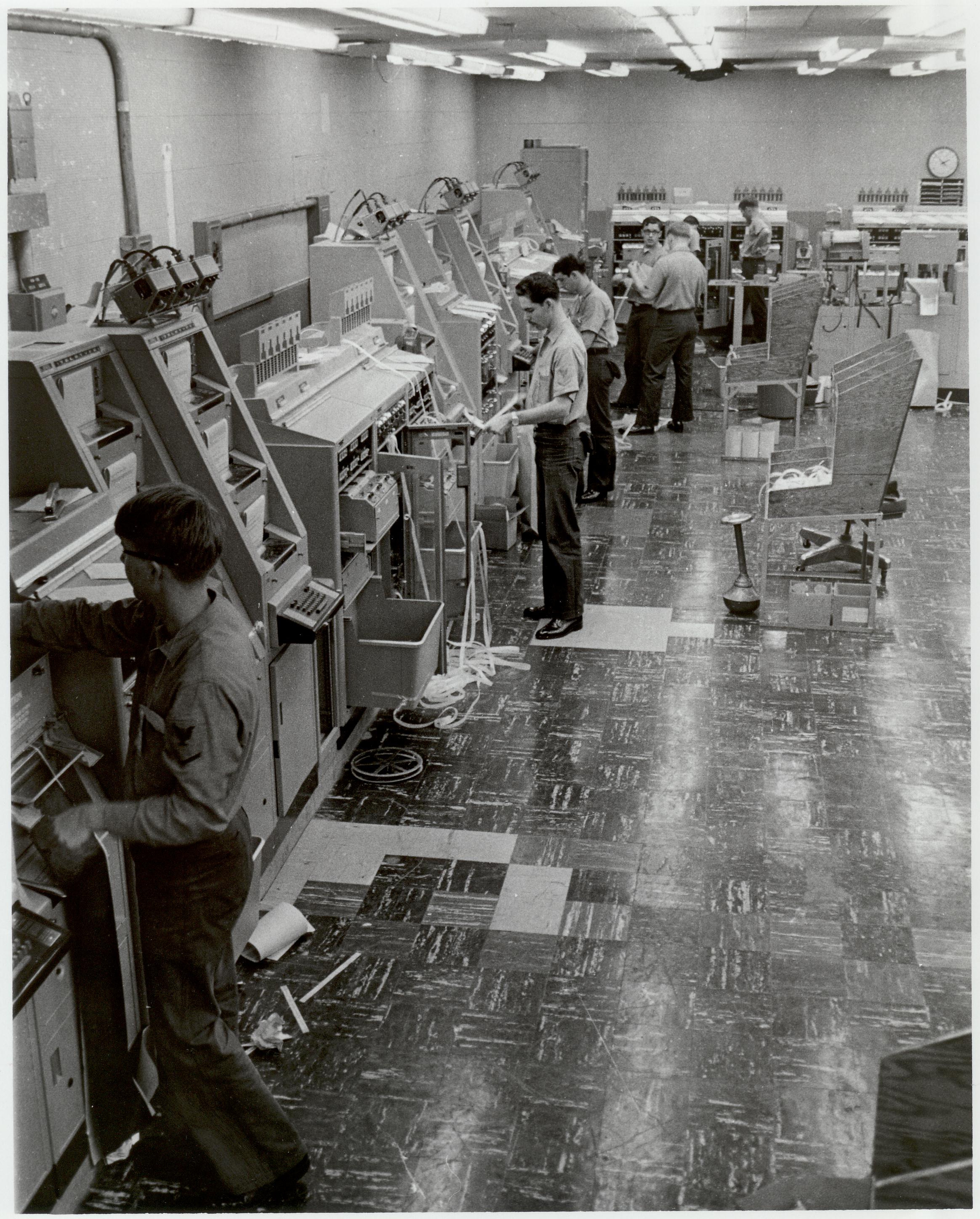
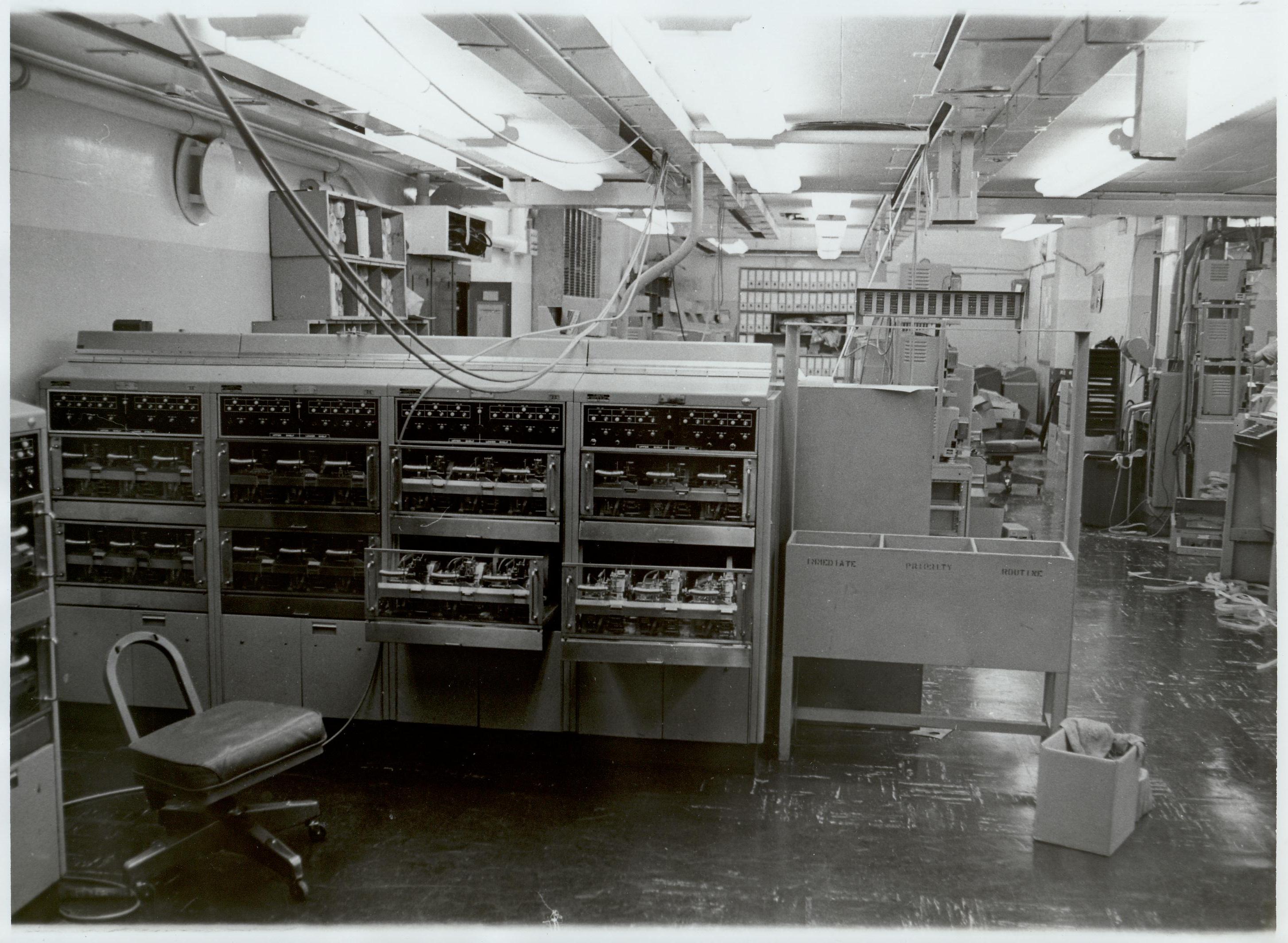
| TAPE RELAY EQUIPMENTS (1962)
The volume of teletypewriter traffic relayed by NAVCOMMSTAs and many of the smaller shore stations has led to the development of tape relay equipment that requires a minimum of operator attention.
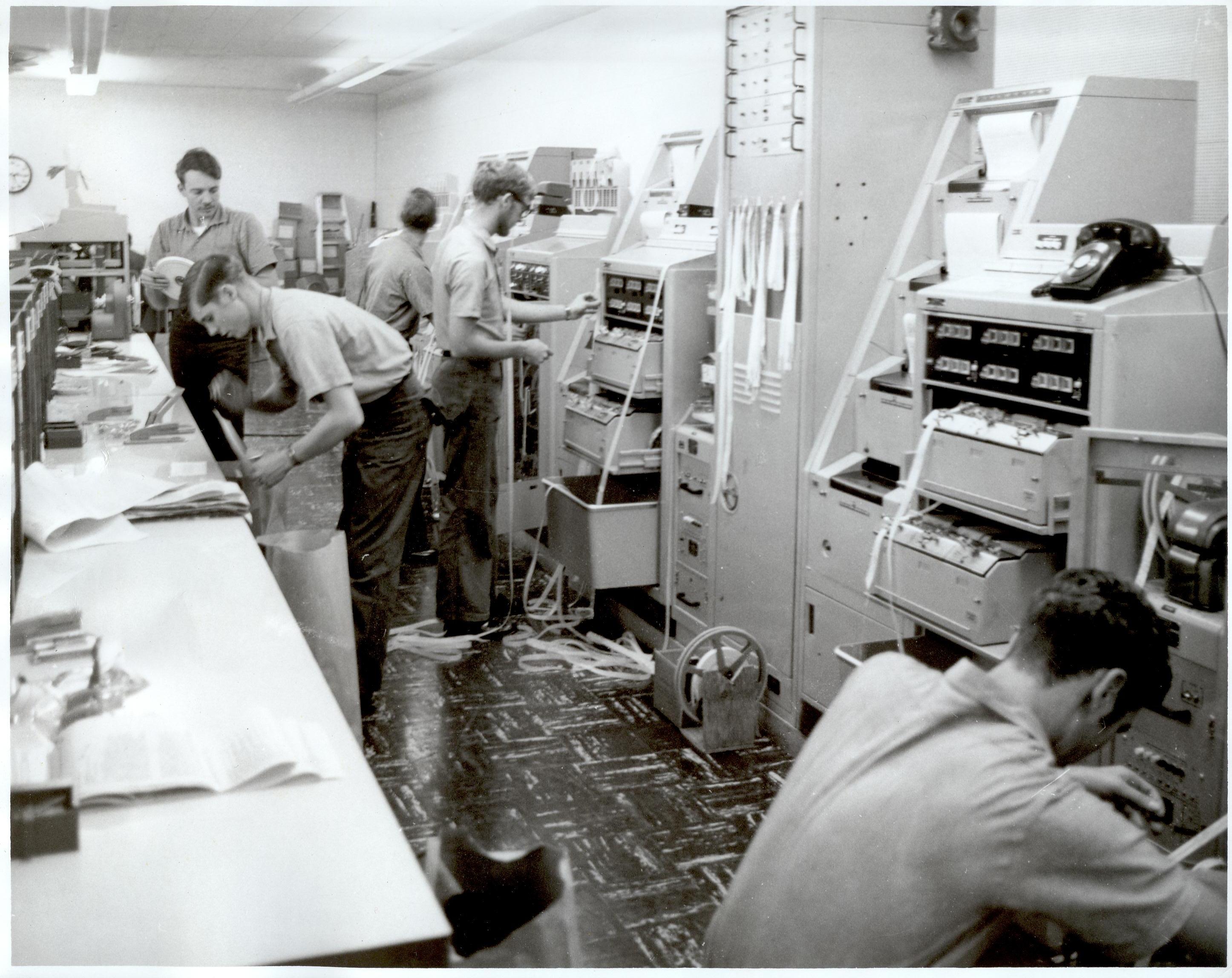
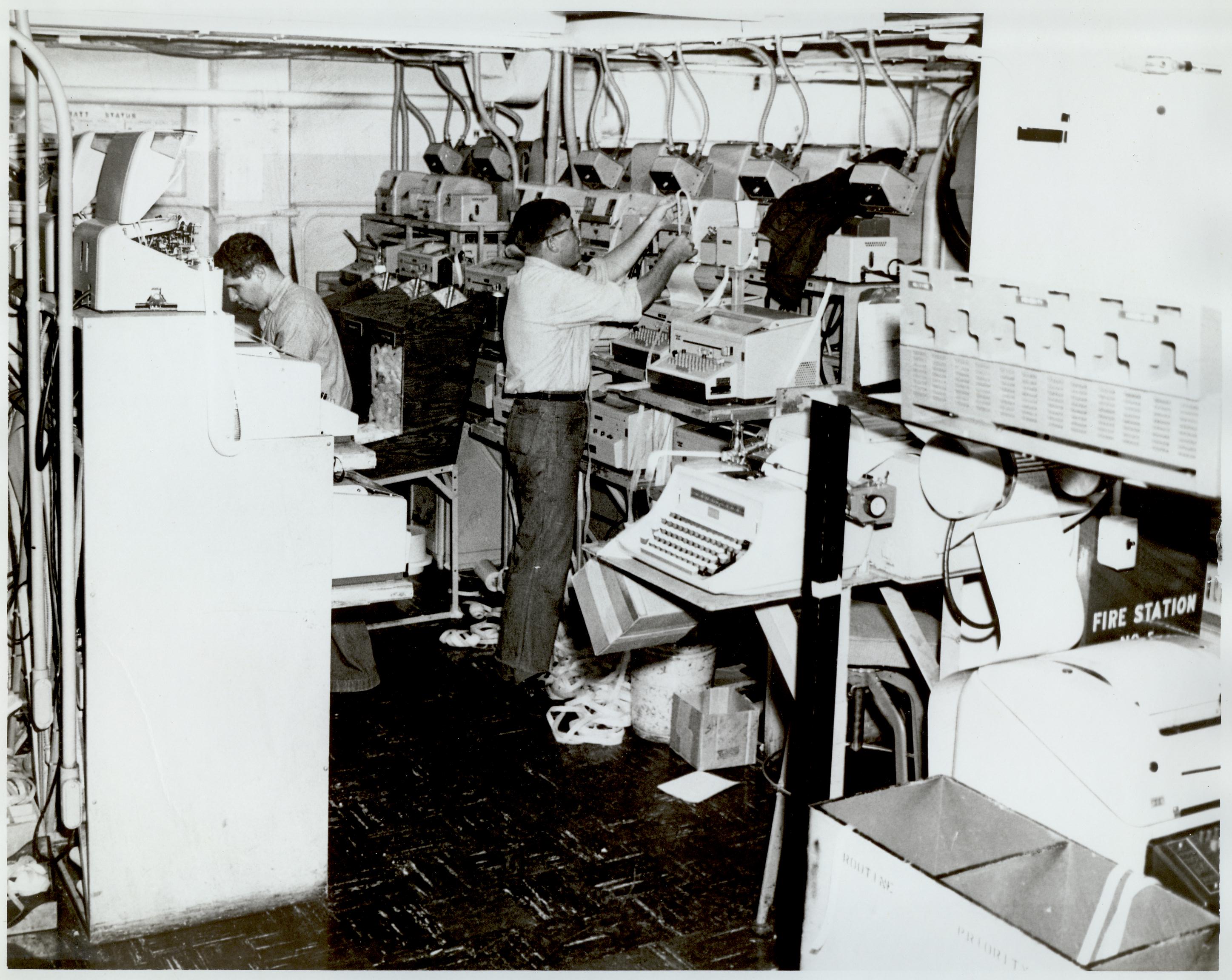
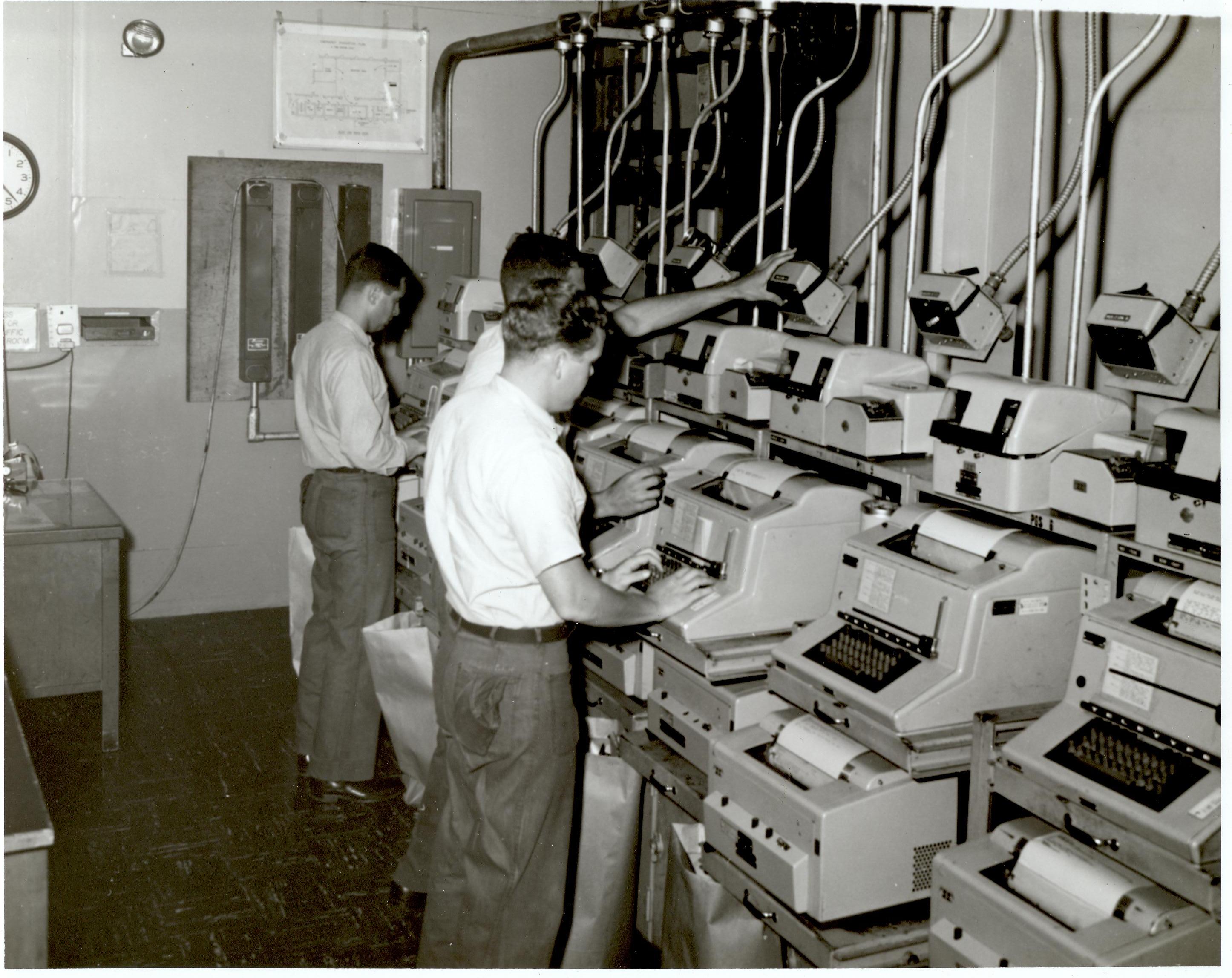
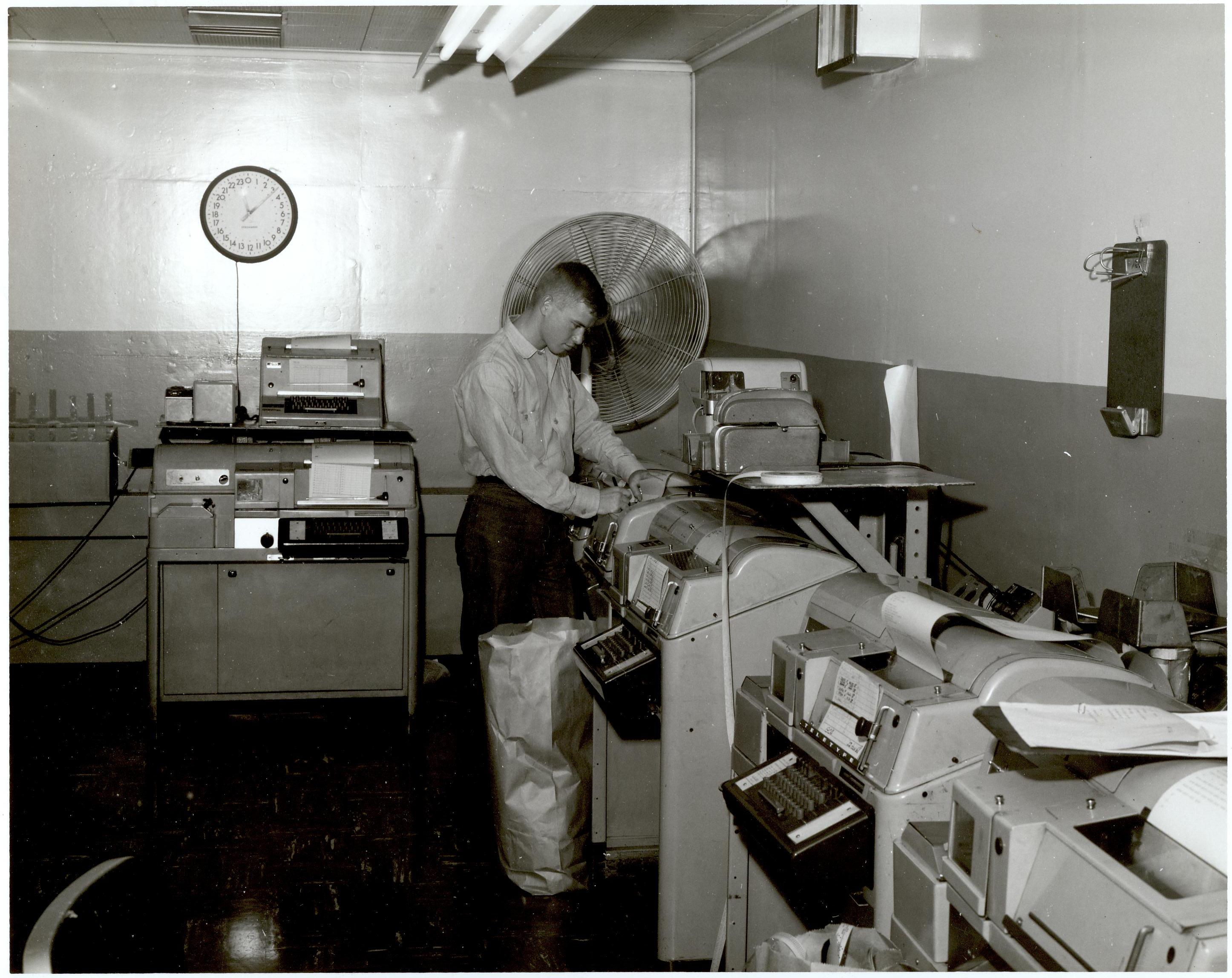
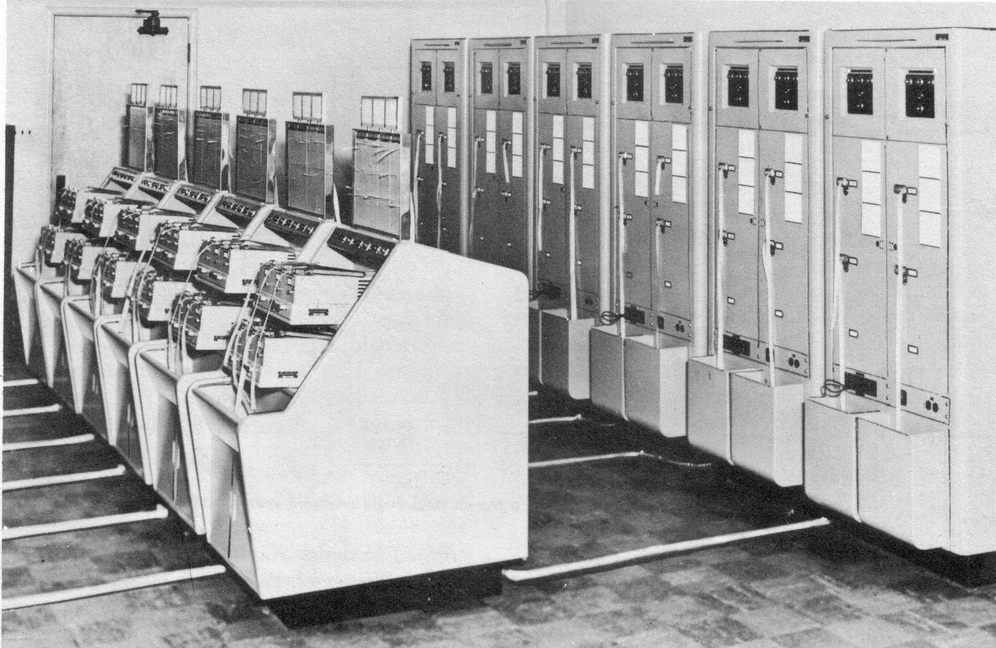
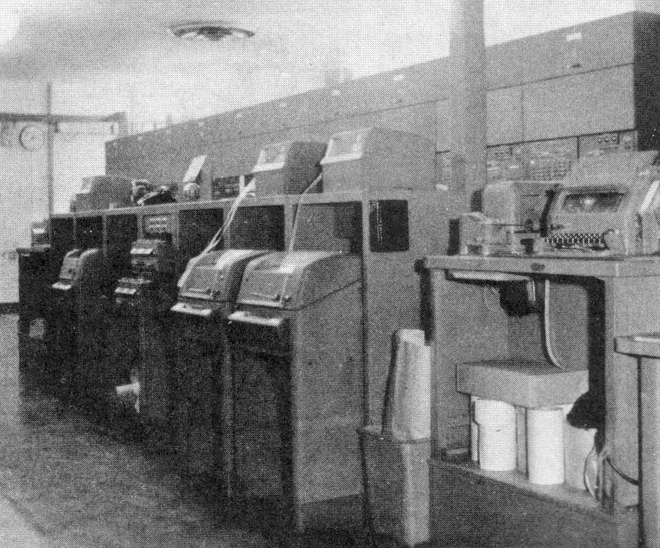
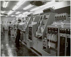
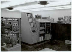
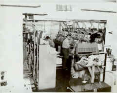
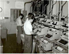
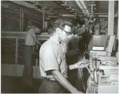
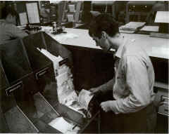
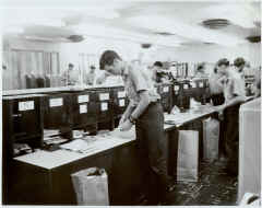
In figure 1 below are receiving banks or console packages, which house several typing
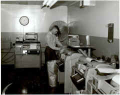
reperforators for use on incoming lines in torn-tape relay centers. The operator logs each incoming message, tears it off at the end of the message, and determines the proper outgoing circuit from the routing indicators on the tape. He then hand-carries each tape to the appropriate sending bank of automatic transmitter-distributors
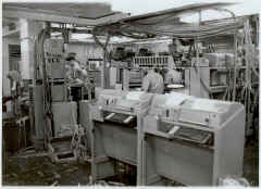
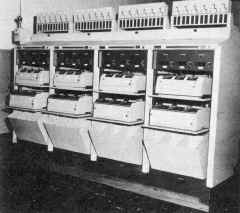
(fig. 2 below), and inserts it in the appropriate circuit tape grid (visible at tops of sending banks). The tape grid - sometimes called a washboard owing to a certain similarity of appearance - is simply a place where tapes can remain during the period they are awaiting retransmission. They are stowed from top down in order of precedence. Other operators in attendance at the sending bank remove waiting tapes from the grid in order of precedence, and insert them in the
TD's. A numbering TD applies a sequential channel number to each message, thus keeping a record of traffic relayed over each channel.
If duplicate copies of relayed traffic are required for the files, monitoring equipment (not shown in fig. 7-32) is used. This is a group of typing reperforators which produces duplicates of tapes undergoing transmission on the sending bank, and winds the monitor tapes on reels suitable for stowage. The monitoring equipment also duplicates the channel number for each message, providing a means of reference should the message be needed in the future. |
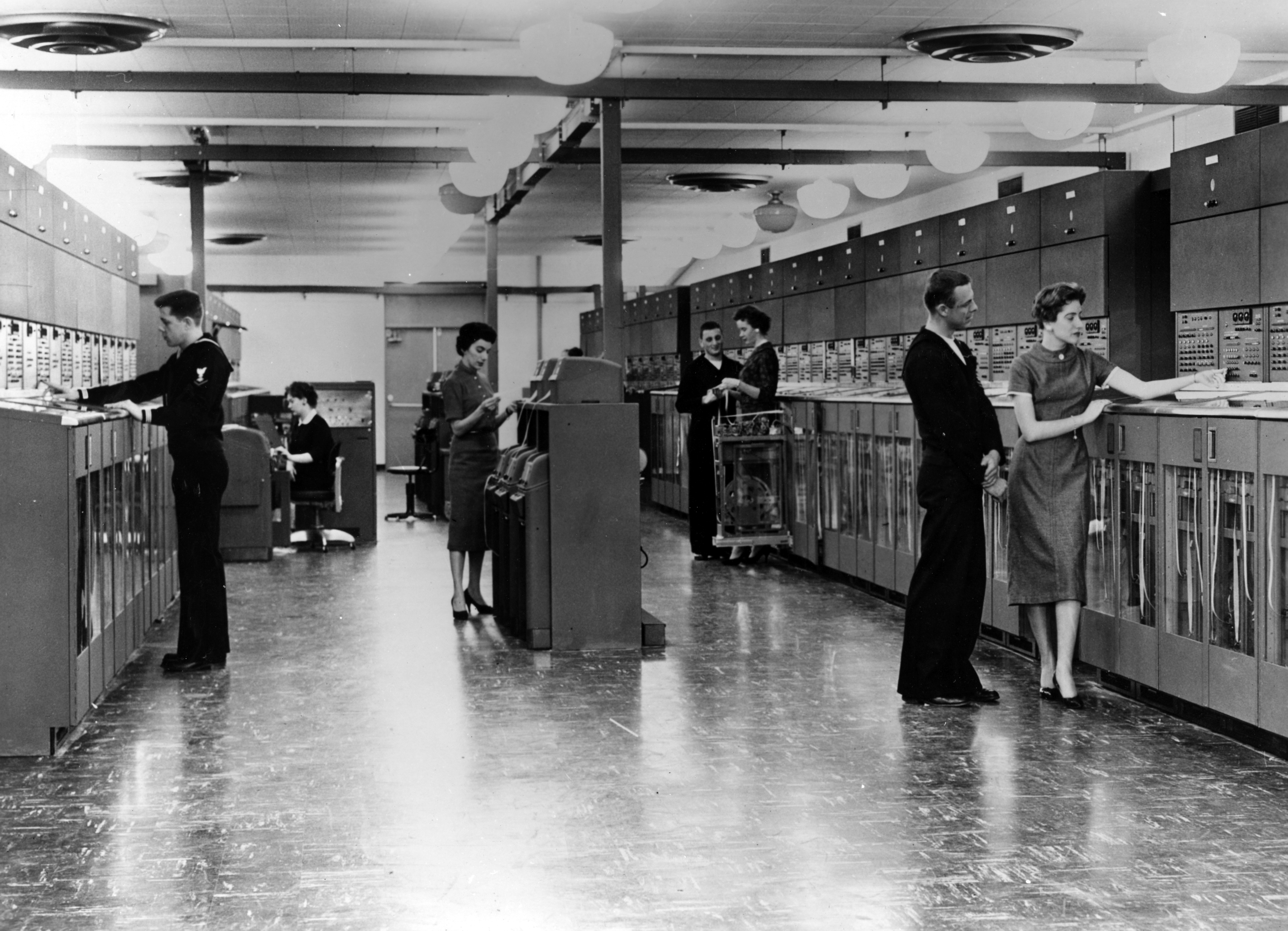
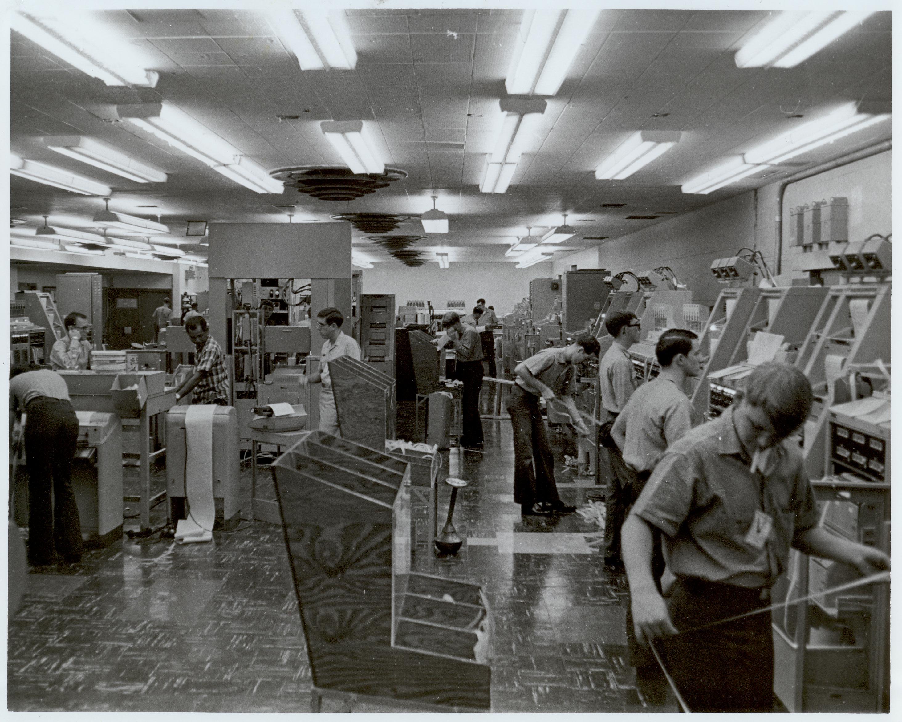
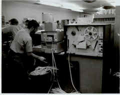
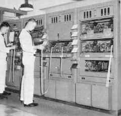
Torn Tape Relay System
Receiving Consoles on Right
Transmitting Consoles on Left

Operation of AN/FGC-38 tape
relay equipment shown above
|
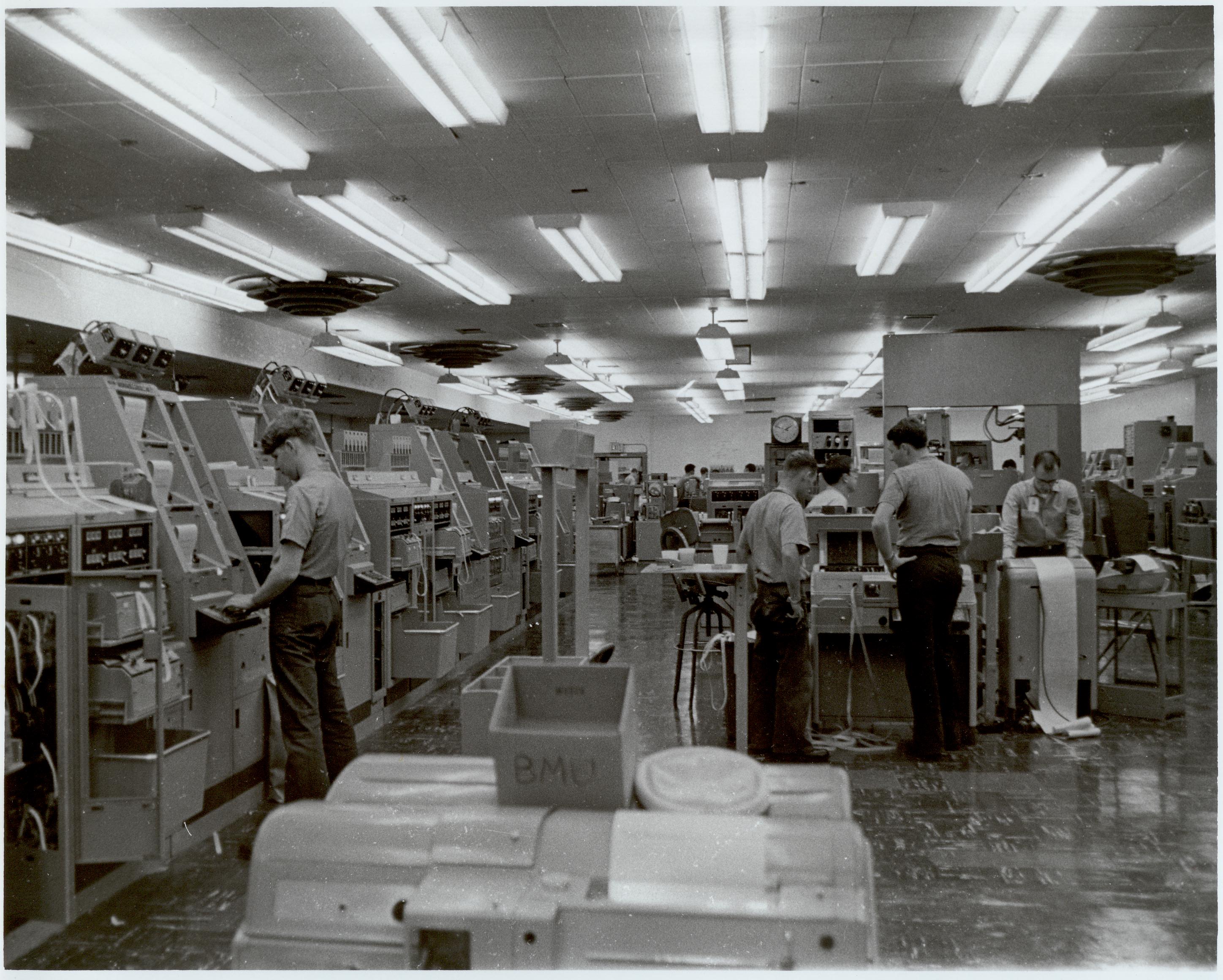
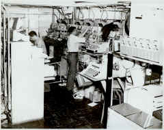
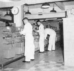
Torn Tape Relay
Receiving Consoles |
Figure 1 - Receiving Consoles
 |
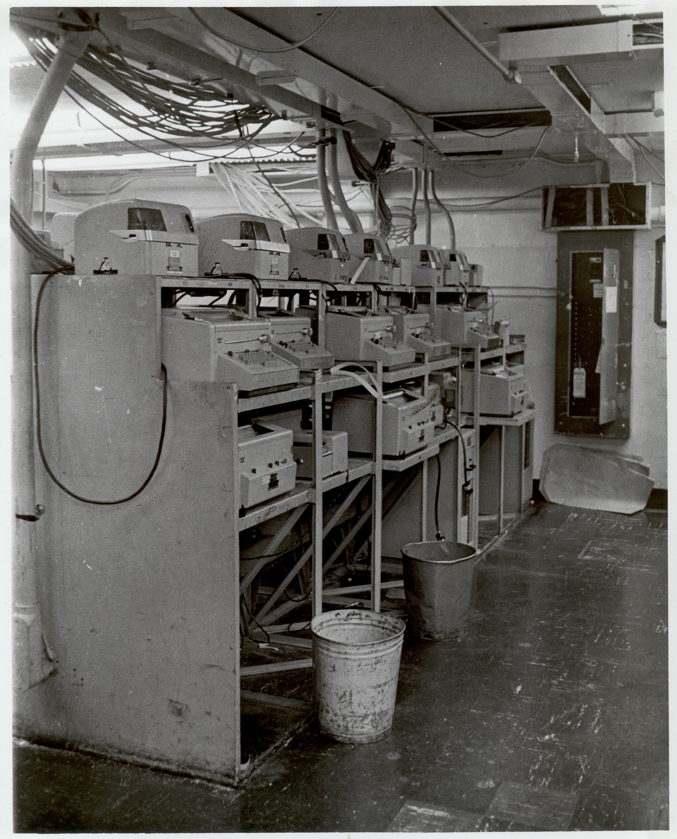
Receiving Reperforators

|
On board BB-62
 |
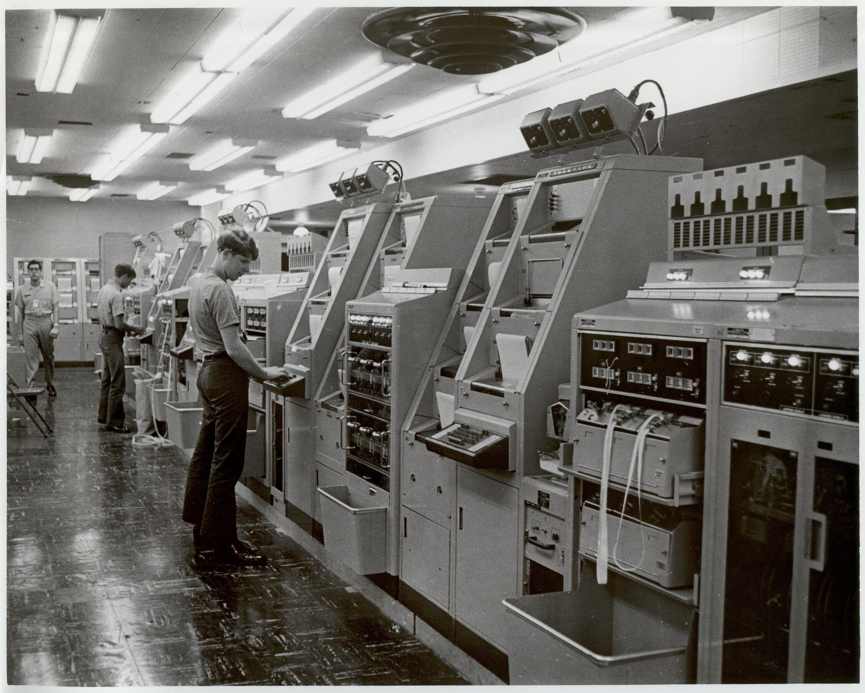
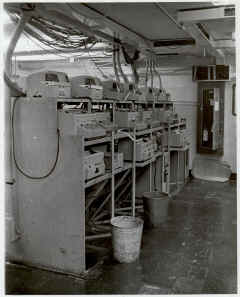
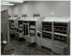
Torn Tape Relay
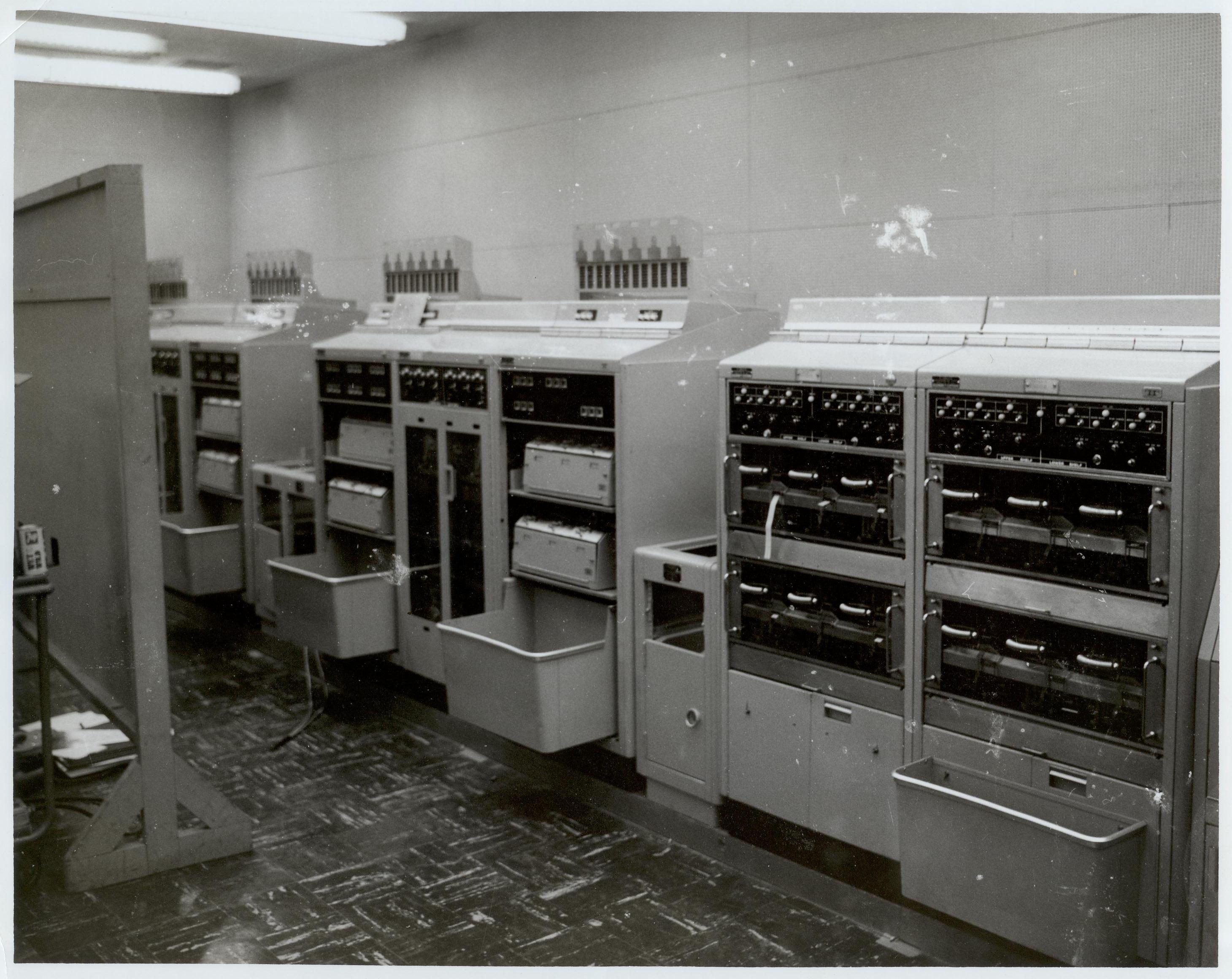
Transmitting Consoles |
Figure 2 - Transmitting Consoles
 |
Transmitting TDs
|
On board BB-62
 |
| -- |
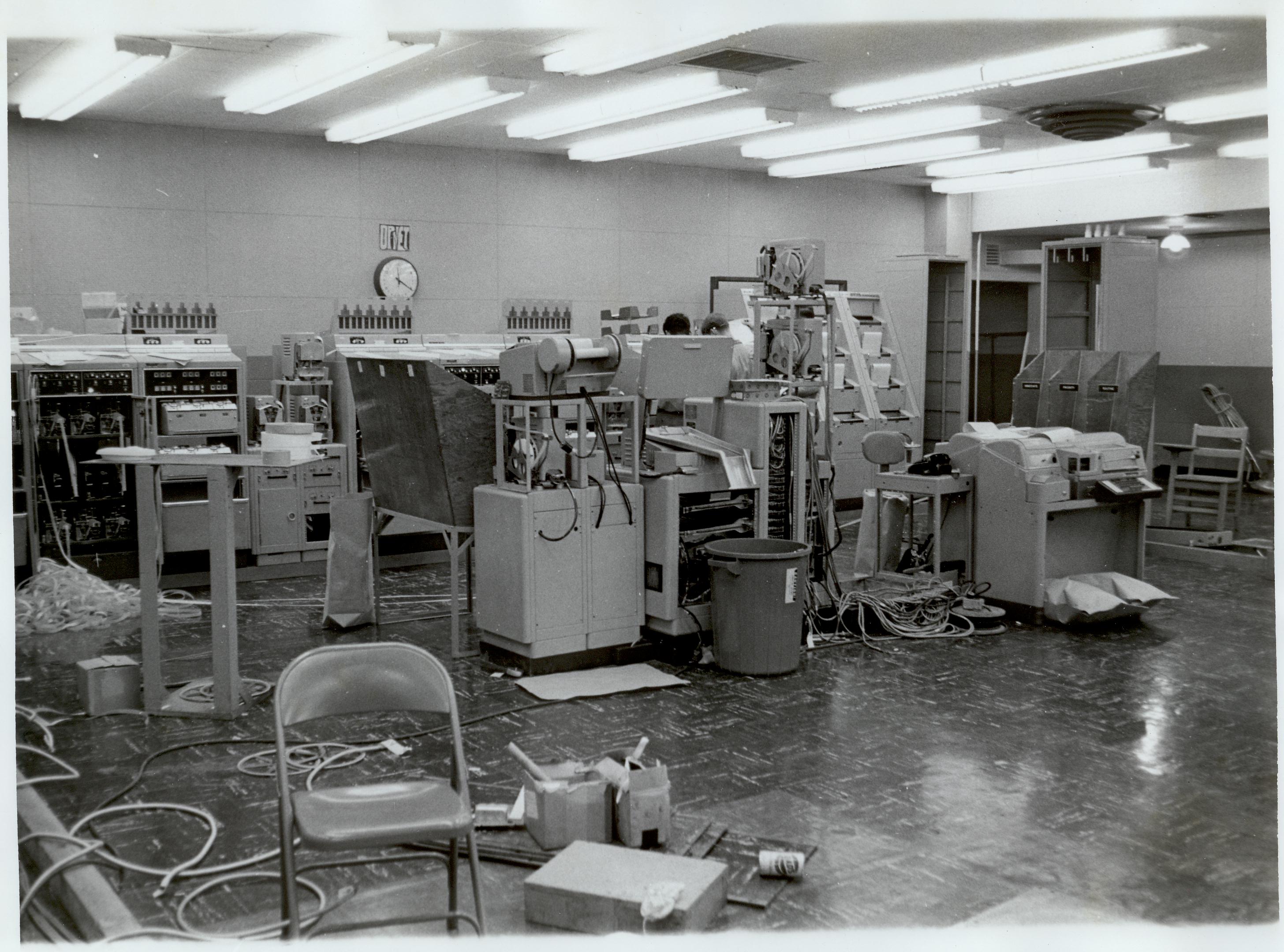
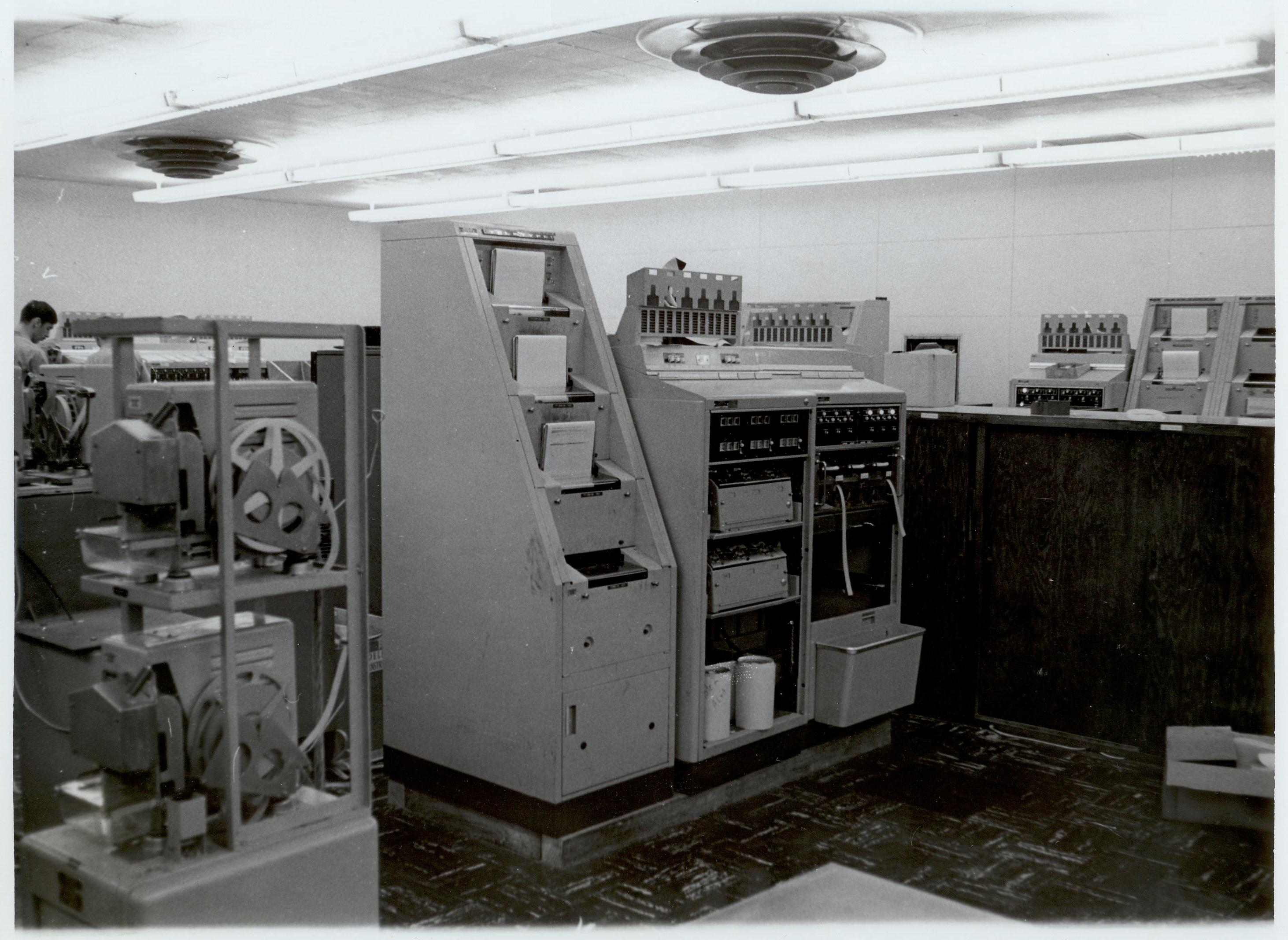
| FULLY AUTOMATIC RELAY EQUIPMENT (1962)
Video on Automatic Relay
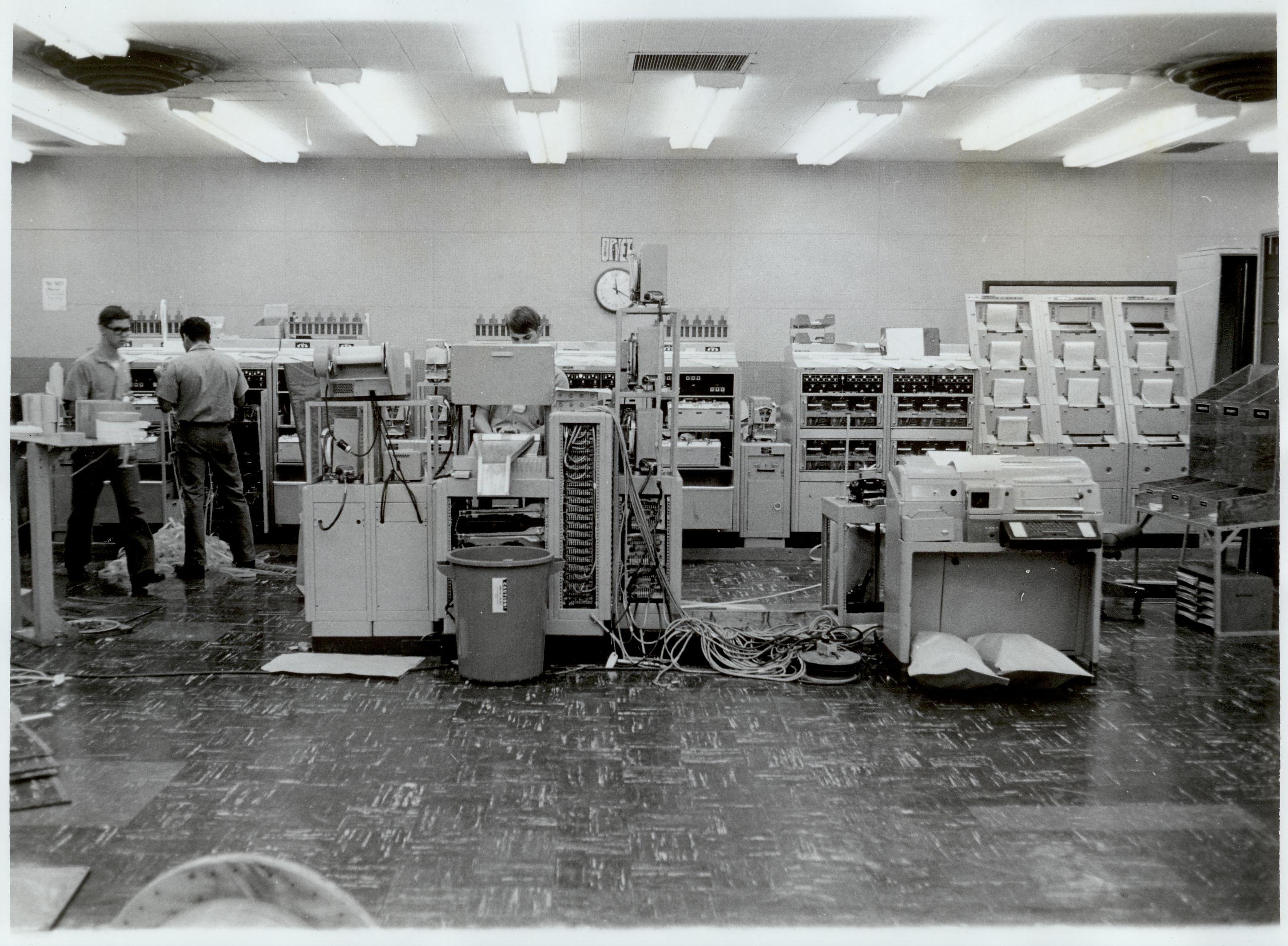
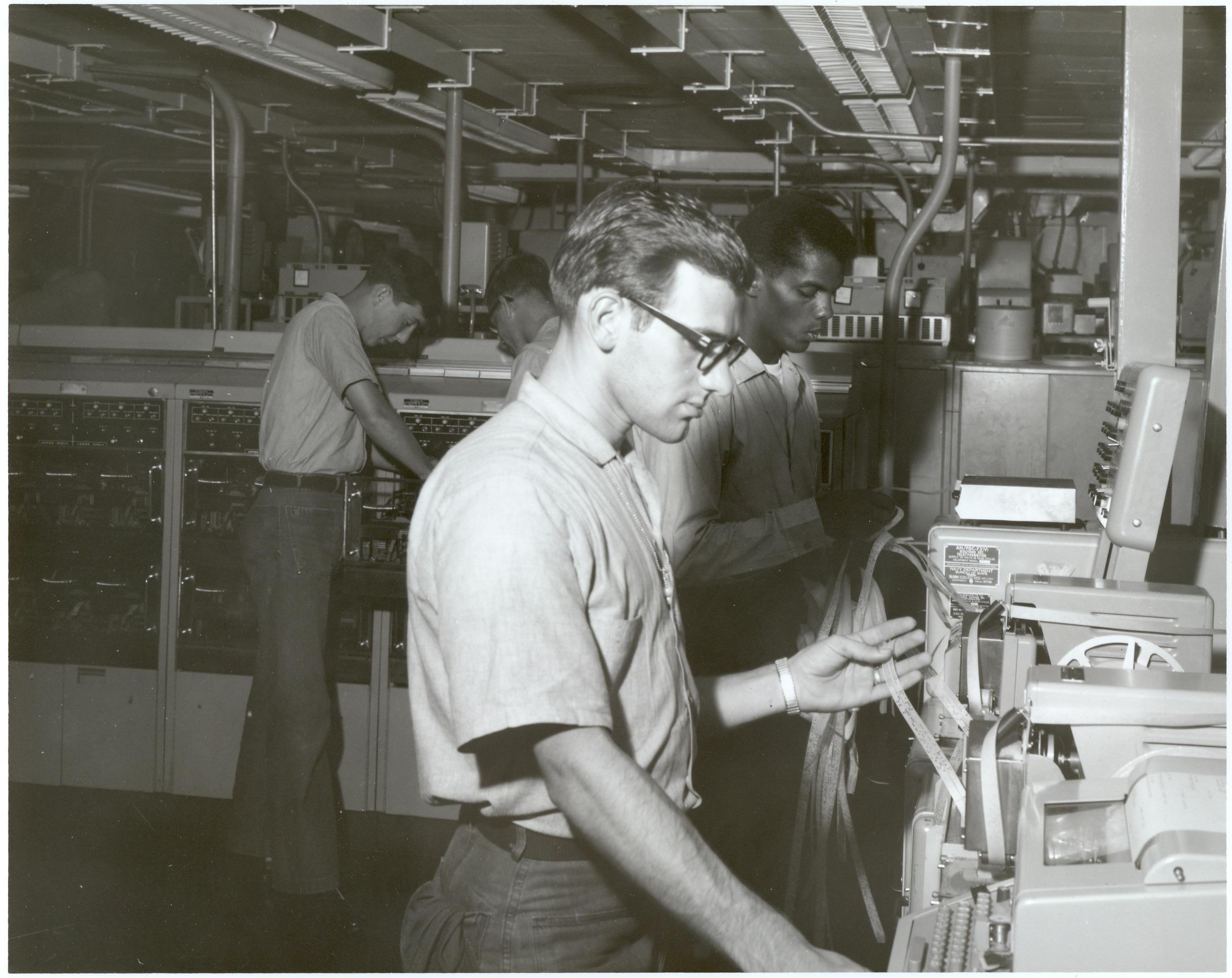
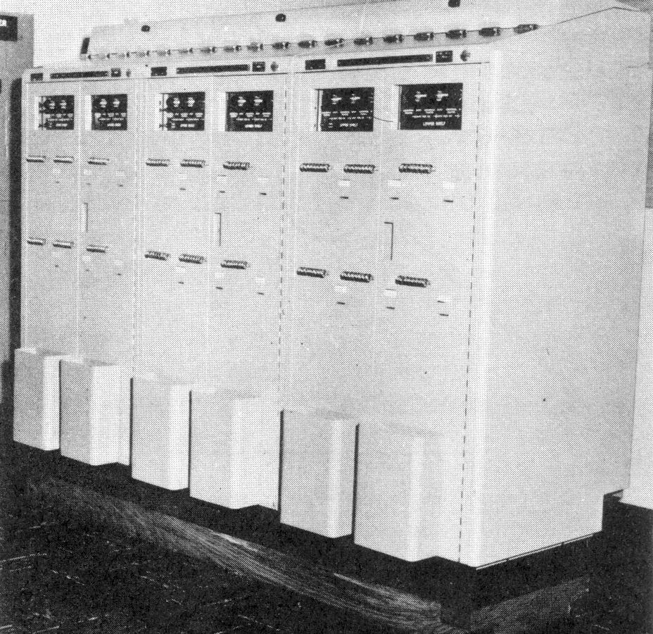
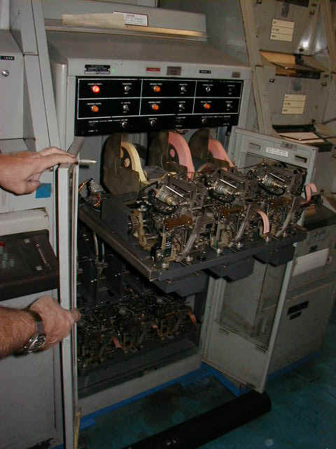
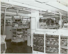
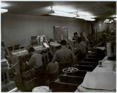
High-speed automatic relay centers are equipped with the very latest Model 28 teletypewriter components. The transmitter-distributors and reperforators are enclosed in cabinets which also contain the operating controls. Figure
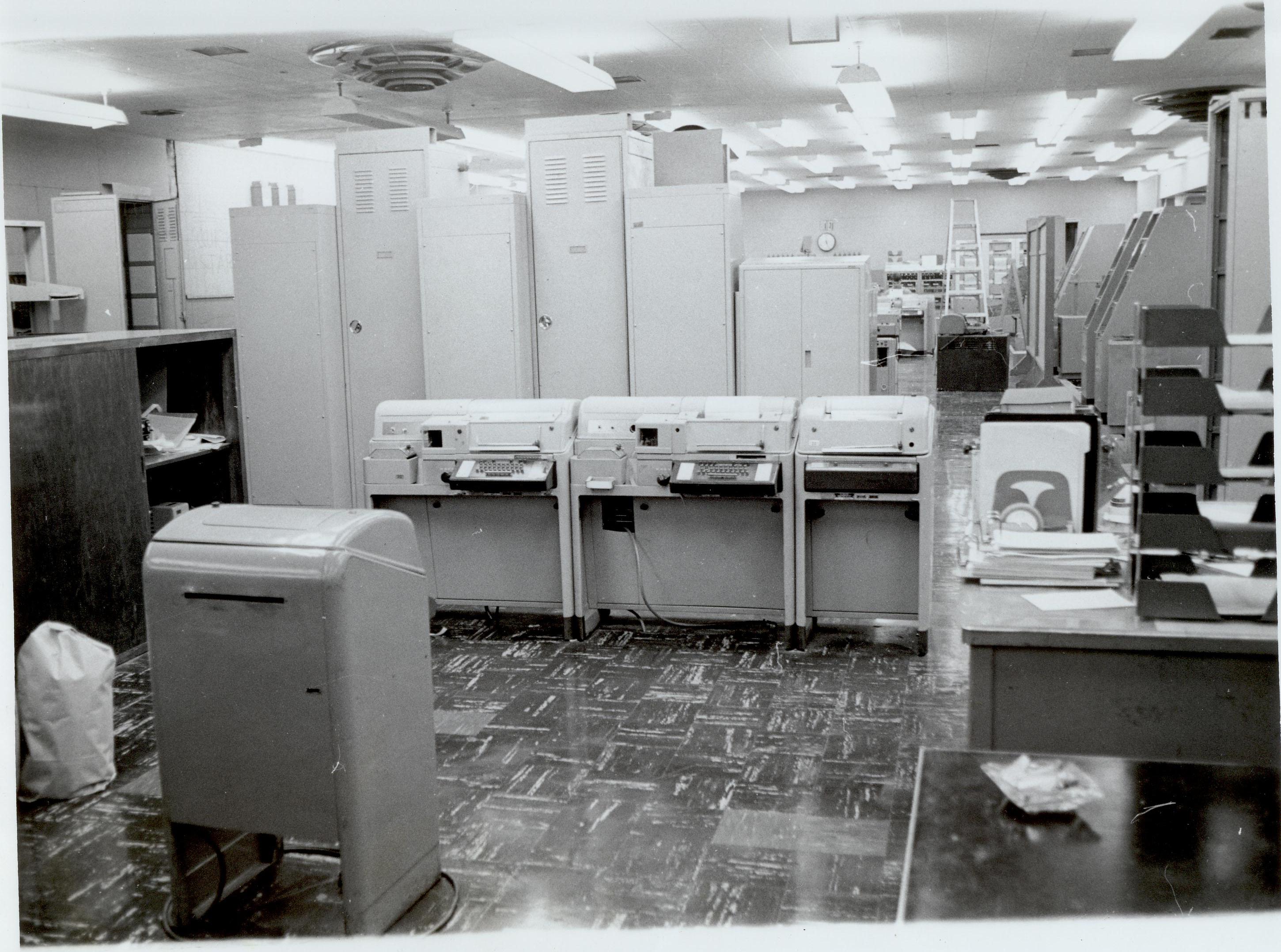
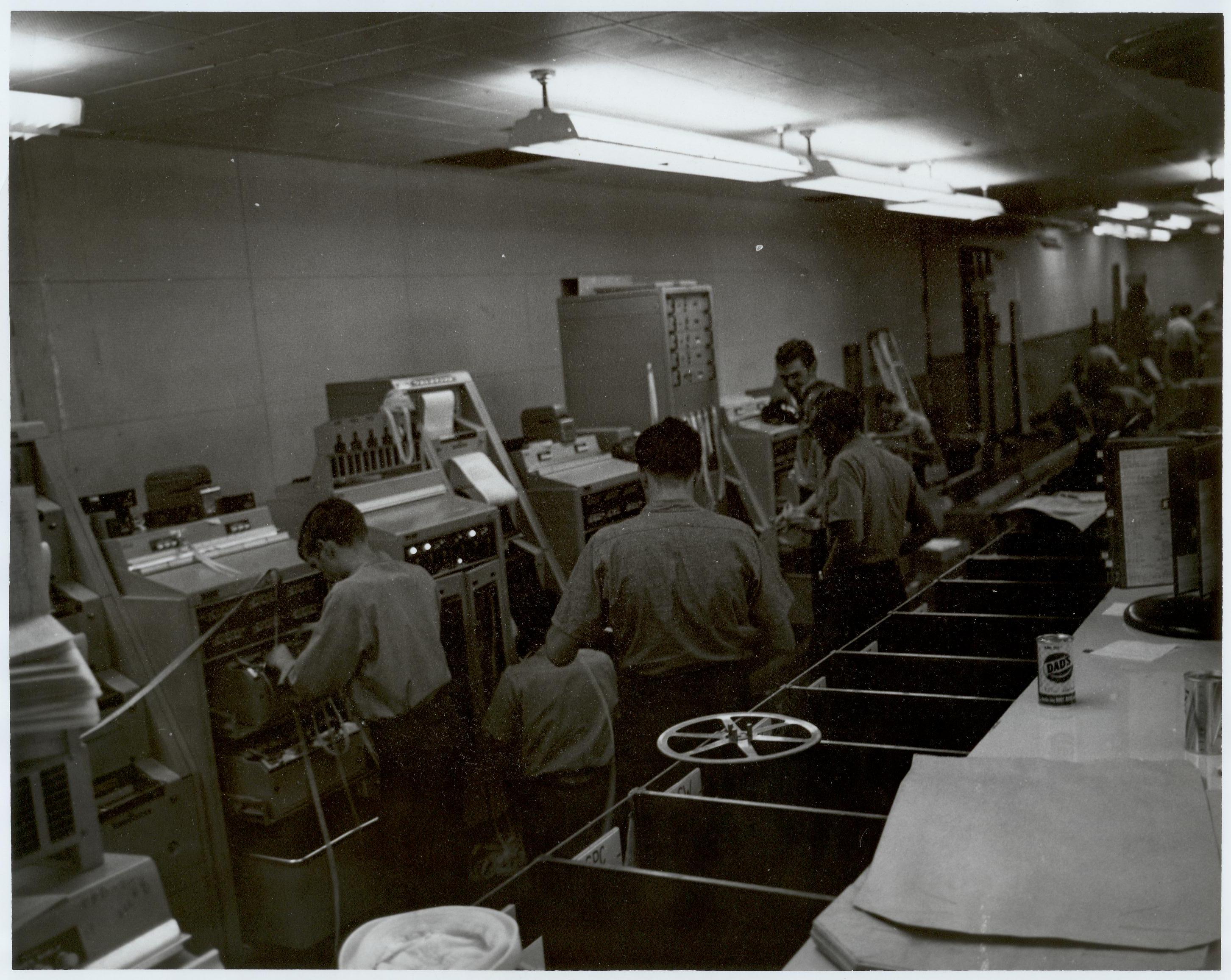
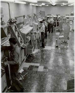
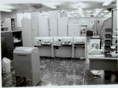
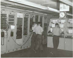
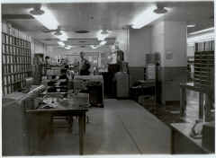
3 below shows the equipment layout at an automatic relay center. At left are the incoming line cabinets; outgoing line cabinets are at right. At center are the supervisor's control position and the miscellaneous intercept section.
There are two reperforator-transmitters in each incoming cabinet. They slide out of the cabinet for easy replacement in case of failure. The reperforator-transmitters operate at a cross-office speed of 200 WPM. Therefore, messages are relayed from the incoming line cabinets to the outgoing line cabinets in a matter of seconds. When necessary, a third machine can be assigned to an outgoing circuit, to which high precedence messages can be switched. The equipment is designed to "recognize" high precedence tapes; a message in this "priority" machine will cause its transmitter to take control of the line as soon as any message in progress has been transmitted. The transmitter will retain control until it has processed all urgent messages awaiting transmission. Only then will control revert to the two regular machines.
Traffic volumes to be delivered to a given destination may often exceed the capacity of one outgoing-line channel. In such an event as many as 10 machines and 10 line channels may be shifted to serve a single destination.
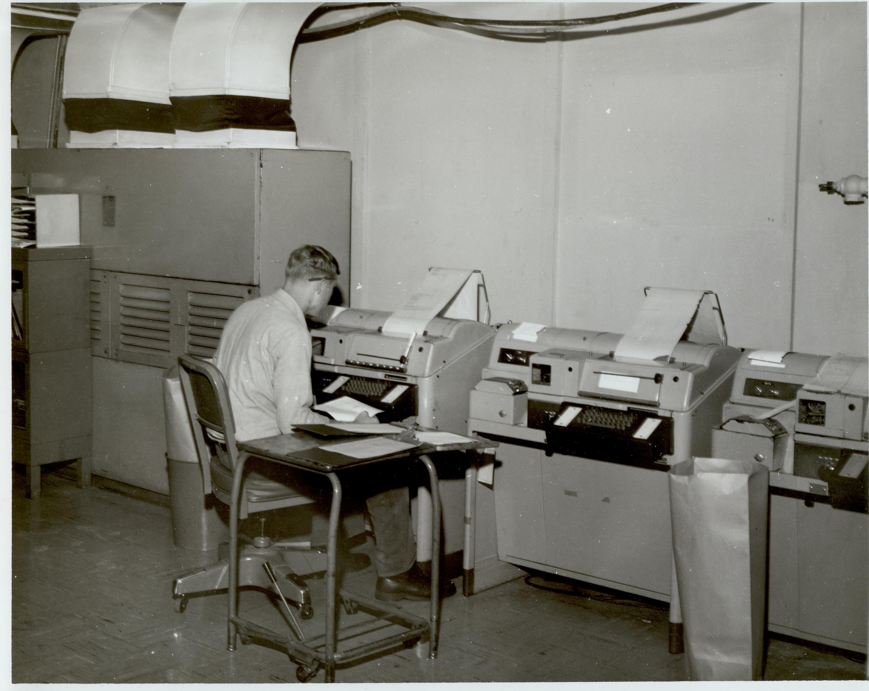
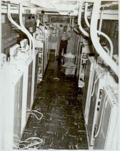
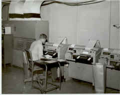
All lines are duplex circuits; that is, any station can transmit a message to the relay center at the same time that it is receiving a message. Each tributary station normally has two teletypewriters; one is a sending machine and the other a receiving-only teletypewriter. Automatic relay centers are manned by very few operators, compared with semi-automatic torn-tape relay stations. Improperly prepared or garbled message tapes are automatically routed to the intercept position
(fig. 4) for operator action. Correctly prepared messages enter and leave the relay center untouched by human operators.
To reduce the frequency of supplying the reperforators with fresh tape, the machines use a 3000-foot tape supply roll, instead of the usual 1000-foot roll used by Models 14 and 19 equipments. |
Figure 3 - Automatic Relay Center
(L) Receiving cabinets (reperf + TD)
(C) Intercept positions
(R) Transmitting cabinets (reperf + TD)
|
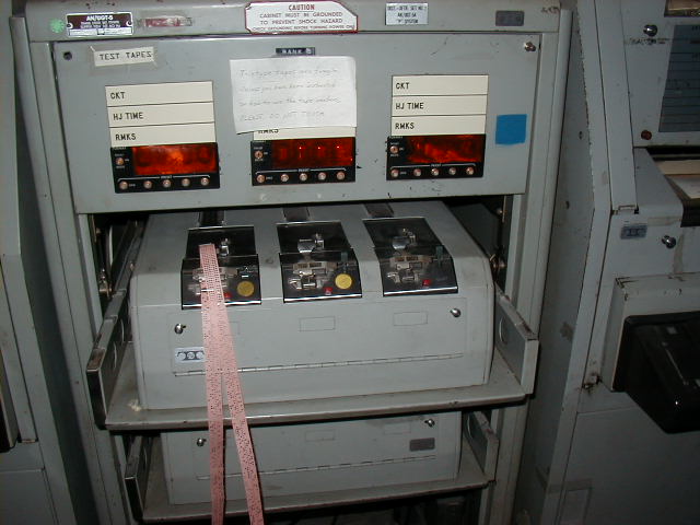
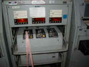
Figure 4 - Intercept positions in automatic relay center for garble
corrections, QC, etc.

|
82B1 system at Cheltenham 1959
|
82B1 system at Trenton 1950s
 |
| --- |
Message-Switching Centers
NAVSHIPS 0967-255-0010 - June 1967 - PRINCIPLES OF TELEGRAPHY (TELETYPEWRITER)
3.1 General
Large military communication centers, which require message-switching capabilities, use the store-and-forward technique. Message switching, involving store-and-forward methods, is a delayed type of switching. This method is opposed to circuit switching, which is a real-time operation, and is generally used in voice-switching telephone networks.
These message-switching centers, sometimes called tape-relay stations, require typing reperforators for recording incoming messages and transmitter-distributors for transmitting outgoing messages.
The principal classes of message-switching centers are manual (torn tape),
semi-automatic, and fully automatic centers.
Torn-tape centers require considerable manpower and can incur major traffic delays. Torn-tape working becomes difficult in a large center; hence, a variety of automated tape centers have been developed. The automatic tape centers introduced a major improvement in service and a reduction in manpower. A major feature is routing line segregation, which is the ability of the switching center to automatically separate the multiple address incoming messages and direct them to the correct outgoing lines. However, the automatic systems had serial storage problems and difficulties of access to priority messages back in the tape. In the large automatic centers, the tape machinery is subject to significant wear in this heavy-duty environment. Also, since the cross-office speed is only slightly in excess of line speed, queuing problems arise.
Recent developments use electronic storage to eliminate mechanical wear and improve grade of service. With its freedom of access, electronic storage is similar to the torn-tape office in that message-storage and cross-office handling is parallel, i.e., any tape may be drawn from
in-transit storage and dealt with, regardless of its chronological order of arrival. This gives great freedom for manipulation of precedence sequencing, etc. It also permits very high cross-office speed, thereby eliminating interval queuing and improving the minimum reaction time.
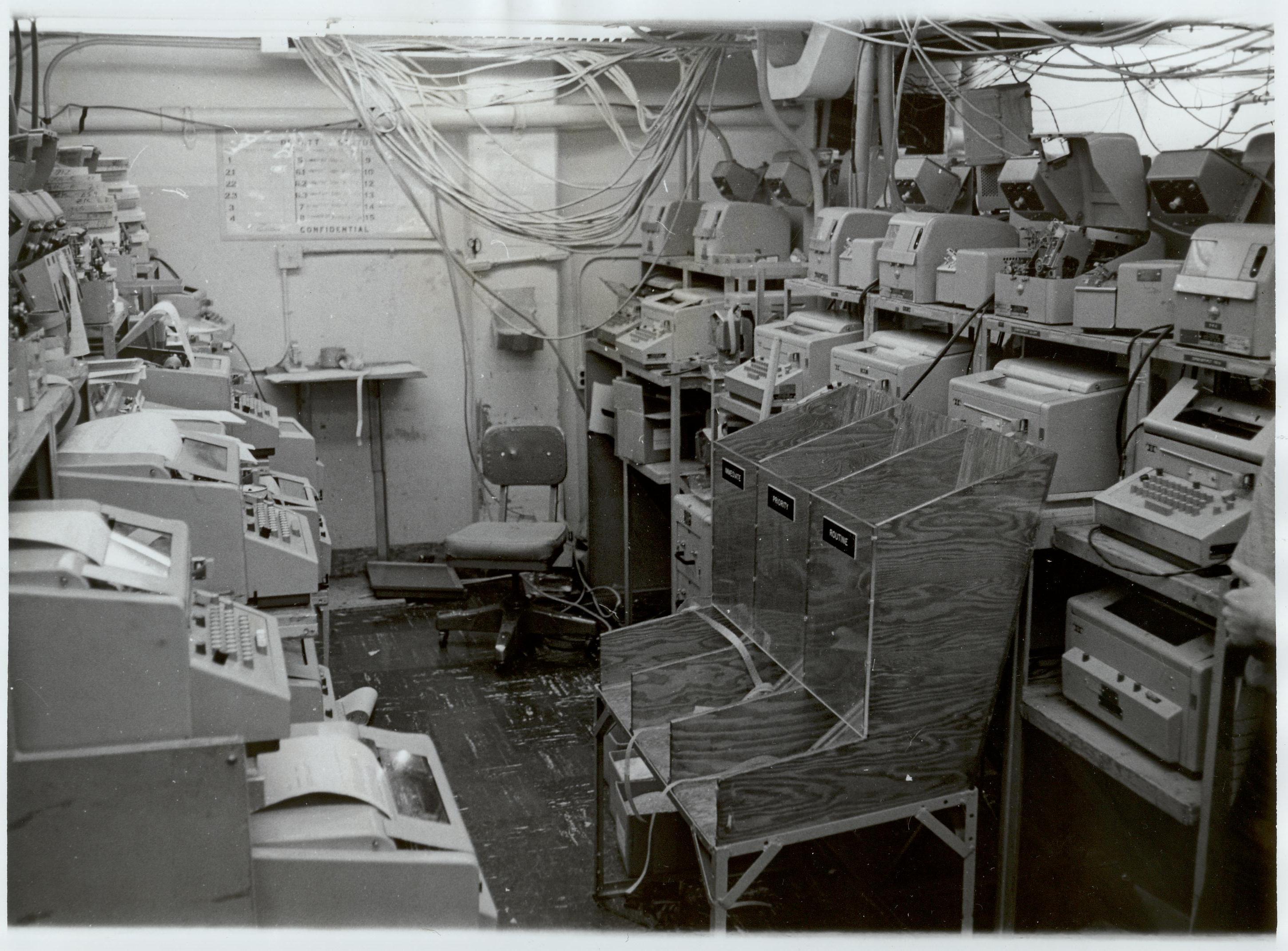
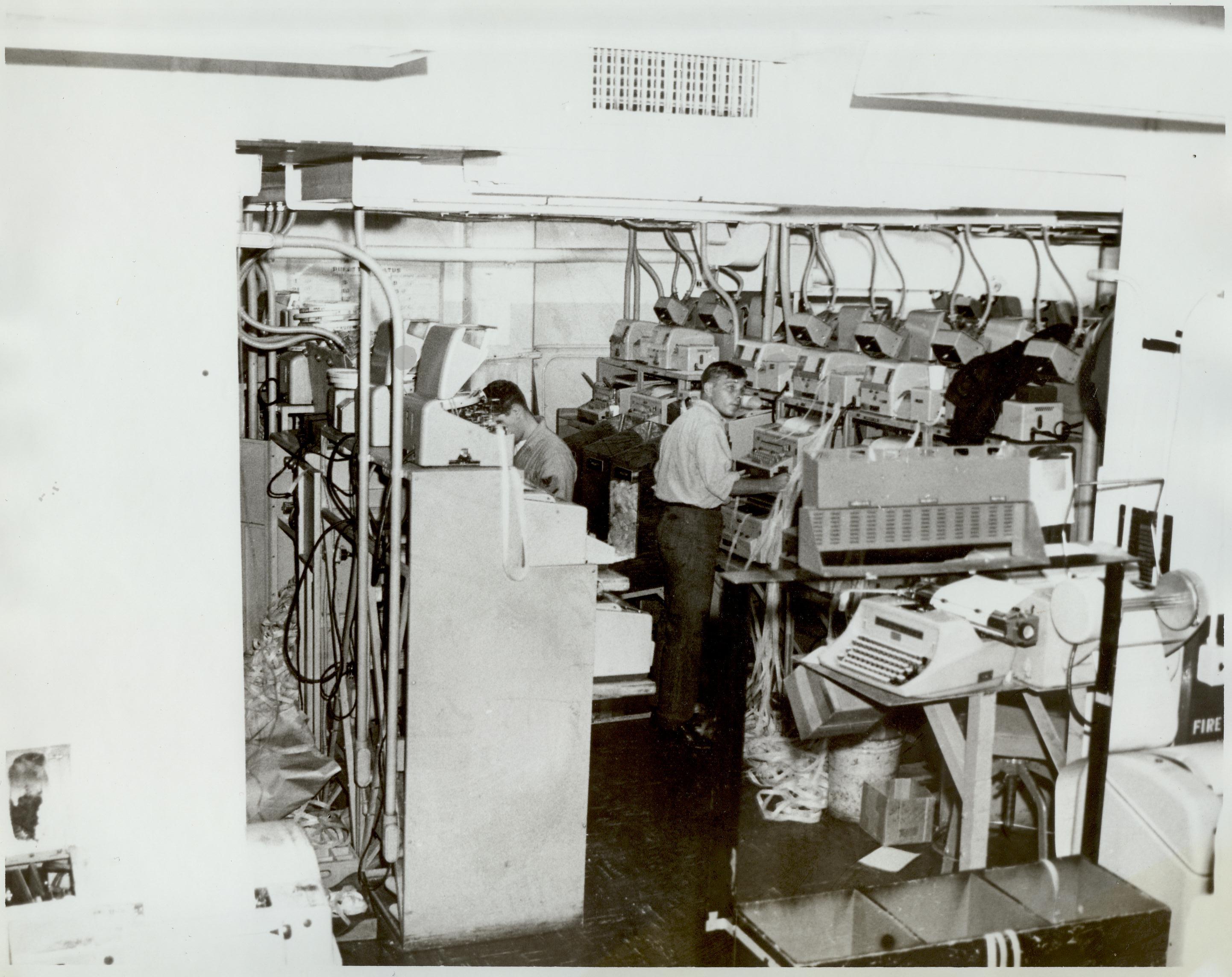
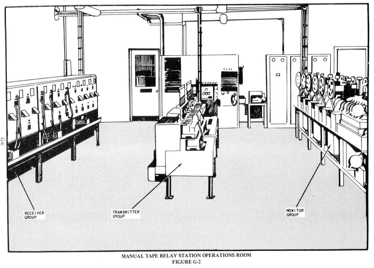
3.2 Manual Relay (Torn Tape)
The manual store-and-forward message relay (torn tape) center comprises a large percentage of the existing teletype relays in military communications. Single or multiple address messages in 5-unit International Number 2 Teleprinter Code are processed by these centers. The quantity of incoming and outgoing line units is readily increased by addition of standard modules of appropriate type. Each incoming
or outgoing line unit can be arranged to operate at one of three speeds (60, 75, or 100 wpm).
The speed change for message transmission is effected by the separation of these units.
In some switching centers, all messages are automatically duplicated, dated (in some cases, timed), and held in storage. In some cases, attendants correct errors in routing indicators or in the literal text before relaying onward. All tapes for relaying are temporarily stored, first within priority groups, and then on a first-come, first-served basis. When a message has preemptive ability, it is brought to the outgoing line immediately. At the discretion of the attendants, the preemptive message
interrupts the message being transmitted, or is sent immediately thereafter.
The manual center is divided into five basic units: incoming line unit (ILU), tape multiplication unit,
cross-office area, outgoing line unit (OLU), and intercept position. A monitor position may or may not be included.
The ILU is usually a typing reperforator that transforms electrical signals into punched paper tape form; a number of these machines are served by one operator.
No action can be taken on a message until it is completely received. At that time, the tape is torn from the ILU (hence the term torn tape), and carried to the
cross-office area. However, if the message has multiple routing indicators, it is forwarded to the tape multiplication unit instead.
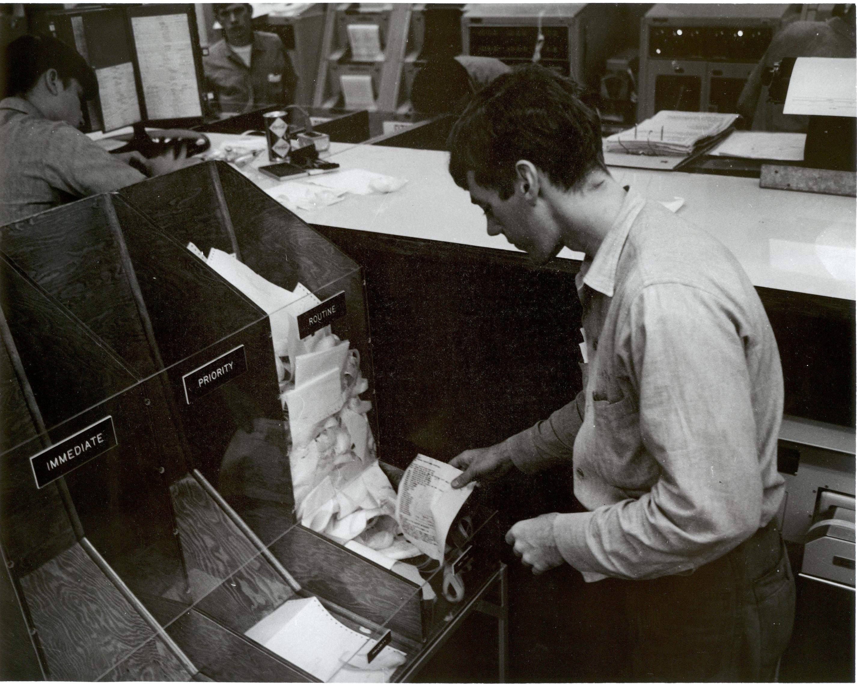
The cross-office area in a manual center consists of some type of storage from which the message can be transferred to the OLU. Such a device is often called a washboard. A tape is placed in a slot corresponding to its destination and within a particular precedence category. The tape is pulled by an operator on the outgoing side of the cross-office unit and inserted in the OLU. The tapes in the cross-office unit are served within priority groups on a first-come, first-served basis.
If the message has several routing indicators, the tape must be carried to a tape multiplication unit. This device is essentially one distributor transmitter and a number of reperforators in parallel. When the additional tapes are produced, each tape is placed in its corresponding destination slot on the cross-office unit. These are then treated as individual single address messages.
The OLU consists of distributor-transmitters, sometimes with page printers and often with typing reperforators for monitoring and message accounting. Where equipment is available, two transmitters may be connected to one outgoing line and operated alternately for improved efficiency.
Various errors will occur, e.g., invalid routing indicator, improper message format, or improper machine functions. Messages with errors are carried to the intercept position prior to any tape multiplication or
cross-office handling. Although relatively few messages contain errors, the delays resulting from the intercept operation are significant. Corrected messages from the intercept position are
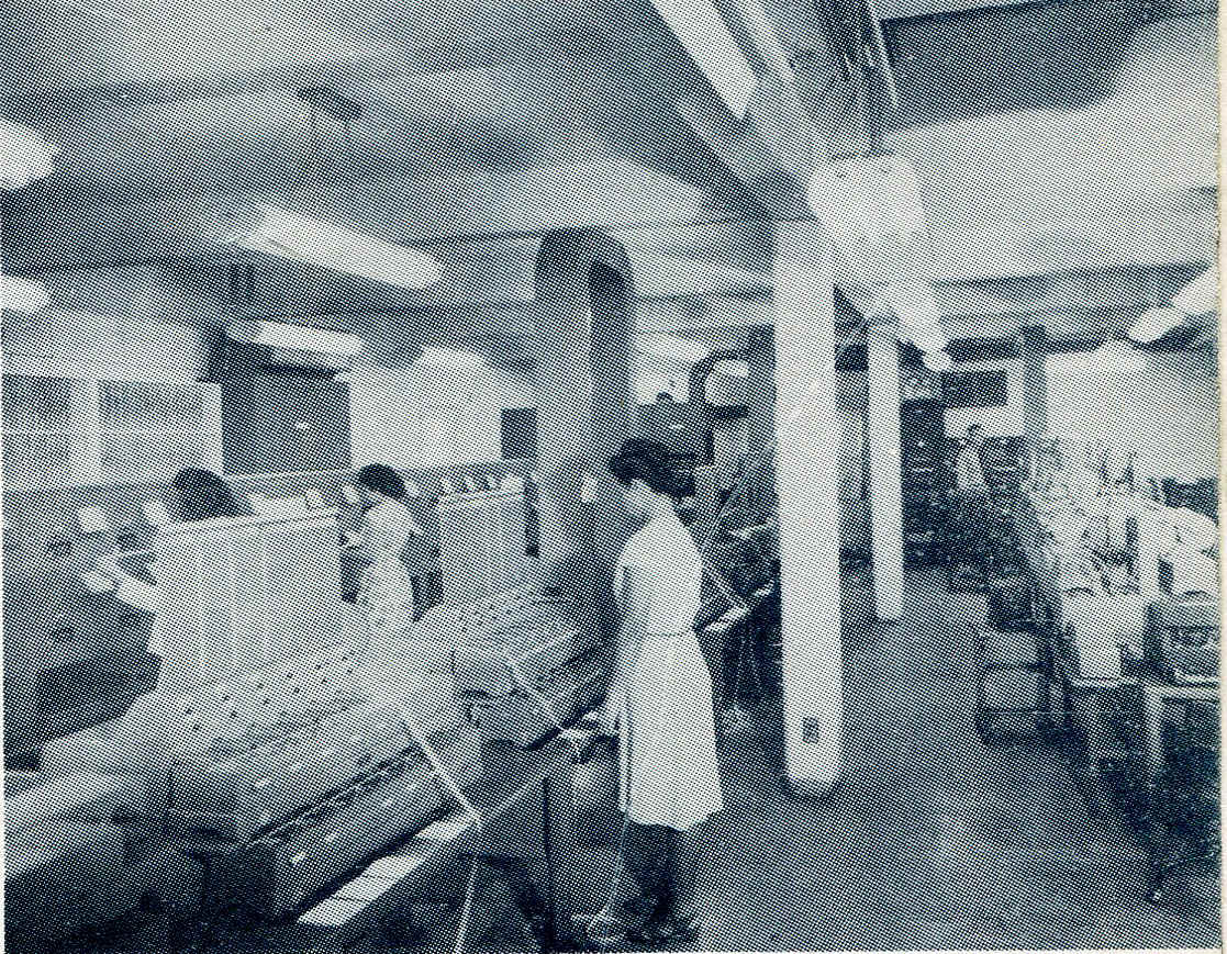
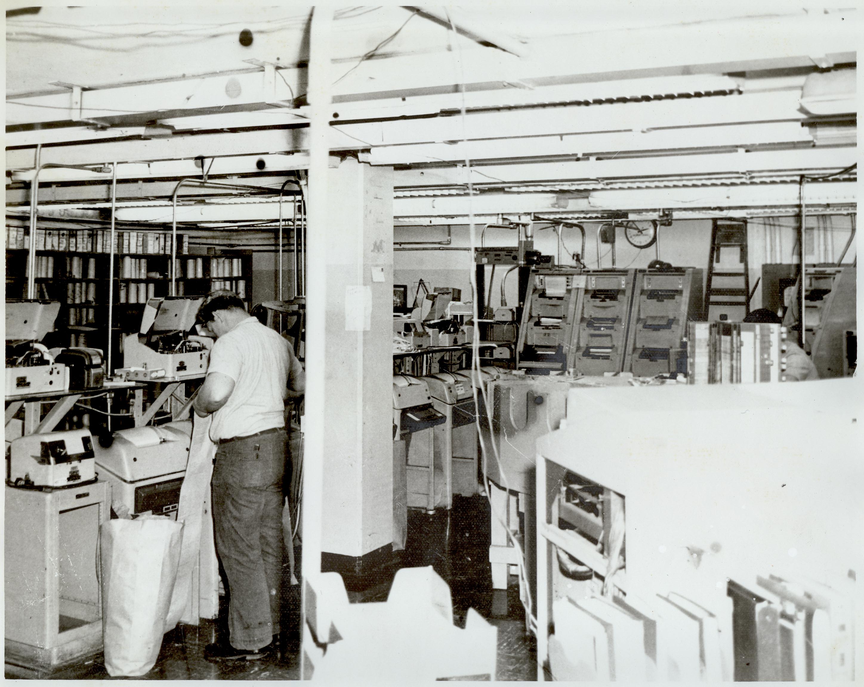
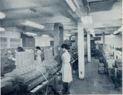
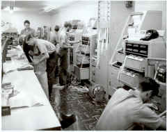
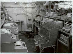
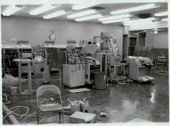
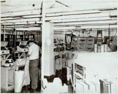
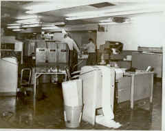
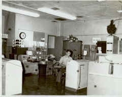
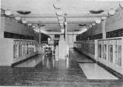
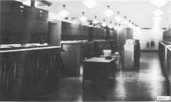
re-filed on a special ILU. From that point, the message is transferred cross office or the necessary additional tapes are prepared. Figures G-1 and G-2 show typical manual tape relay station operation rooms.
 |
 |
3.3 Semi-automatic Store-and-Forward Switching.
Limited use has been made of semi-automatic tape relay centers. This section describes the essential features of the military centers operating in this mode and utilizing Western Union Plan 51 equipment. The only other known
semi-automatic equipment is an electronic vacuum tube design operating in England which, although superior to Plan
51 , is not described herein.
In view of automatic electronic development, there appears to be little future for a
semi-automatic device. The Plan 51 is a semiautomatic message switching center, handling single and multiple address messages
in 5-unit International Number 2 Teleprinter code in ACP 127 format. This center consists primarily of
self-contained incoming units with pushbutton control for selecting the outgoing circuits. The proper connection through the center is established by the attendant, manually translating the routing indicator to an outgoing line designation. The start of message symbol and end of message symbol are automatically alarmed to alert the attendant. Routing indicators and channel designation serial numbers must be visually inspected for each incoming message. At this position the attendant will select the outgoing lines and transmit the message. If an error occurs in the routing indicator portion of the tape, the message is sent to an operator service position where the tape is corrected and reintroduced into the system. If there are errors in the literal text, these are corrected as well. An incoming message having a preemptive requirement is given preferential treatment, but no outgoing messages are cancelled in its favor.
Each incoming unit contains two typing reperforators with associated transmitter-distributors for serving two incoming lines. The pushbutton selector panel with associated alarm circuitry requires an attendant to perform each function. The channel designation serial number is visually inspected and the proper outgoing line is selected after translating the routing indicators. The message is transmitted cross-office at 75 wpm to another reperforator and transmitter-distributor, which is associated with the line. If the message has multiple routing indicators, it is routed to the master sending position, which may select more than one cross-office line. Incoming and outgoing message speed is 60 wpm.
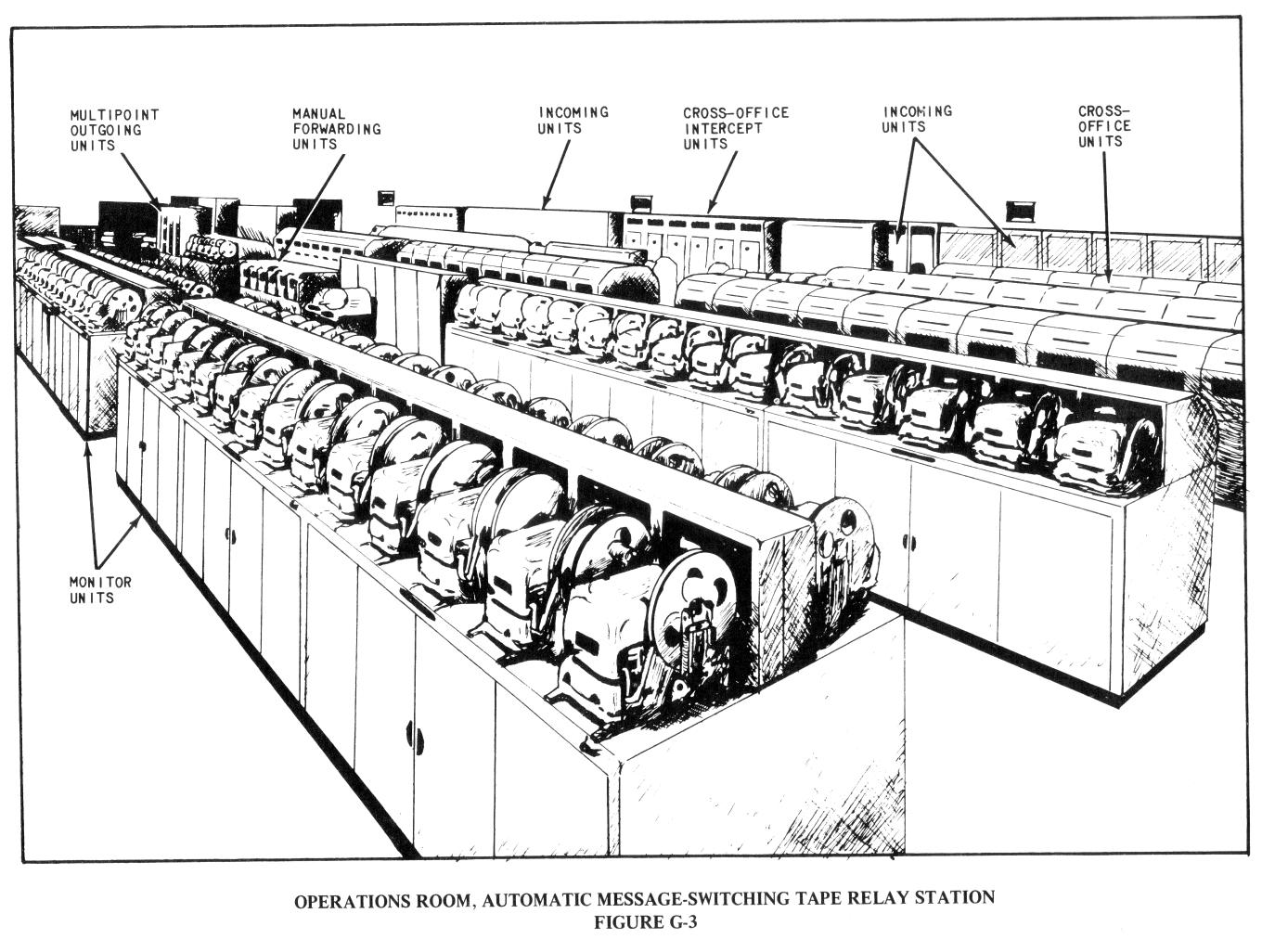
3.4 Automatic Store-and-Forward Switching
A number of automatic tape relay centers have been developed. The characteristics of the three main military systems are outlined in this section. The AN/FGC-30A is a message-switching system used by the U.S. Army for its common user teletype network. The 82-B-1 is a system used by the Navy for its common user teletype network connecting the automatic relay centers. The Plan 55 is automatic message-switching equipment used by the U.S. Air Force in a network of key Air Force centers located in various
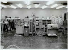
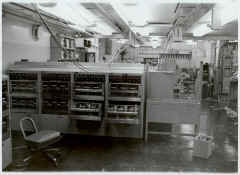
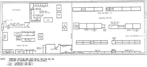
parts of the world. Other forms are in use but the trend is to supersede these tape centers by electronic centers. Figure G-3 shows an operations room, automatic message-switching tape relay station.

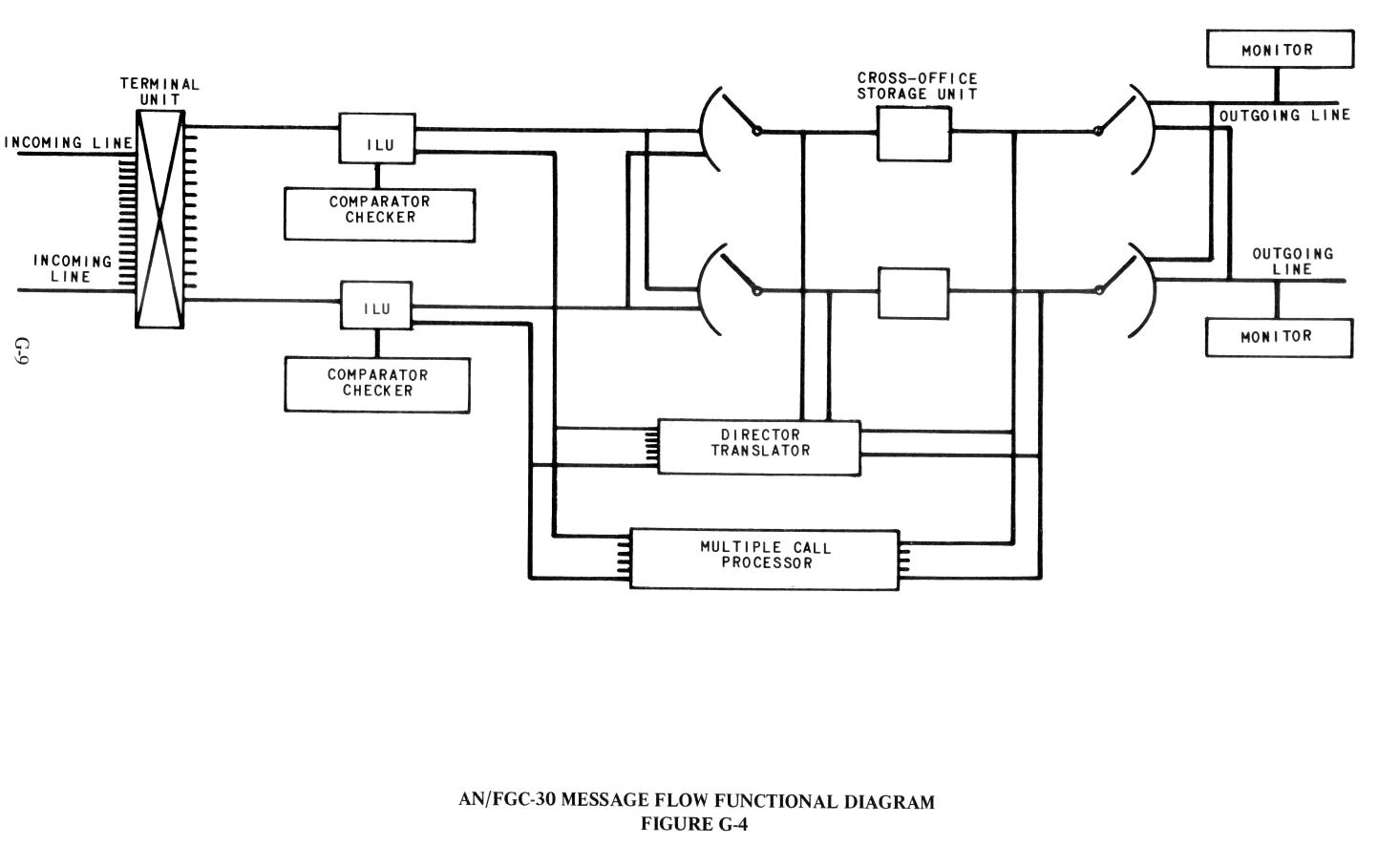
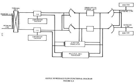
3.4.1 Automatic Relay Center (AN/FGC-30A).
The AN/FGC-30A is designed to operate as a fully automatic message-switching center (Figure G-4); under emergency conditions, it can continue to function as a manual (torn-tape) center. Single and multiple address messages in the 5-unit International Number 2 Teleprinter code in ACP 127 format (Communication Instructions Tape Relay Procedures) are received by the center at speeds of either 60 or 100 wpm. All incoming channels are connected to an incoming line unit (ILU) where circuit access jacks allow monitoring and patching when required. The number of incoming line units, each serving two lines, is readily changed by the addition or removal of standard modules. A group of 13 ILU's (25 incoming lines plus 1 spare position, all operating at the same speed) is served by one director. The cross-office area consists of a common control with associated directors, translators, cross-office storage units, and
reperforator-transmitters. When both channel speeds are used, two pools of cross-office storage units, each served by a director, are provided. These serve as temporary storage areas where tapes are grouped by precedence and outgoing line. Any cross-office storage unit can be accessed by any ILU, since there is no outgoing line unit (OLU) as such. The reader-transmitter of the cross-office storage unit transmits directly to the line and to a monitor reperforator for that line.
If an error occurs in the heading, the message automatically bypasses the cross-office unit and is sent to an intercept position.
Here the errors are corrected, including any in the literal text.
When a message has a preemptive requirement, it is transmitted to an idle cross-office storage unit. A lower precedence message being transmitted to the required outgoing line is canceled, regardless of the time to completion, and the outgoing line is seized for the higher precedence message. The lower precedence message is repositioned in the cross-office storage unit by the attendant, and is then retransmitted in its entirety immediately following the preempting message. Routing line segregation is always employed in this center.
The incoming lines terminate on an intermediate distribution frame (IDF). Plugs and jacks facilitate connection of any line to any ILU. Each ILU consists of two reperforator-transmitters with associated channel designation serial number checkers. The transmitter sends the precedence and routing information as electrical signals to the director. If the message has a single routing indicator, it is then forwarded by the director to an individual cross-office storage unit; multiple address messages are processed by the multiple address unit before routing to various cross-office storage units. A director operating at 75 wpm serves all 60-wpm incoming lines; the 100-wpm lines are served by another director operating at 115 wpm. As much as 100 feet of perforated tape can be held in the incoming reperforator before being transmitted cross office. As messages are transmitted cross office, the tape is then placed on reels to maintain a permanent record of incoming traffic.
The director decides which cross-office unit will accept the message from a particular incoming line. After the outgoing line has been identified, and the
cross-office unit has been selected, the director is released to serve another incoming line. The message, reperforated at the cross-office unit, is filed behind others of equal precedence in the unit, and these are then processed on a first-come, first-served basis. A preemptive message is directed to an idle cross-office unit. The message on the required outgoing line is canceled, the cross-office unit seizes the line, and the priority message is immediately transmitted.
When the director detects a multiple address message, control is turned over to the multiple address unit (MAU). This equipment acts as a director, and stores the precedence and the first routing indicator of the message. After identification of the outgoing line, the proper cross-office unit is seized, and the heading and routing indicator is read from the tape, a second
cross-office unit is seized, and the heading and routing indicator are transmitted to it. All the cross-office units required by the routing indicators are seized and held. (A seized unit may receive several routing indicators. building up new multiple address messages for breakdown at further relay centers.) When all routing indicators have been transmitted, a multiple transmission of the remaining message is sent to all the held units. From this point on, transmission from each unit to its outgoing line is accomplished independently. Each MAU has a page printer that monitors all transactions, printing only sufficient characters of the heading for the operator to check the routing.
Each outgoing channel has an associated monitor typing reperforator. The reader-transmitter in the
cross-office unit sends directly out to the line. Tapes in the cross-office unit and in the monitor unit are reeled to provide a permanent record.
Incoming messages with heading errors are automatically sent to the intercept position where the messages are reperforated. An attendant corrects the heading when possible or requests a repeat transmission. The corrected heading, followed by the message text, is inserted into a manual forwarding unit. This unit is electrically identical to a cross-office storage unit, and line
seizure is on the same basis. Transmission of the message to the line is automatic. Normally, if errors occur in the text, these are also corrected here.
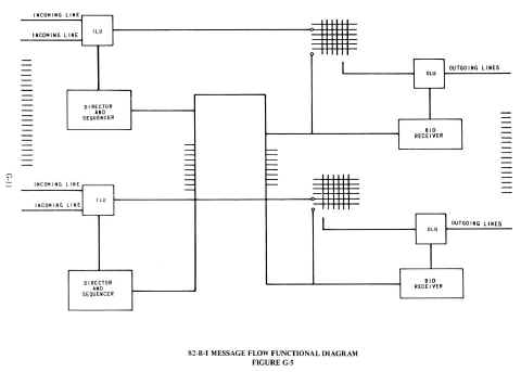
3.4.2 Automatic Relay Center (82-B-1). - Navy 82B1 Switching Centers - diagrams &
photos
The 82-B-1 is a fully automatic message-switching center (Figure G-5). Single- and multiple-address messages in the 5-unit International Number 2 Teleprinter Code in ACP 127 format are handled. This center consists primarily of self-contained ILU's and OLU's, which function as a complete switching center with no supplementary
cross-office equipments. Each incoming or outgoing line can be arranged to operate at 60, 75, or 100 wpm.
The ILU director is the key element in this switching center. It reads, analyzes, and stores all routing indicators, and selects the proper outgoing line for each addressee. When the outgoing line is identified, the director sends a request to transmit to the selected unit.
Cross-office transmission does not start until the outgoing line typing reperforator is free. A message being sent to one or more outgoing lines automatically brings about routing line segregation. An error in the heading sends the message to the intercept position for correction, after which it is reintroduced into the system. A preemptive message is given preferential treatment, but no outgoing messages are canceled in its favor.
Each ILU contains three
reperforator-transmitters, two for incoming lines, the other for the director circuit. These units copy the message and send the information cross office to the OLU. The director circuit reads and stores the routing indicators and precedence and indicates that the cross-office path is established wherein the message is automatically transmitted to the OLU and the director disconnects. If the request to transmit is denied, the ILU waits until the outgoing line is free. Storage for 12,000 characters is provided at each ILU.
When the ILU director detects a multiple-address message, it translates all the routing indicators, etc., but does not transmit until all the outgoing lines are available. A monitor records a tape copy of each outgoing message.
Each OLU serves four outgoing lines with associated reperforator-transmitter units controlled by two bid receiver circuits. Each OLU also contains two crossbar switches, which perform all cross-office connections. Each outgoing crossbar switch is capable of connecting to any ILU.
Incoming messages with heading errors are automatically sent to the intercept position where they are corrected and then reinserted into the system through a local send station.
Video on 82B1
Automatic Relay
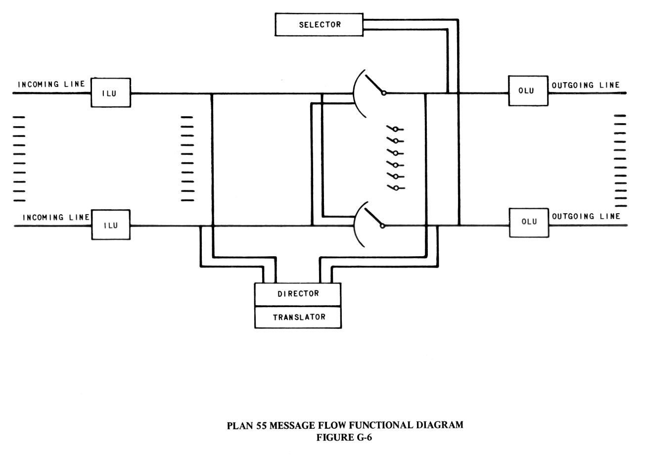
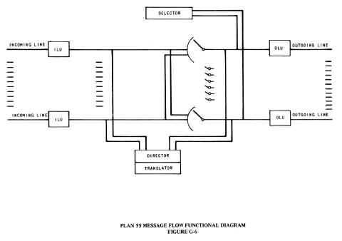
3.4.3 Automatic Relay Center (Plan 55). - Western
Union Plan 55 document - Western
Union film including scenes of Plan 55 switching centers
The Plan 55 operates as a fully automatic message-switching center (Figure G-6) or as a semiautomatic (pushbutton) center if the cross-office routing director and translator are
omitted. Single- and multiple-address messages in the 5-unit International Number 2 Teleprinter Code in ACP 127 format are handled. ILU's and OLU's, each serving two lines, can be independently arranged to operate at either 60 or 100 wpm. Each group of 13 ILU's (25 incoming lines plus one spare position) is served by one director. All incoming lines served by one director may operate at either 60 or 100 wpm. The cross-office area consists of a bank of rotary switches with associated director-translator and manual incoming-outgoing line selector. Precedence and routing indicators are transmitted to the director-translator where they are translated to identify the outgoing lines. The message is transmitted cross office at 200 wpm, directly to the reperforator in the OLU if it is idle; otherwise, the message waits. Sending the message to more than one outgoing line automatically brings about routing line segregation. The OLU affords temporary storage for all messages for that line. An error in the heading alerts
the attendant, and the message is carried to the intercept position where the tape is corrected and reintroduced into the system. An incoming message having a preemptive requirement is given preferential treatment, by manual intervention.
Each ILU consists of two typing reperforators, two loop-gate transmitters with associated control, and alarm circuitry. The typing reperforators copy the message, and the loop-gate transmitter sends the information cross office to the OLU. The first sender of the loopgate transmitter sends the routing information to the director-translator. If the typing reperforator in the selected OLU is free, the message is immediately transmitted by the second sender and the director disconnects. If there are more than four routing indicators,
a multiple-address overflow unit at the intercept position and three outgoing lines receive the message. The first sender sends to the director-translator at 200 wpm; in this way, the incoming line speed is independent of the director. Each incoming line has storage capacity for 120,000 characters.
There is no message storage in the cross-office area. Equipment includes boards for connection indicators, traffic routing, and closeout indicators, and reperforator transmitter sets for error correction. The traffic routing board is used for making temporary changes in the routing of messages by the use of patch cords and a jack field. If the director-translator is out of service, pushbuttons on the connection-indicator board can be used to set up the cross-office switches between the ILU's and the OLU's.
A multiple-address message is not transmitted cross office until all routing indicators have been processed, and all outgoing lines have been identified. Routing indicators per message are limited to nine. An incoming sender cannot access more than four outgoing lines at one time. All preliminary operations for a
multiple address message with up to four indicators are the same as for a single-address message. Messages to more than four outlets are transmitted to three OLU's and the multiple tape intercept position, from which point one message is reintroduced into the system and recycled.
Each OLU serves two lines, with typing reperforators and transmitter-distributor senders operating at either 60 or 100 wpm. Each OLU has storage capacity for 120,000 characters and can access any ILU. When a message with a preemptive requirement arrives at the OLU behind an accumulation of messages, an attendant manually places the preemptive message at the head of the queue.
Incoming messages, which cannot be automatically routed or processed because of a heading error, alert
an attendant who corrects the error and then inserts the corrected message in the transmitter of the local send station.
3.5 Electronic Switching Center (AUTODIN) - [AUTODIN page]
3.5.1 General.
The Defense Communications Agency (DCA) is presently building a worldwide Automatic Digital Network (AUTODIN), which will permit maximum use of circuits and improved speed-of-service.
The network comprises message and circuit switches, which will accept and relay traffic between card punch terminals, magnetic tape terminals, digital computers, teletypewriters, paper tape readers and punches, digital graphic transmitters and receivers, and digital voice subscribers. A subscriber equipped with any of the message terminal devices may communicate with other subscribers equipped with different message devices.
The Continental United States (CONUS) AUTODIN switching system is being augmented by modification of five presently installed switches and the addition of four similar switches. To satisfy digital requirements on a worldwide basis, ten new AUTODIN switches are being installed overseas.
3.5.2 Automatic Digital Message Switch (ADMS).
The main component of the network will be the Automatic Digital Message Switch (ADMS). The ADMS is an automatic, electronic digital message switch, employing primarily solid-state components for receiving, processing, and transmitting (on a store-and-forward basis) various forms of digital communications traffic. The switch assures accurate and reliable operation with provision for message accountability and security protection. Maintenance, both scheduled and unscheduled, will be performed while the switch is in operation. When connected to its tributaries and to other switches of
identical or compatible design, the ADMS will constitute an integral portion of a fully automatic worldwide store-and-forward message switching system.
For asynchronous operation (start/stop), the ADMS will provide for any modulation rates between 45 and 160 baud. The character interval to include start/stop signals will be 7-11 units. The start/stop output will be capable of operating under the control of an external timing source (stepping).
For synchronous operation the ADMS will provide for input/output modulation rates of 75 X 2' baud, where m= 0, 1, 2, 3, 4, 5, or 6. An 8-unit interval per character will be standard for synchronous operation. The intrasystem trunks will use duplex operation with automatic error and channel controls and employ synchronous transmission.
The ADMS hardware will be of modular construction and provision will be made to permit the number of line terminations to expand from a minimum of about 50 to a maximum of approximately 100 duplex lines, for installations classed as a 100-line ADMS; and from a minimum of about 120 to a maximum of approximately 200 duplex line terminations for installations classed as a 200-line ADMS.
US Army Signal Center and School Information Sheets