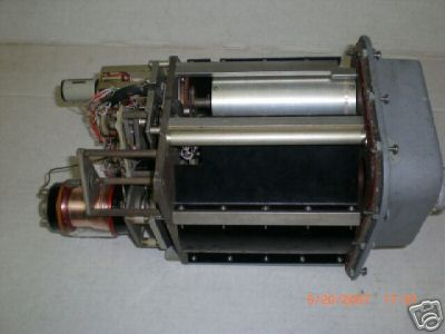
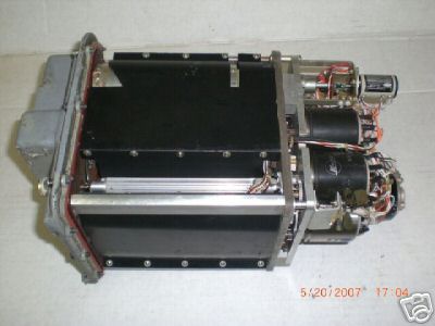
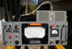
AN/BRA-6 HF tuner for AT-774A/UR submarine emergency whip antenna
2-30 mc
Manual NAVSHIPS 94198
|
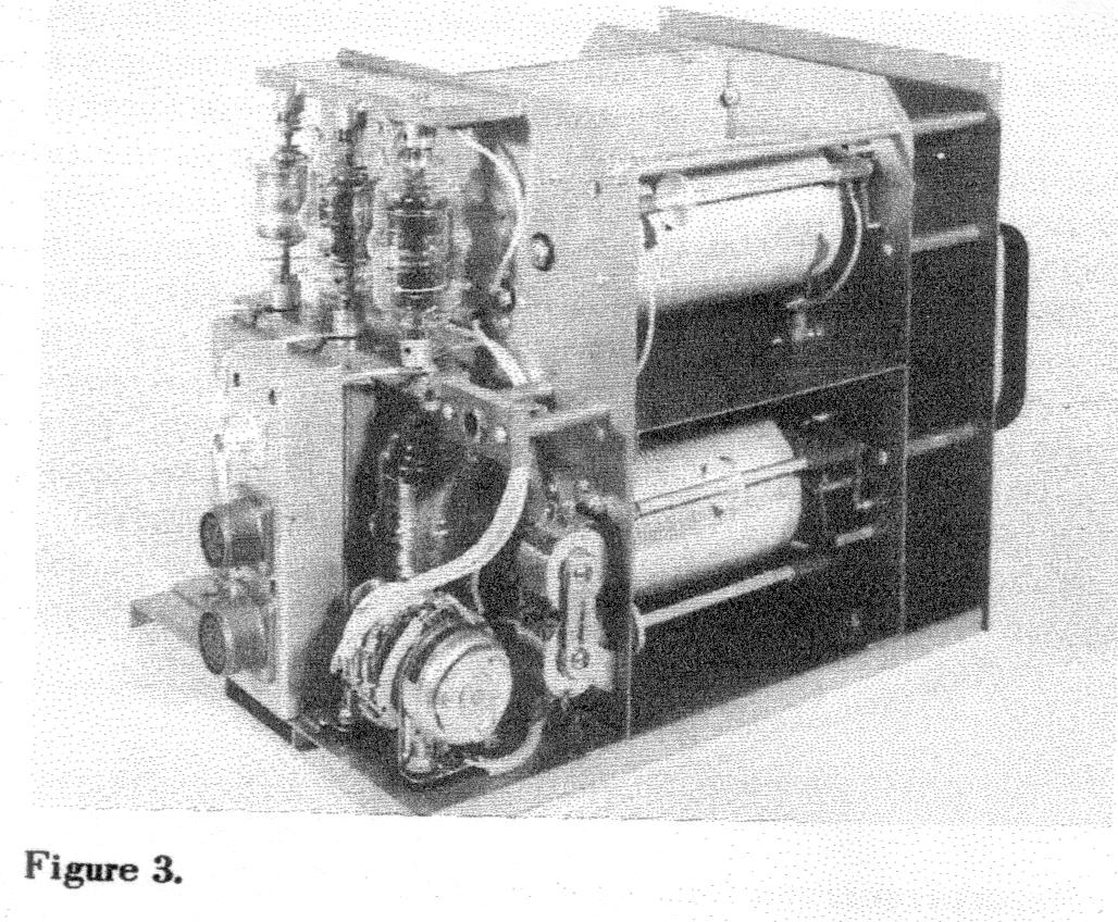
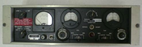
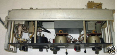
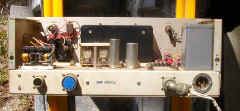
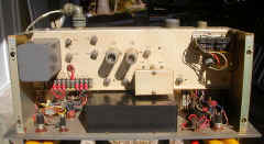
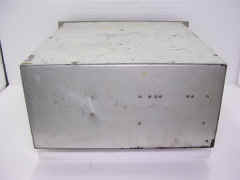
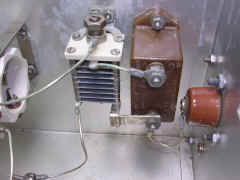
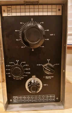
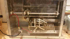
TN-341/BRT Tuner
 |
TN-341/BRT Tuner Schematic

|
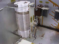
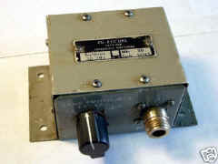
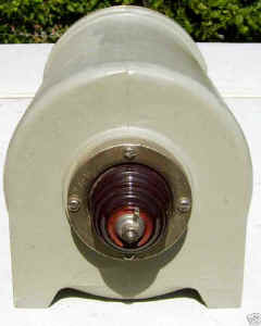
RF-91/BRT Series Coil
(used for 2-6mc)

|
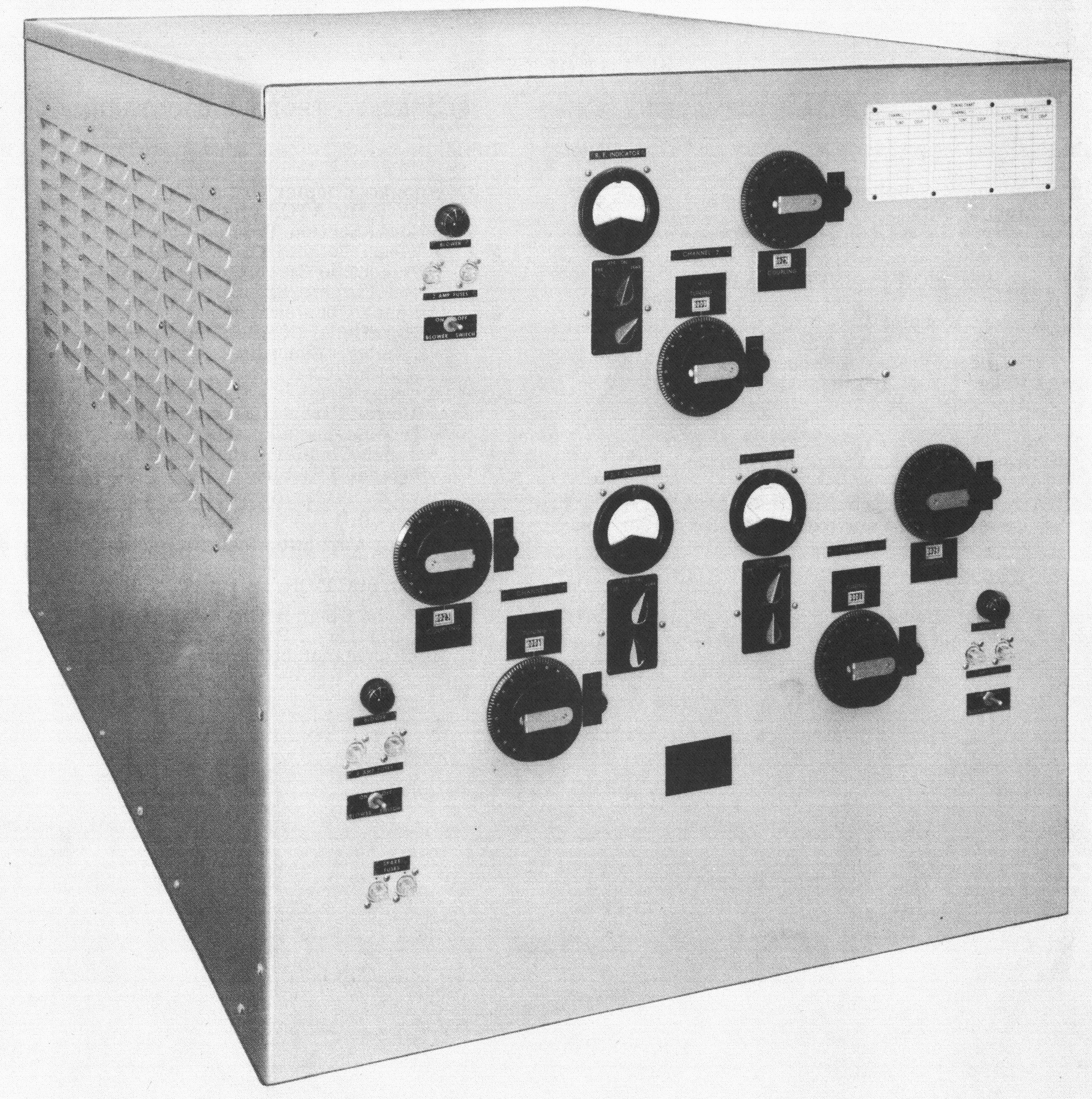
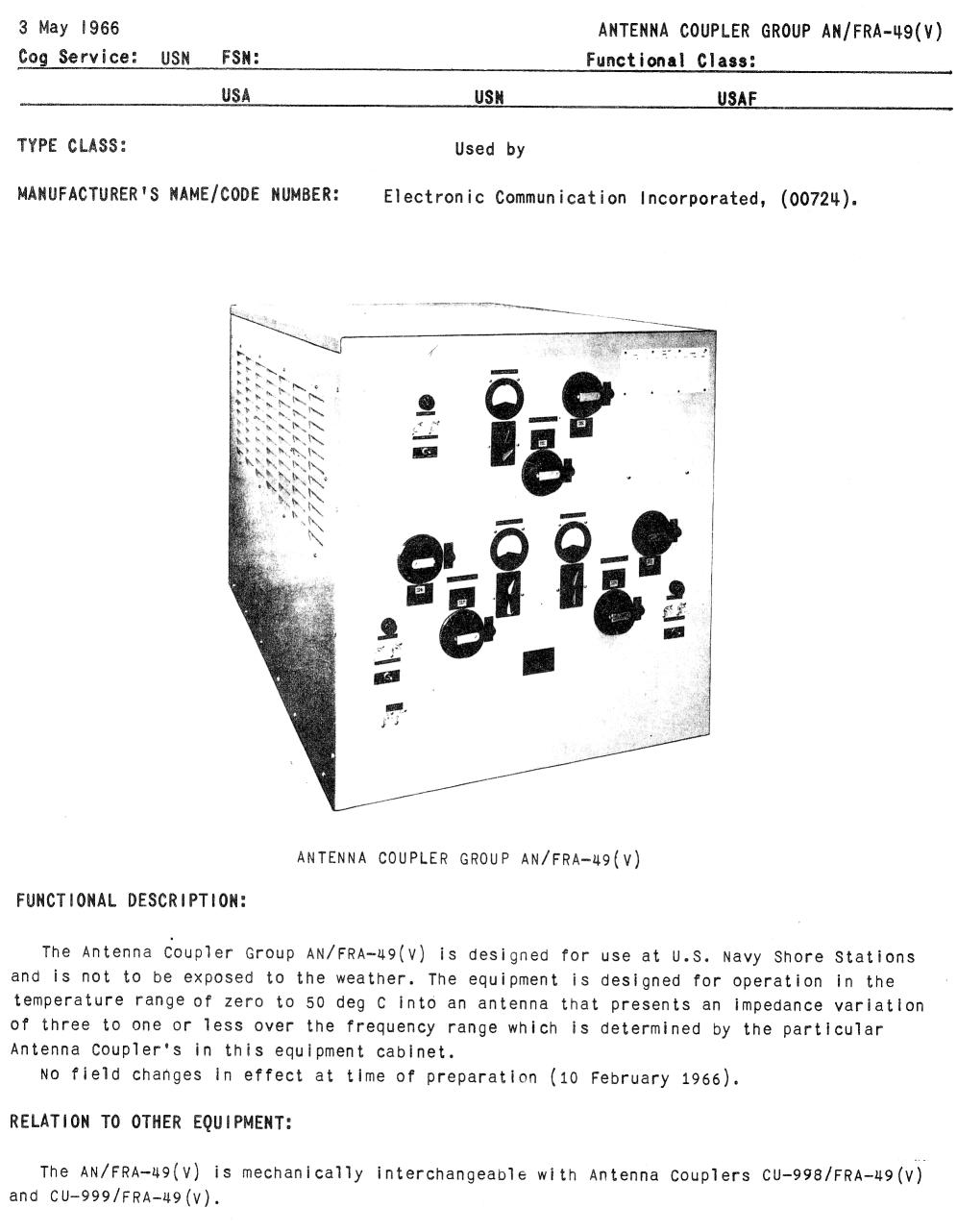
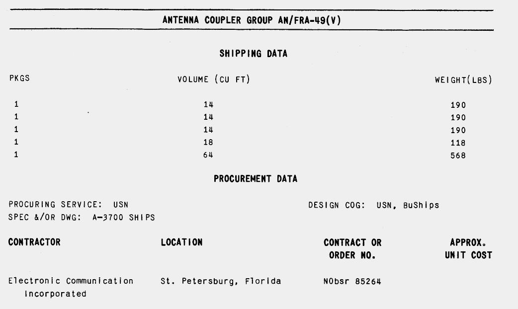
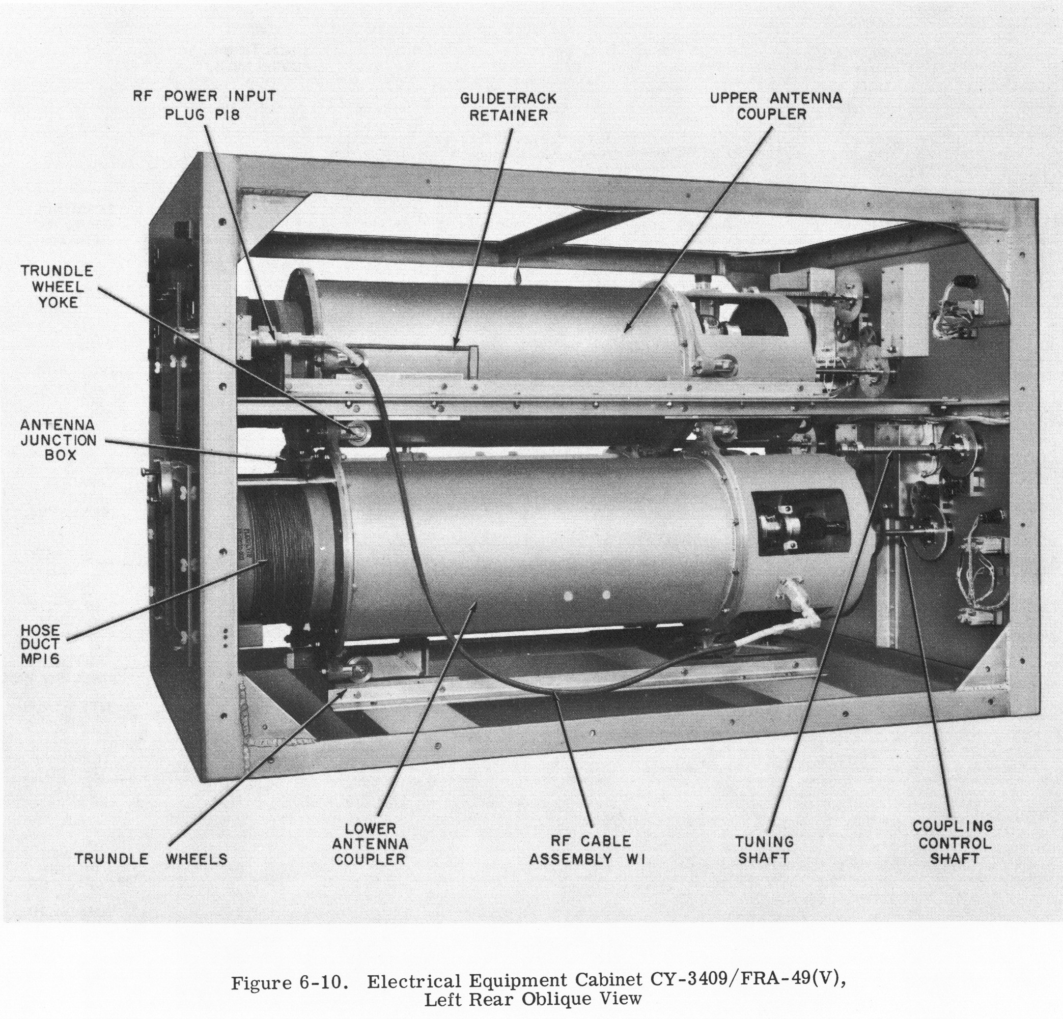
AN/FRA-49(V)
multicoupler

|
|
|
10 KW HF multicoupler
Shore Stations
see NRL development page for
info
Manual - NAVSHIPS 94253
|
|
 |
|
|
|
 |
|
|

|
 |
|
Simplified
Schematic Diagram
Complete
Schematic Diagram
|
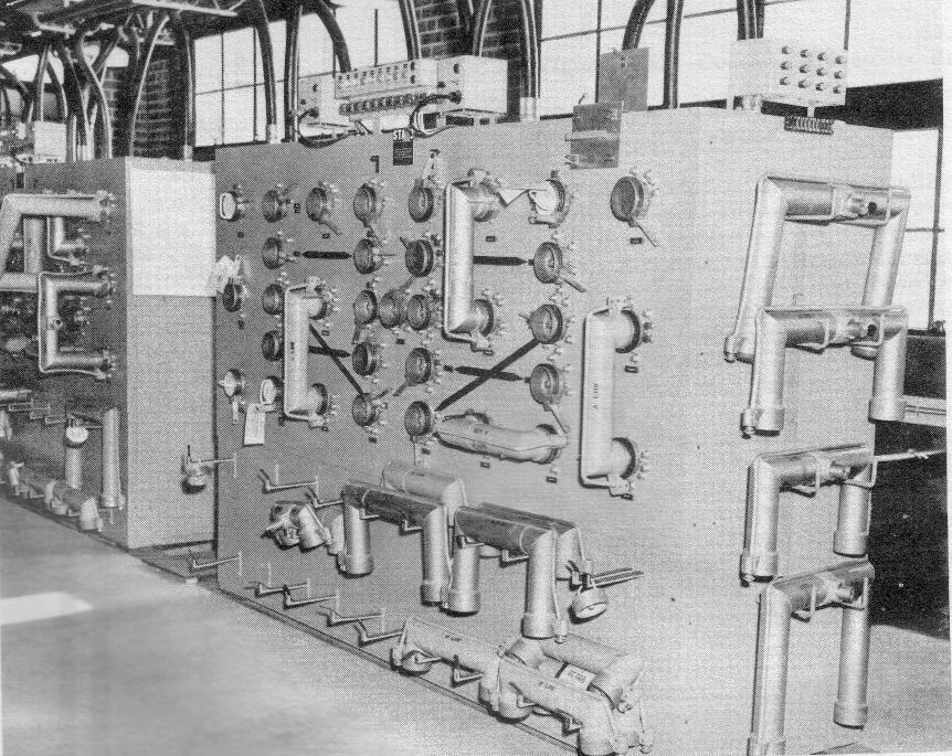
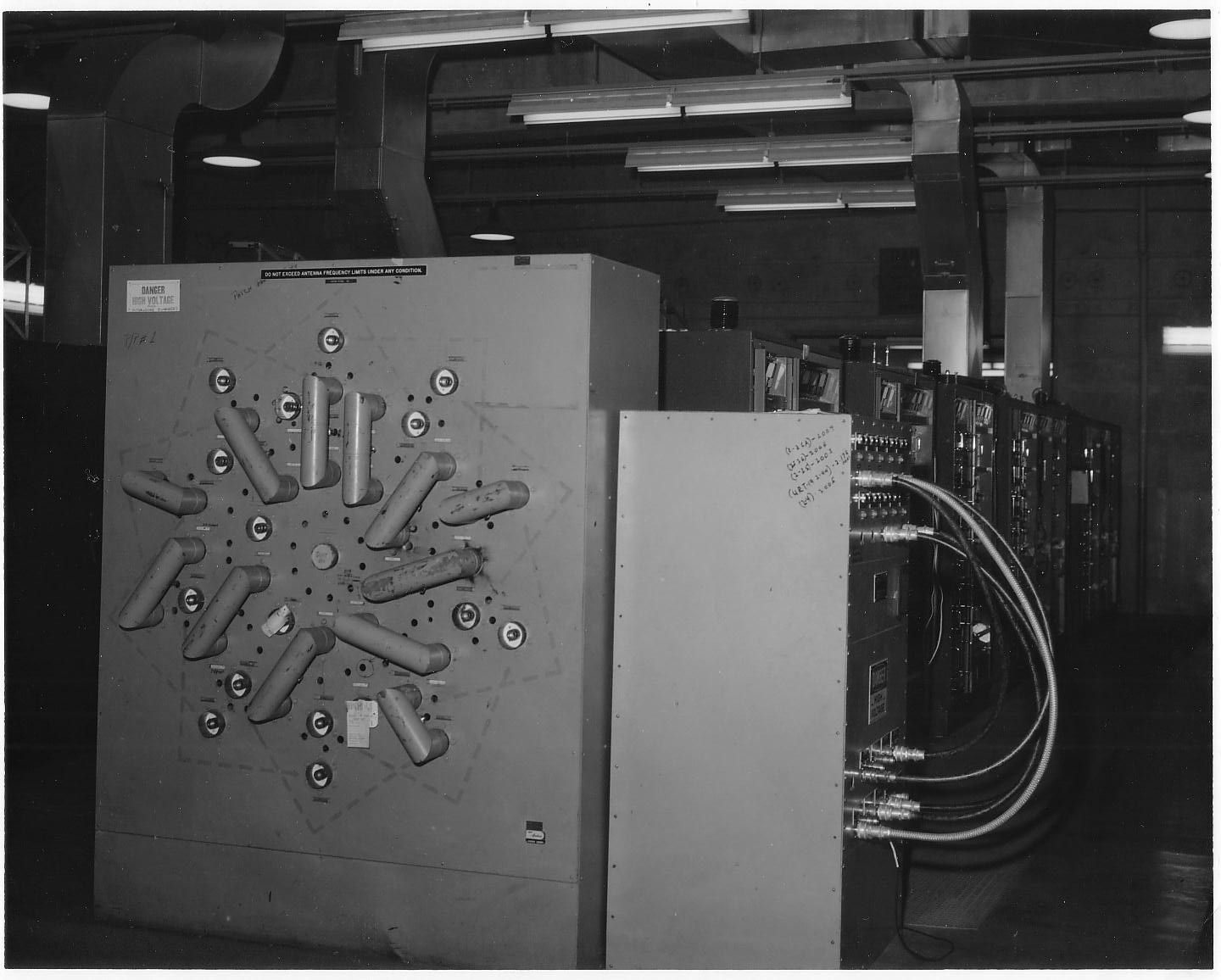
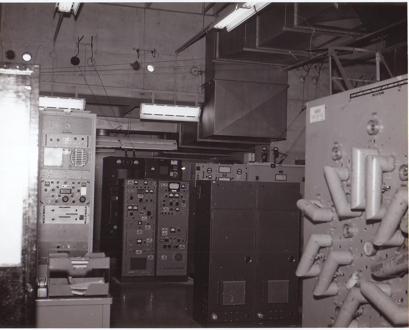
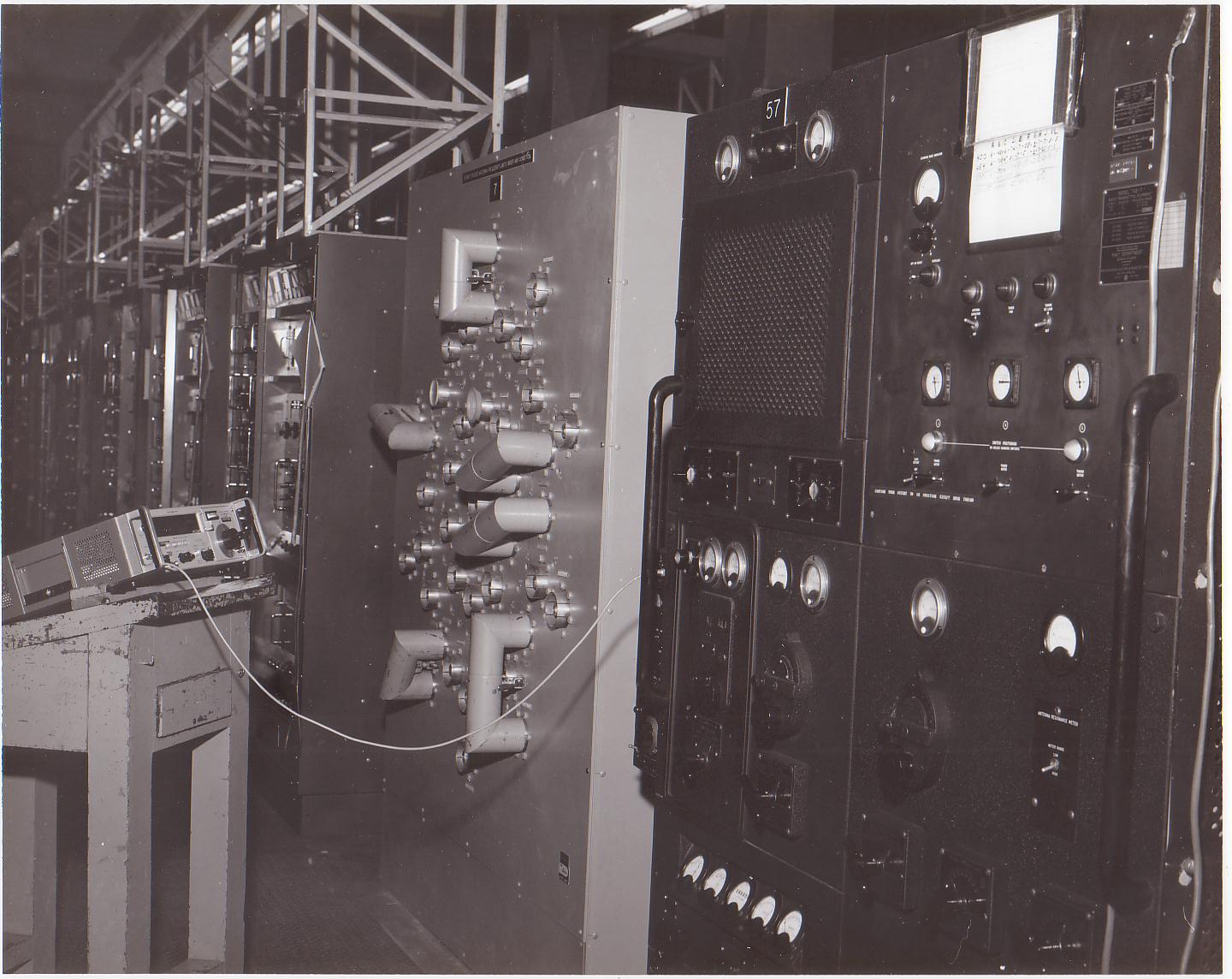
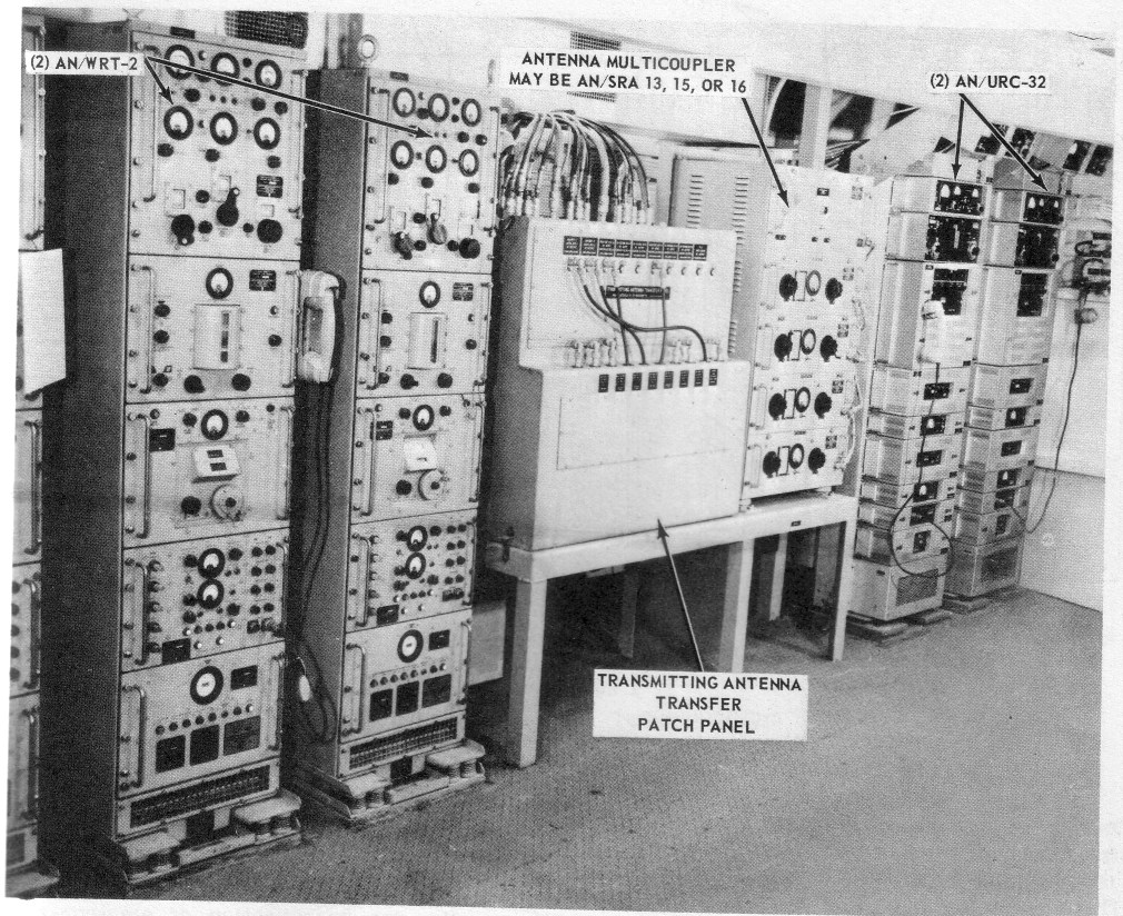
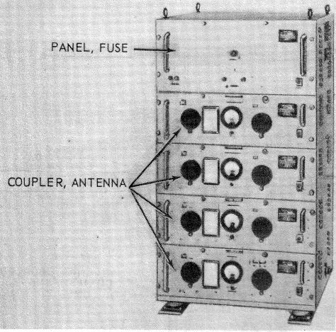
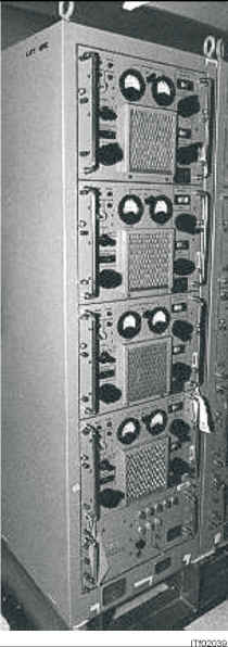
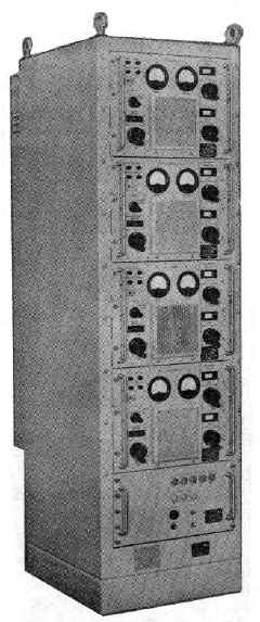
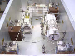
AN/SRA-13
AN/SRA-14
AN/SRA-15
multicouplers
|
four 500 watt inputs to one antenna
xmtrs must be 10% diff in freq.
 |
AN/SRA-13 - 2 to 6 mc
AN/SRA-14 - 4 to 12 mc
AN/SRA-15 - 6 to 18 mc
|
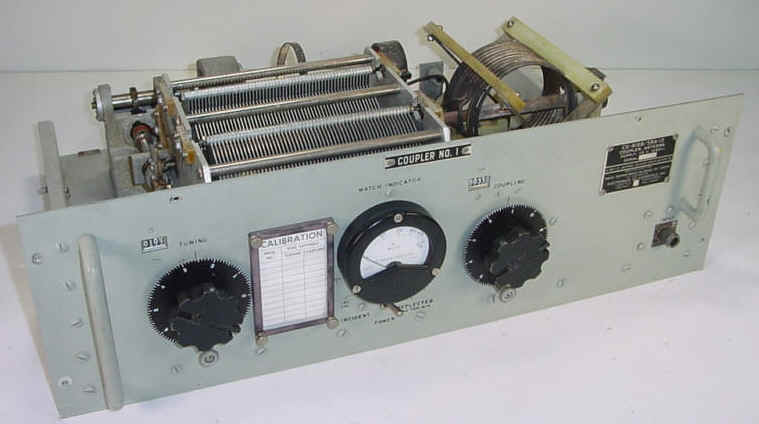
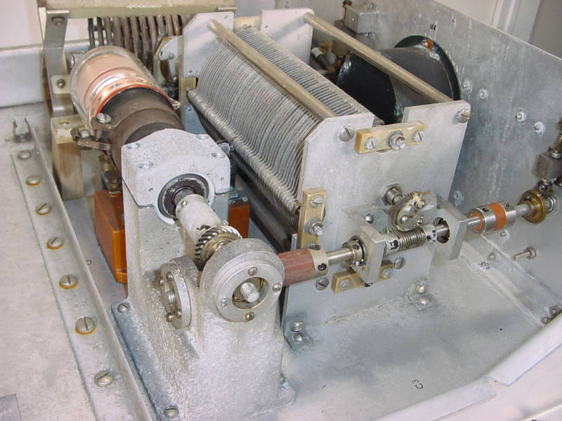
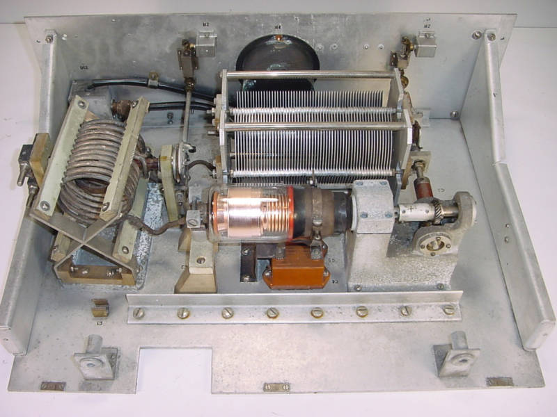
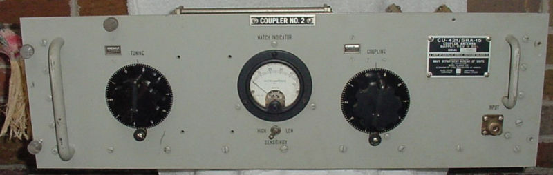
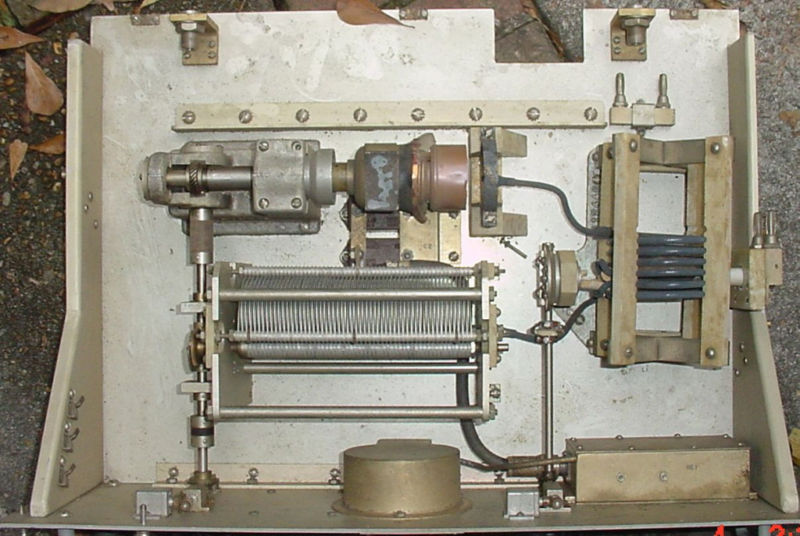
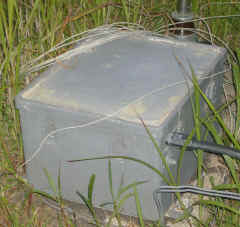
CU-421B/SRA-15 coupler
see NRL development page for
info
SRA-13/14/15 NAVSHIPS 92746
Manuals available from Fair
Radio Sales
|
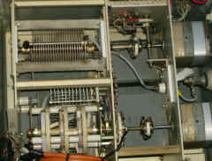
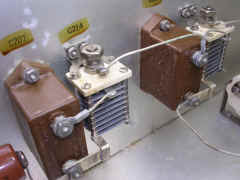
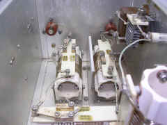
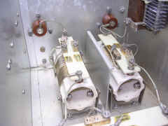
CU-419B/SRA-13 |
CU-419B/SRA-13
|
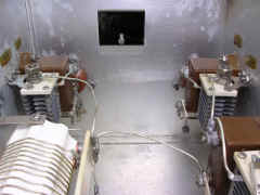
CU-419B/SRA-13 |
CU-419B/SRA-13 |

CU-419B/SRA-13
|
CU-419B/SRA-13 |
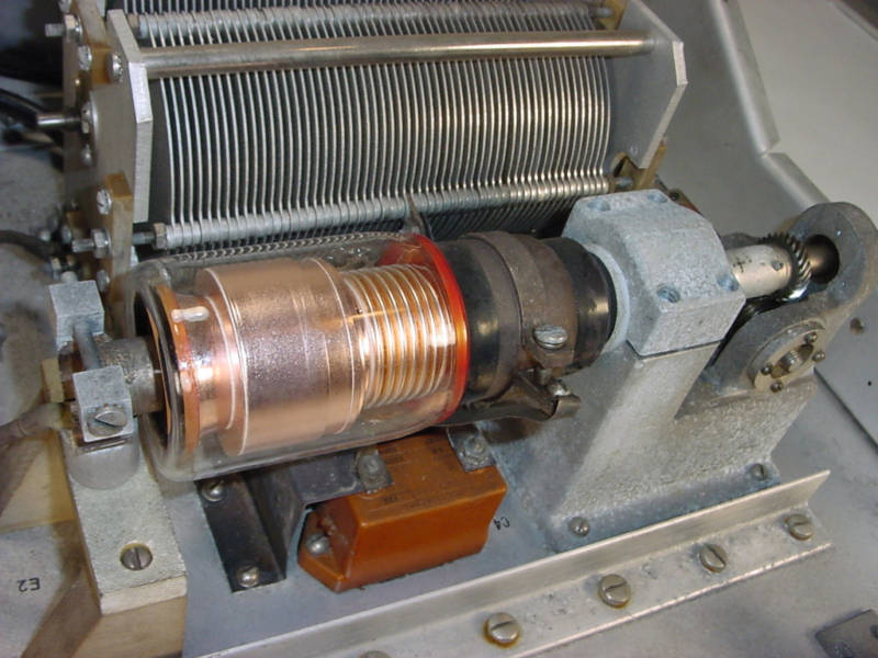
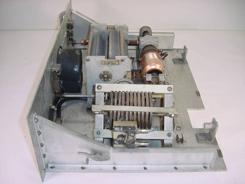
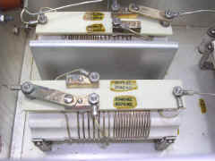
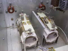
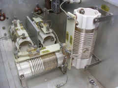
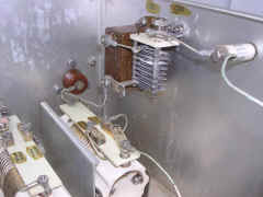
CU-421/SRA-15 |

CU-421/SRA-15 - busted vacuum cap
|
CU-421/SRA-15 - busted vacuum cap |
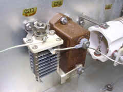
CU-421/SRA-15 |
CU-421/SRA-15
|
CU-421/SRA-15 |
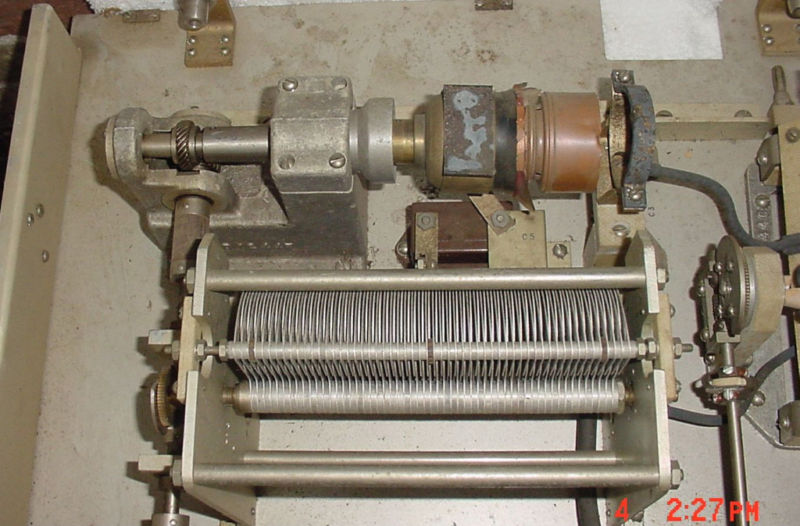
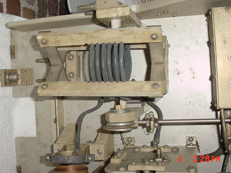
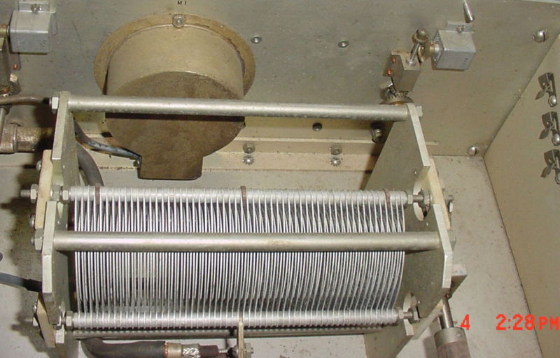
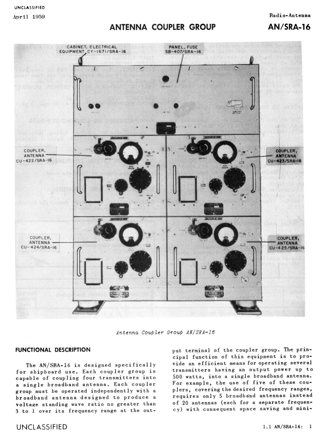
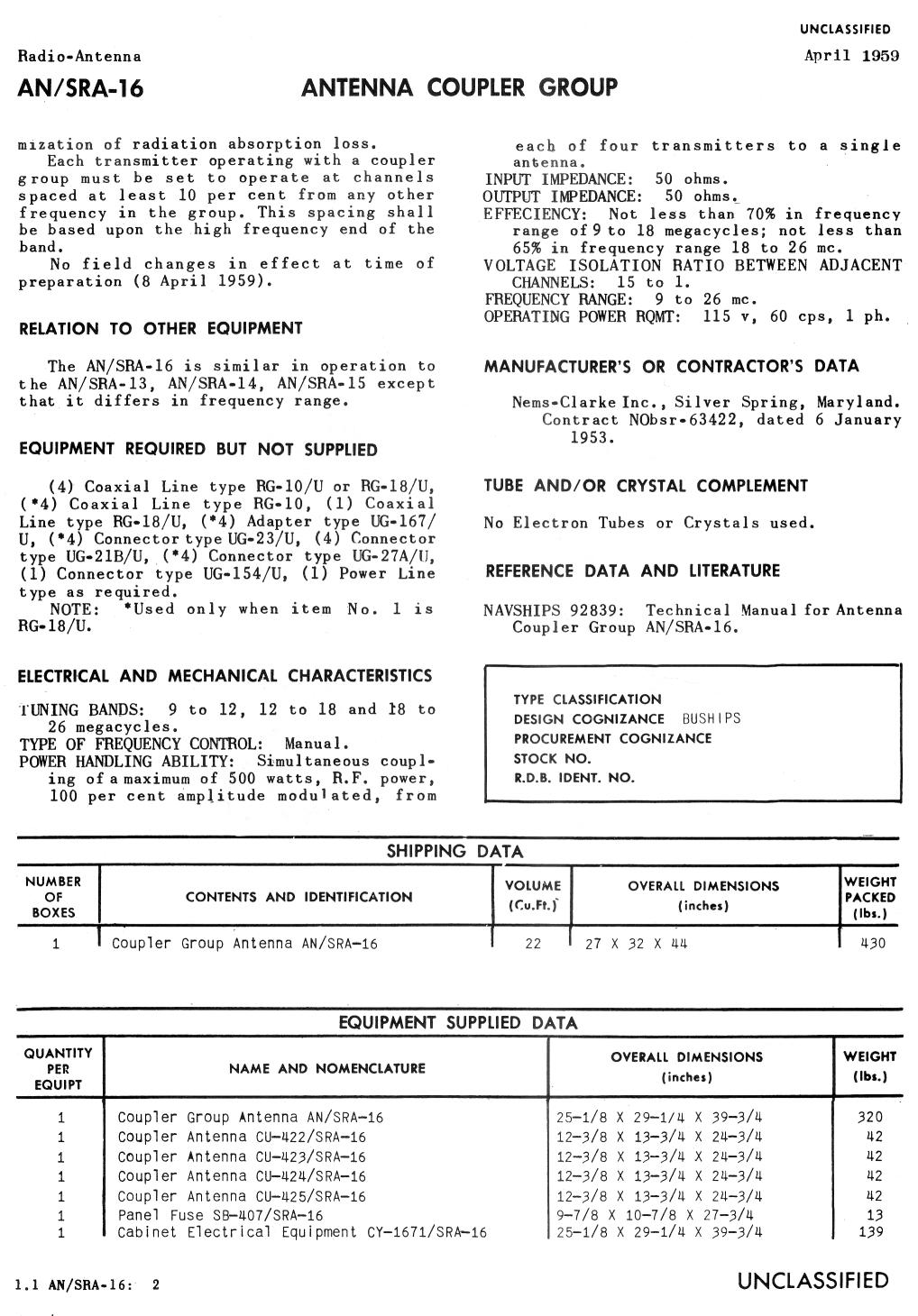
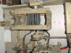
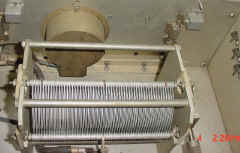
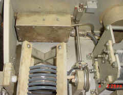
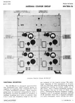
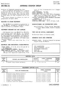
AN/SRA-16
multicoupler
|
|
|
four 500 watt inputs to one antenna
xmtrs must be 10% diff in freq.
9 to 26 mc
see NRL development page for
info
manual NAVSHIPS 92839
|
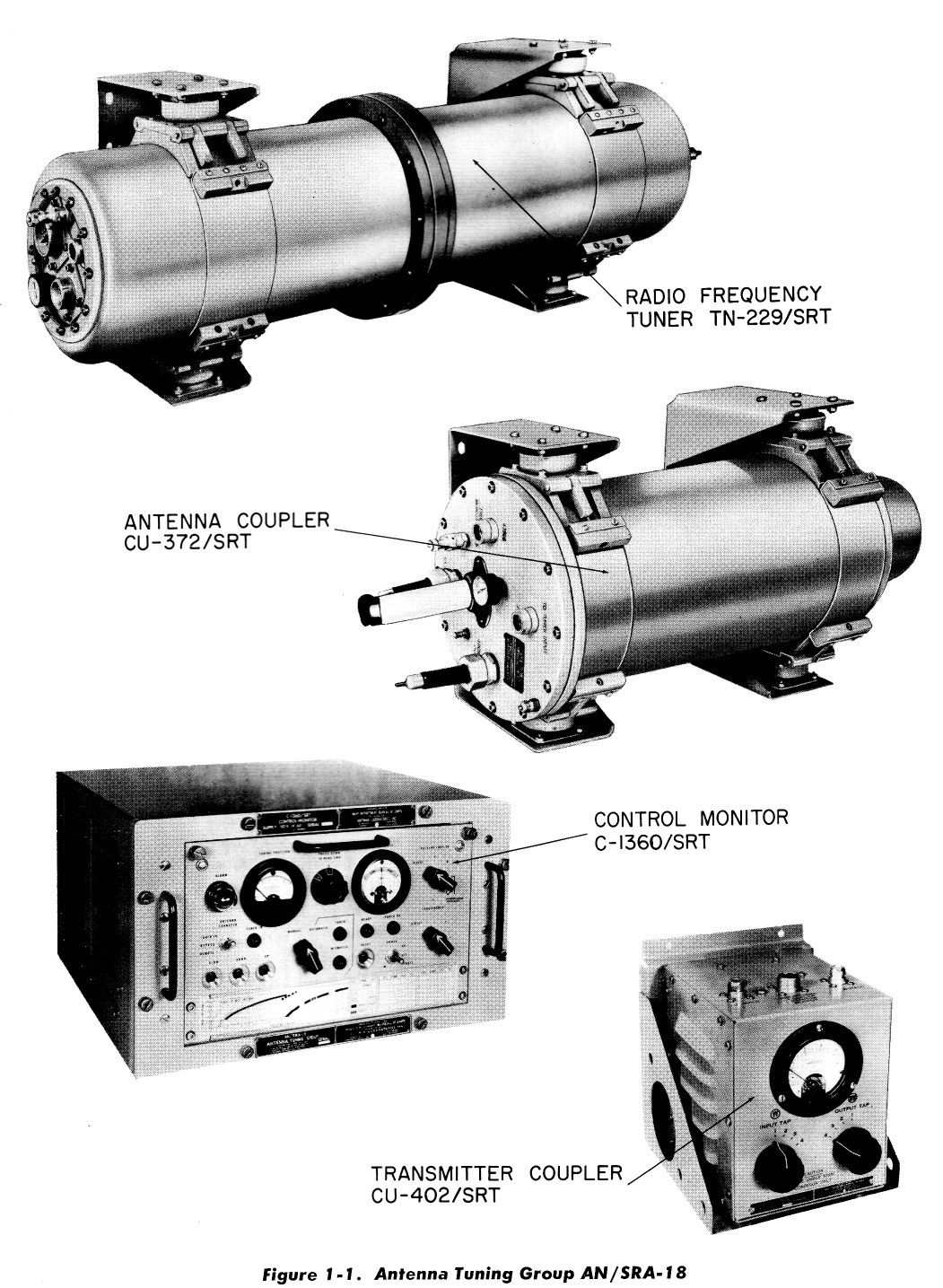
AN/SRA-18
AN/SRA-18A
antenna tuner
|
 |
0.3-30 Mc 500w max system for use with AN/URT-2 series (autotune), AN/SRT-14 series, TBK, and other transmitters
(manual tune)
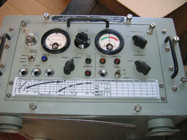
- C-1360/SRT Control Monitor Unit
- CU-402/SRT Transmitter Coupler (impedance transformer)
- CU-372/SRT Antenna Coupler Unit (fixed L, C)
- TN-229/SRT RF Tuner (tunable L)
|
C-1360/SRT Control Monitor Unit
SRA-18 NAVSHIPS 92540
SRA-18A NAVSHIPS 93193
|
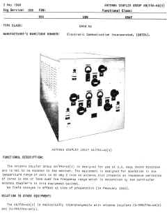
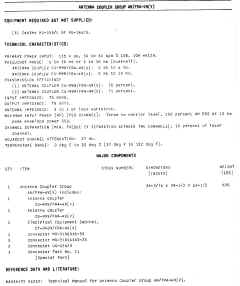
AN/SRA-20
antenna coupler
|
Developed for use with 4-channel RCA SSB-1 transceiver - see
detailed SRA-20 info on SSB-1 page
manual NAVSHIPS 93202
|
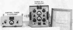
C-2372/SRT controller

|
TN-329/SRT tuner
|
AN/SRA-22
antenna coupler

|
|
CU-714/SRA-22 antenna coupler +
C-2698/SRA-22 coupler control
or C-2494/SRA-22 coupler control
manuf Collins 180R-6
|
Notes on
Operation - PDF
Operation With 35' Whip - PDF
NAVSHIPS 93286
NAVSHIPS 0967-136-6010
|
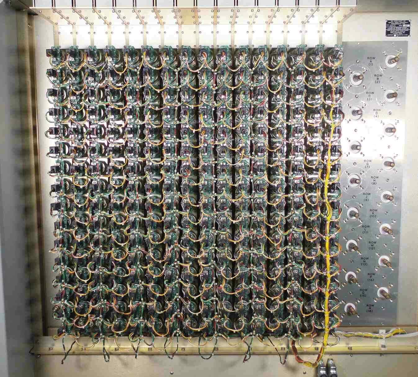
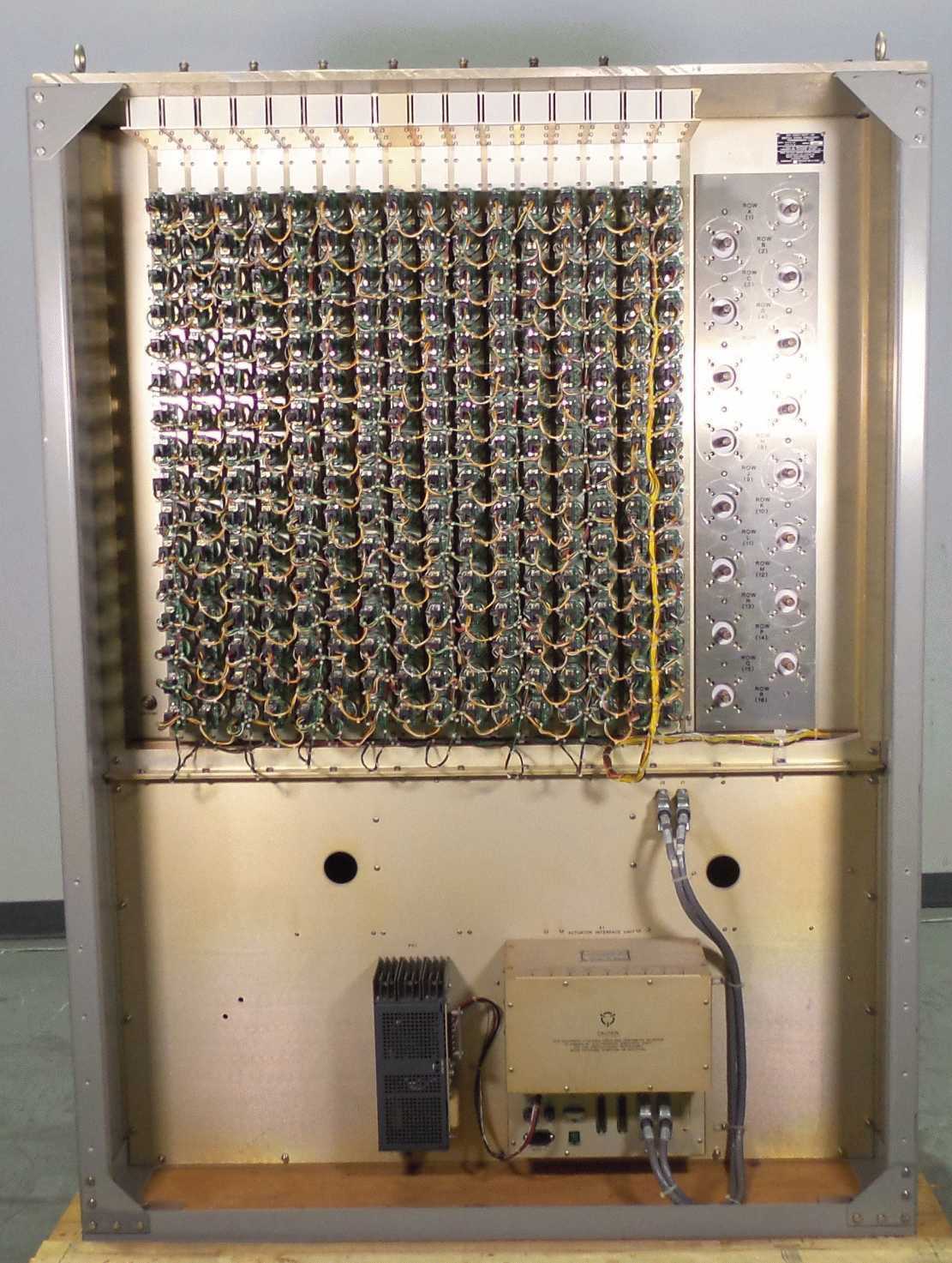
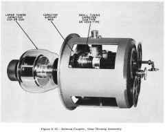
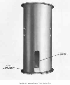
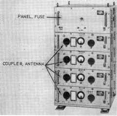
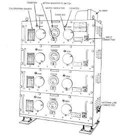
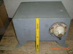
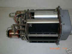
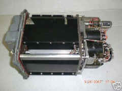
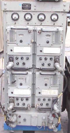
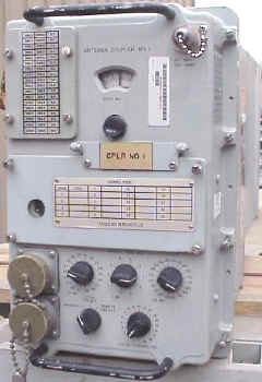
AN/SRA-23
multicoupler
|
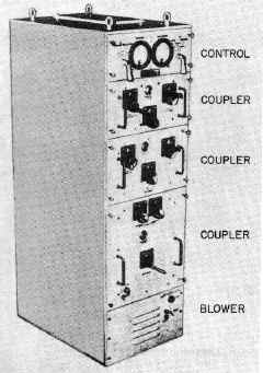 |
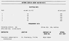
Antenna multicoupler AN /SRA-23
consists of three couplers and associated control and blower units. The
couplers cover the frequency range 2 to 27 mc in three frequency bands.
Each coupler operates in a different band. These bands are 2 to 6 mc, 5 to
15 mc, and 9 to 27 mc. The coupler group was developed for use with
500-watt transmitters, but, with minor adjustments. it is capable of
handling transmitters with 1000-watt outputs.
One coupler group accommodates only one transmitter.
Provisions are made, however, for connecting up to eight of these groups
together to form a multicoupler system. This arrangement permits the
simultaneous operation of eight transmitters into a single broadband
antenna.
Manual NAVSHIPS 93196
|
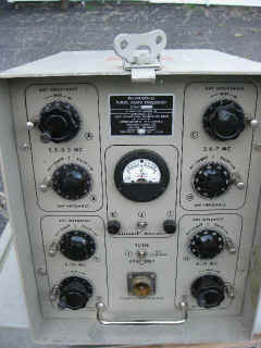
AN/SRA-25
antenna coupler
TN-348 + C-2977
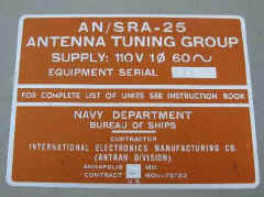
Specification sheets
Please send e-mail if you have
any more info
|
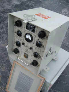 |
4-channel HF tuner developed for use with
Eldico S-100 transceiver. Replaces Eldico M-100. Appears similar to AN/SRA-20.
|

|
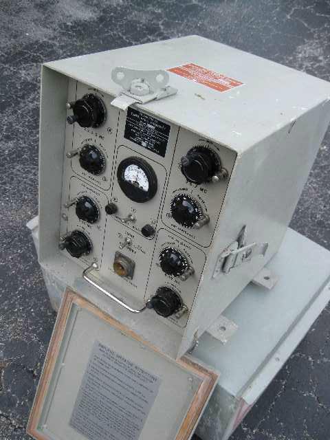
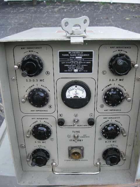
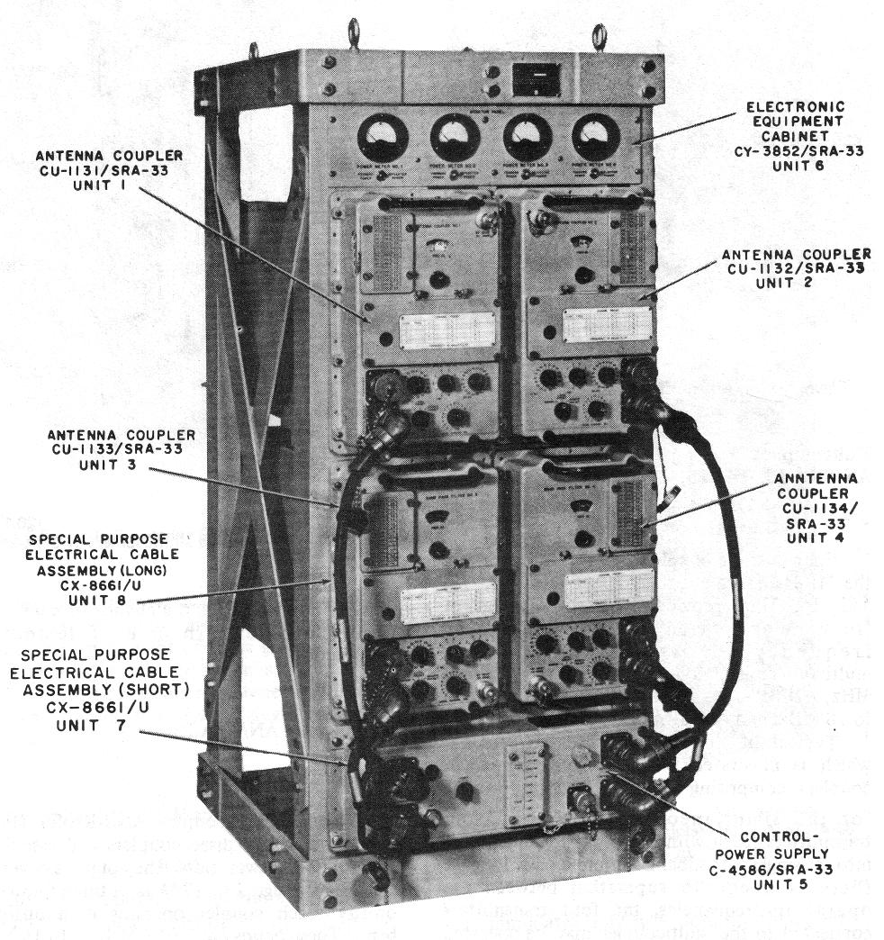
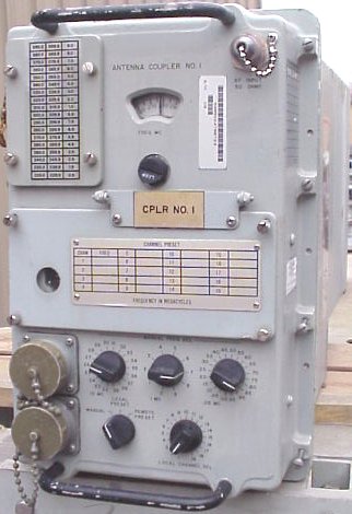
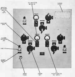
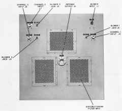
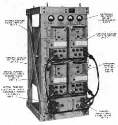
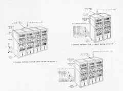
AN/SRA-33
UHF antenna multicoupler
|
 |
4 couplers, 225-400 MHz, 140 watts
uses C-4586/SRA-33 control/power supply
The AN/SRA-33 is designed for
operation with shipboard radio
set AN/WSC-3.
units and manuals are available from Fair
Radio Sales
|
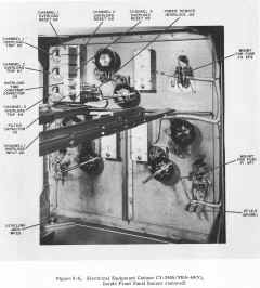
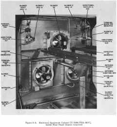
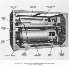
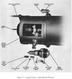
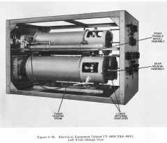
The AN/SRA-33 consists
of four antenna couplers (CU-1131/SRA-33
through CU-1134/SRA-33), a control power supply
C-4586/SRA-33, an electronic equipment
cabinet CY-3852/SRA-33, and a set of special-purpose
cables.
|
|
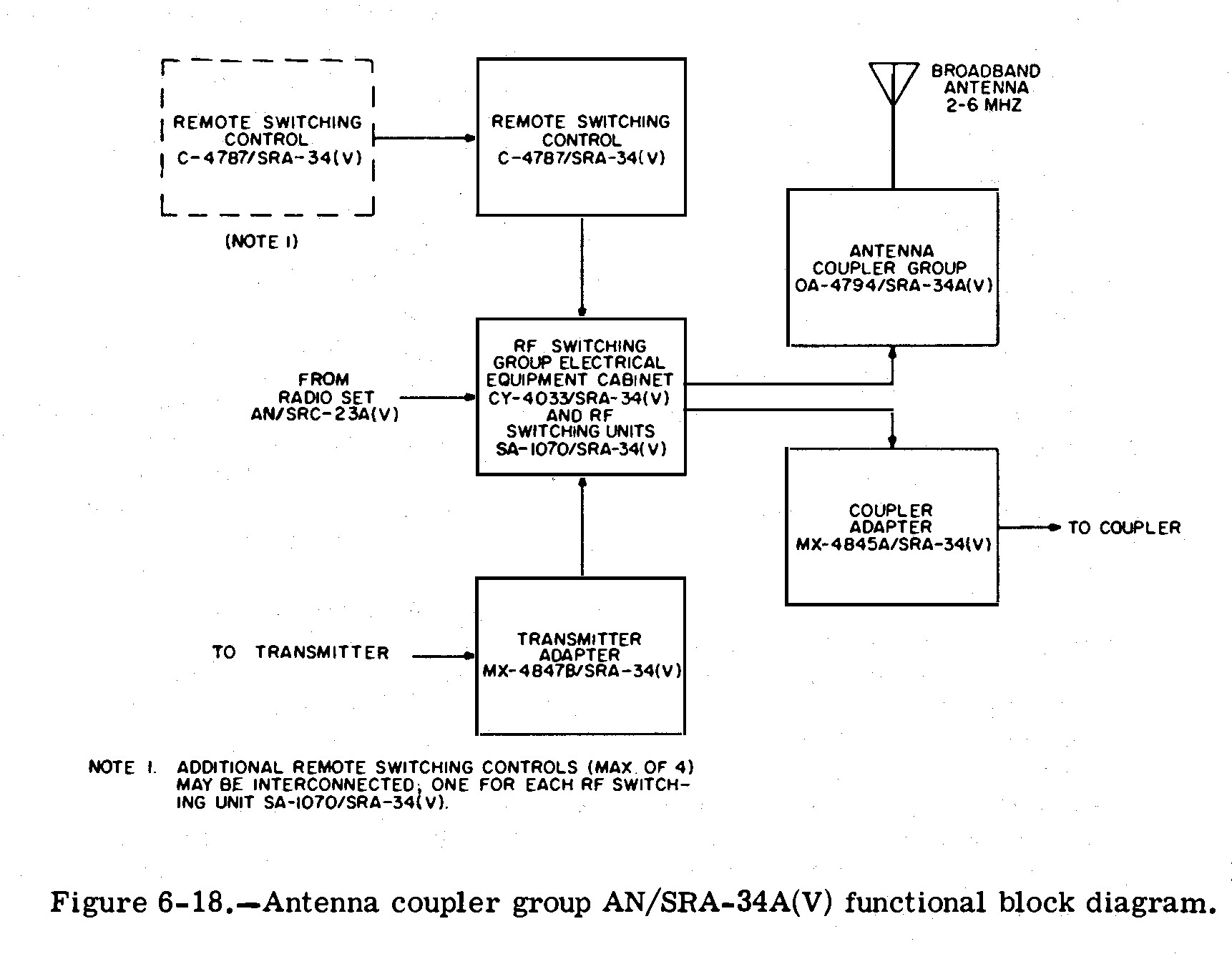
AN/SRA-34 information
Download CU-1169 manual
|
C-4787/SRA-34
 |
C-4787/SRA-34

|
 |
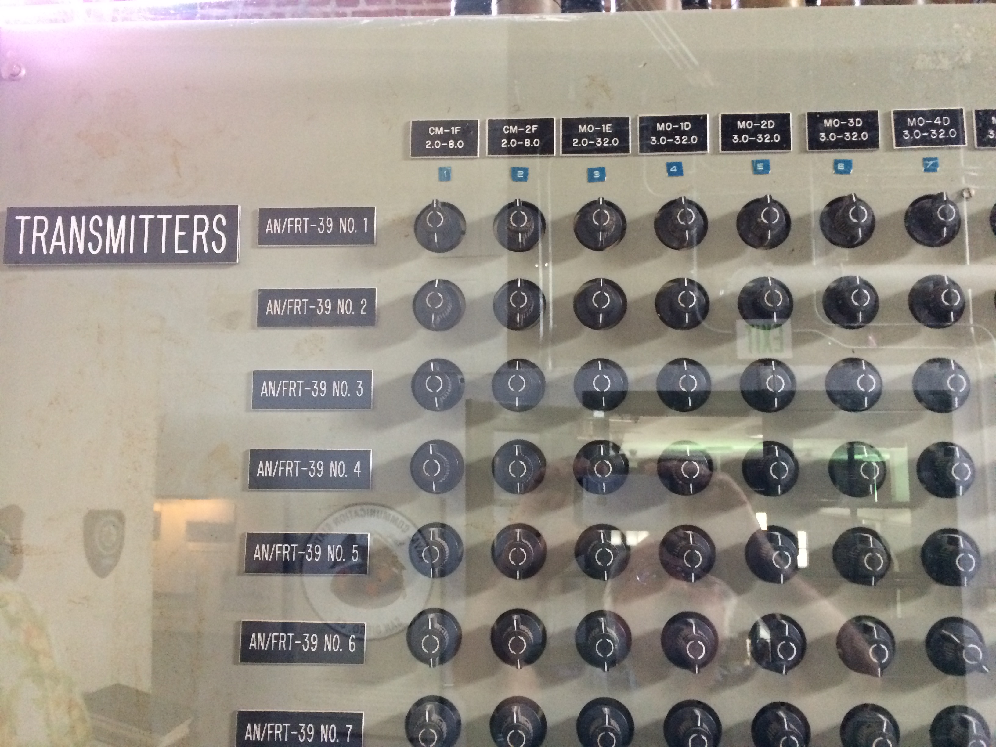
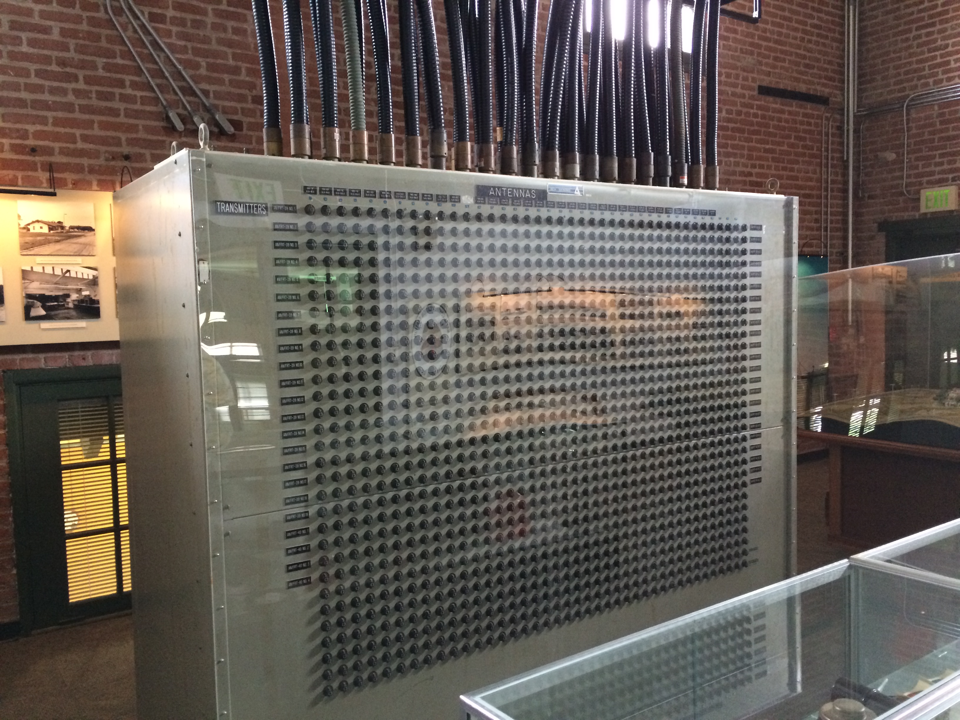
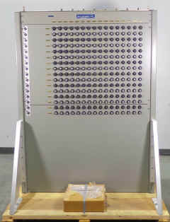
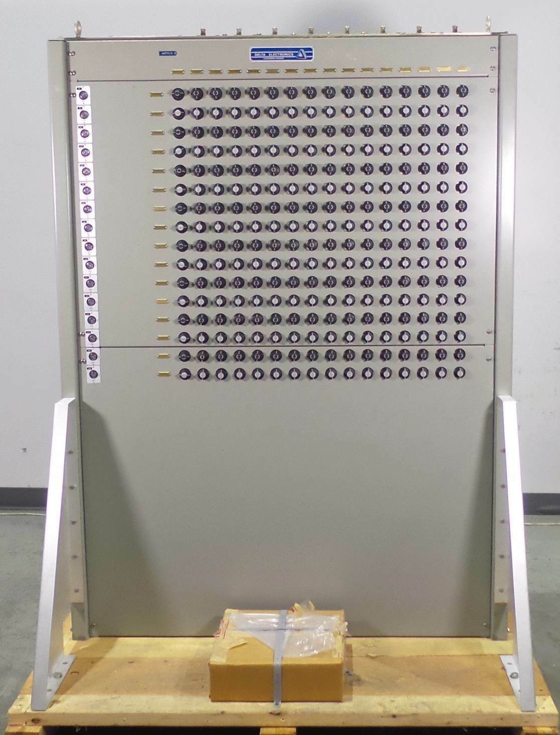
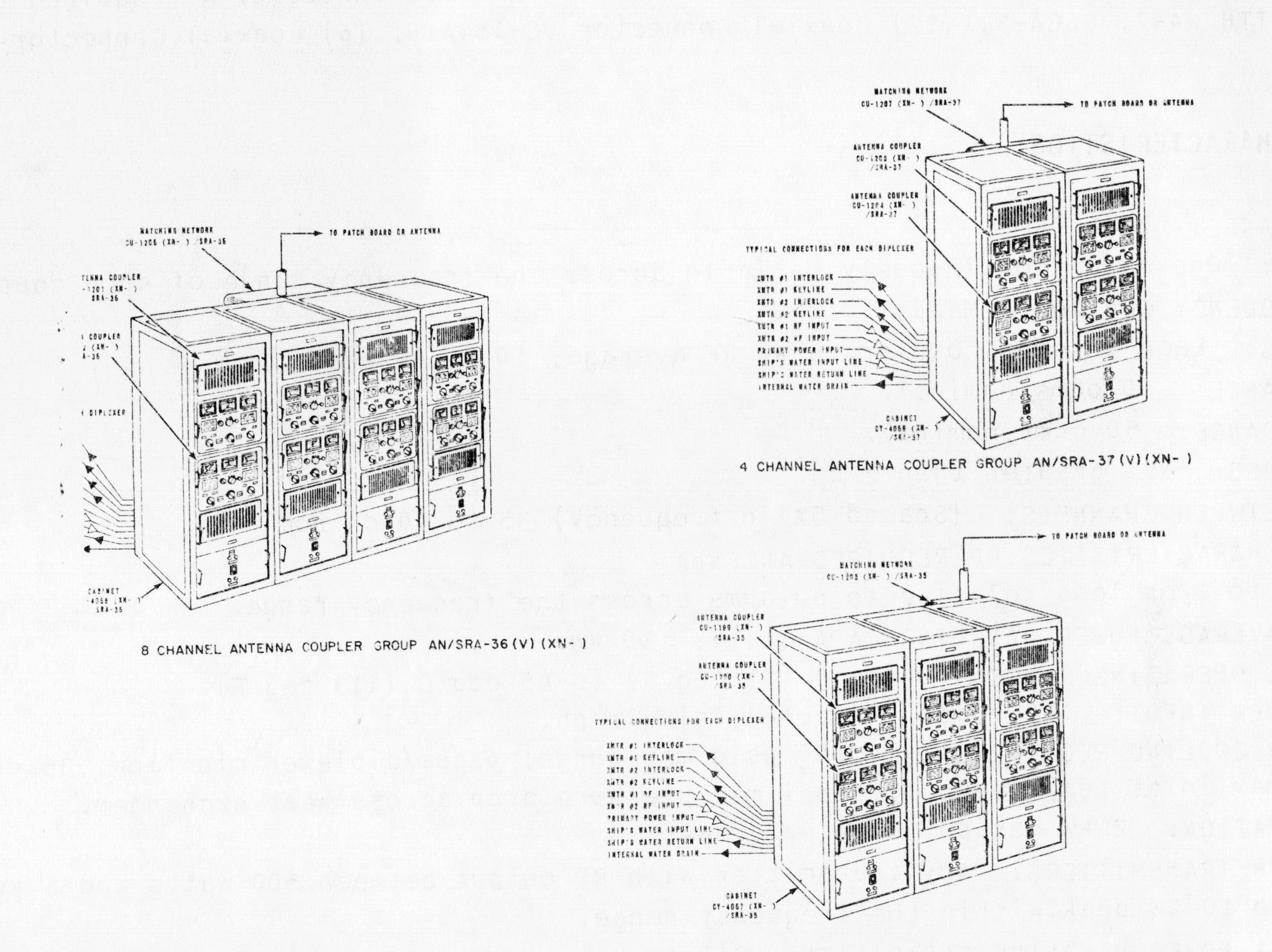
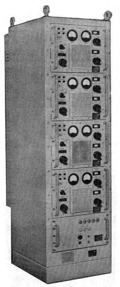
AN/SRA-35
AN/SRA-36
AN/SRA-37
HF Multicouplers
10 KW HF multicouplers
for Communications Ships
|
need better photos
|
Aboard USS Arlington AGMR-2
|
Spec sheets
see NRL development page
for info
|
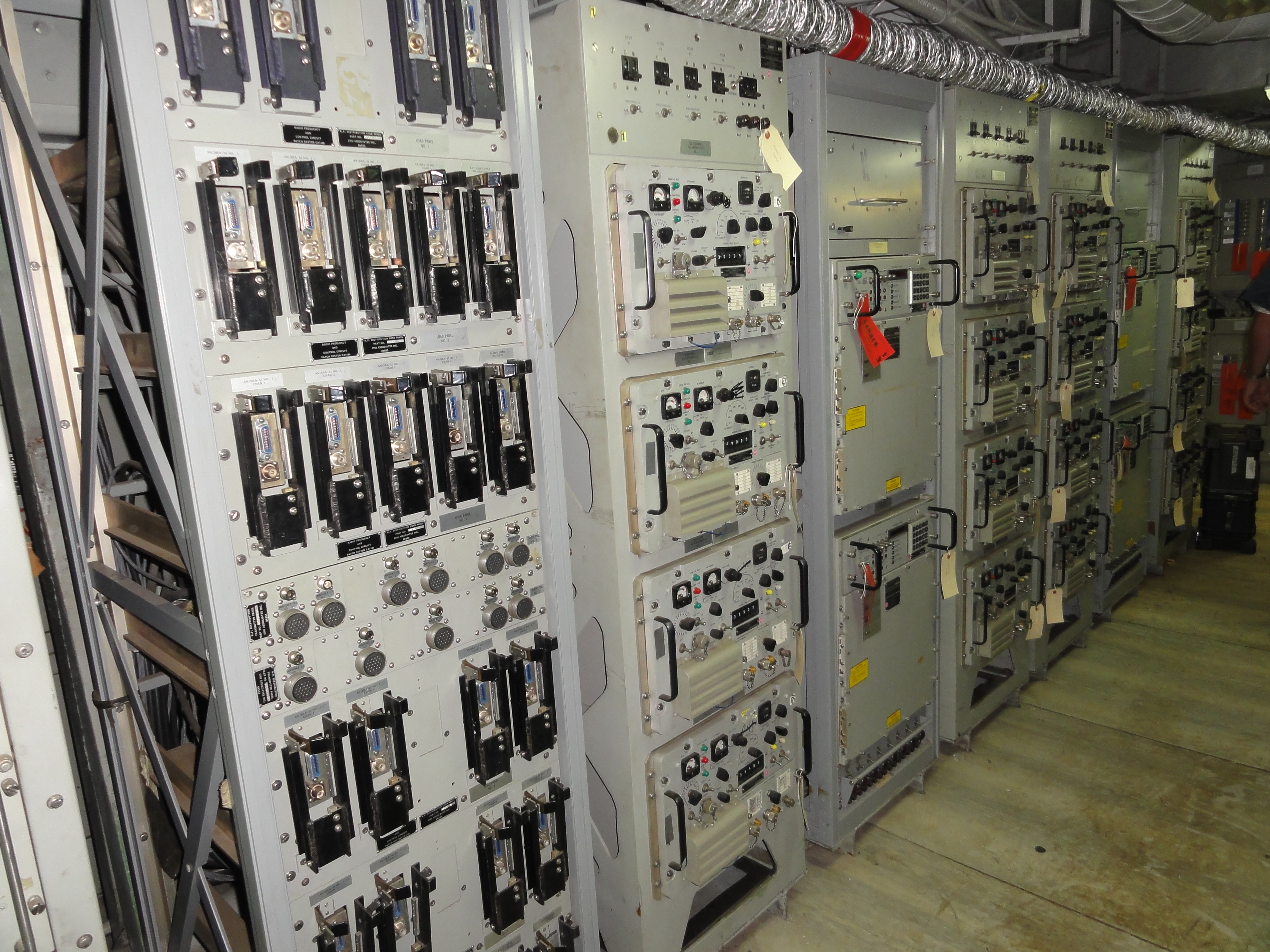
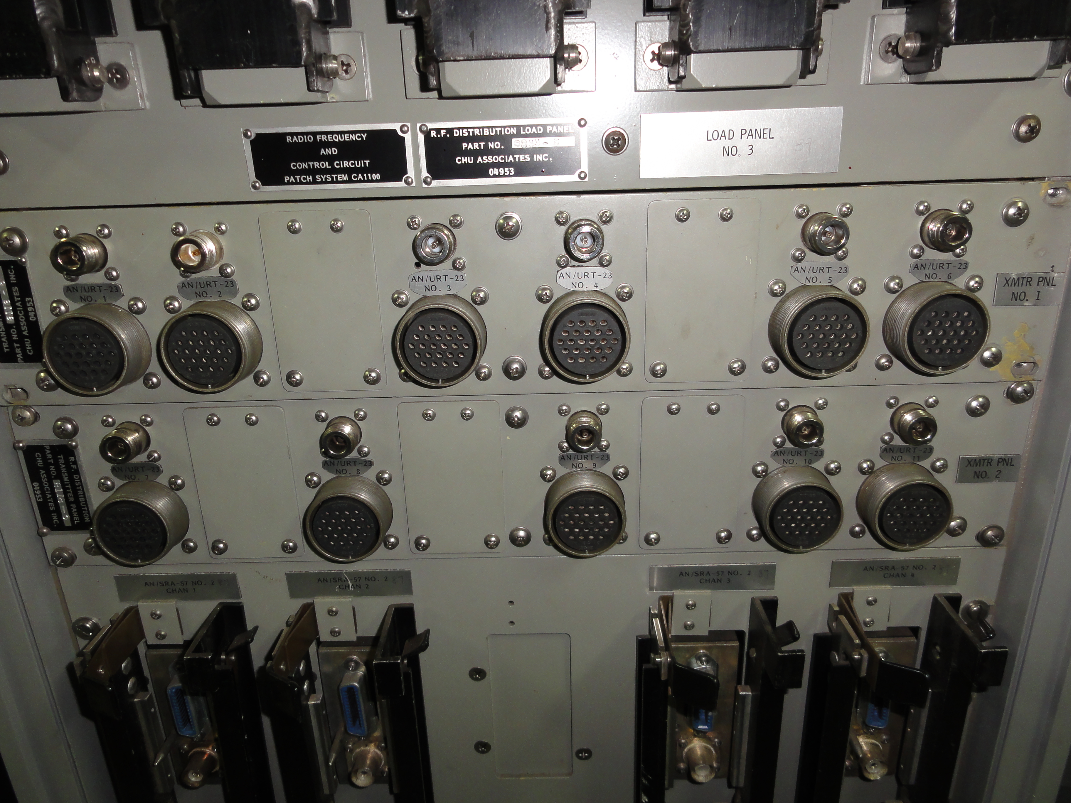
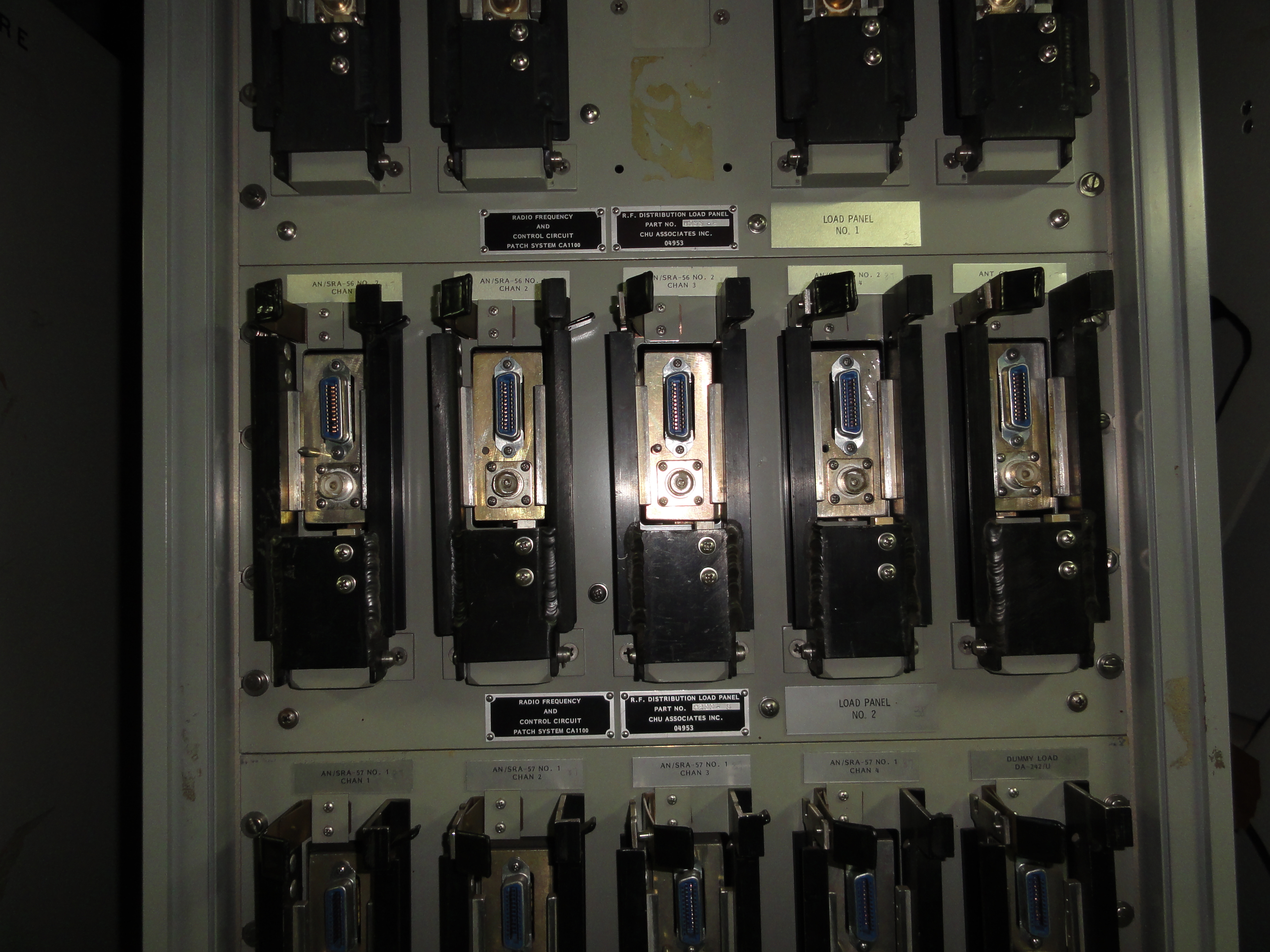
AN/SRA-56
AN/SRA-57
AN/SRA-58
Multicoupler
|
 |
1kw (2kw PEP) per input
|
components -
AN/SRA-56 (2-6mc)
four CU-1772/SRA-56 coupler units
PP-4993/SRA power supply
CV-6422/SRA-56 cabinet
CU-1773/SRA-56 matching network
(to add four more coupler units)
AN/SRA-57 (4-12mc)
four CU-1774/SRA-57 coupler units
PP-4993/SRA power supply
CV-6422/SRA-57 cabinet
CU-1773/SRA-57 matching network
(to add four more coupler units)
AN/SRA-58 (10-30mc)
four CU-1776/SRA-58 coupler units
PP-4993/SRA power supply
CV-6422/SRA-58 cabinet
Specification
document
Manuals available from Fair Radio
Sales
need more info!! - see also tuner section of Shipboard
Equipment Manual |
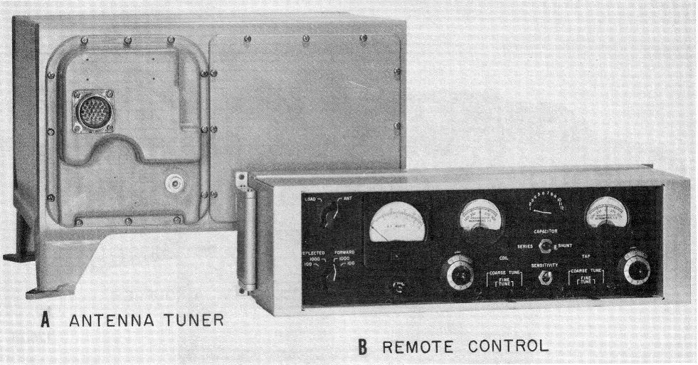
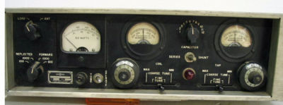
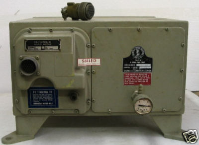
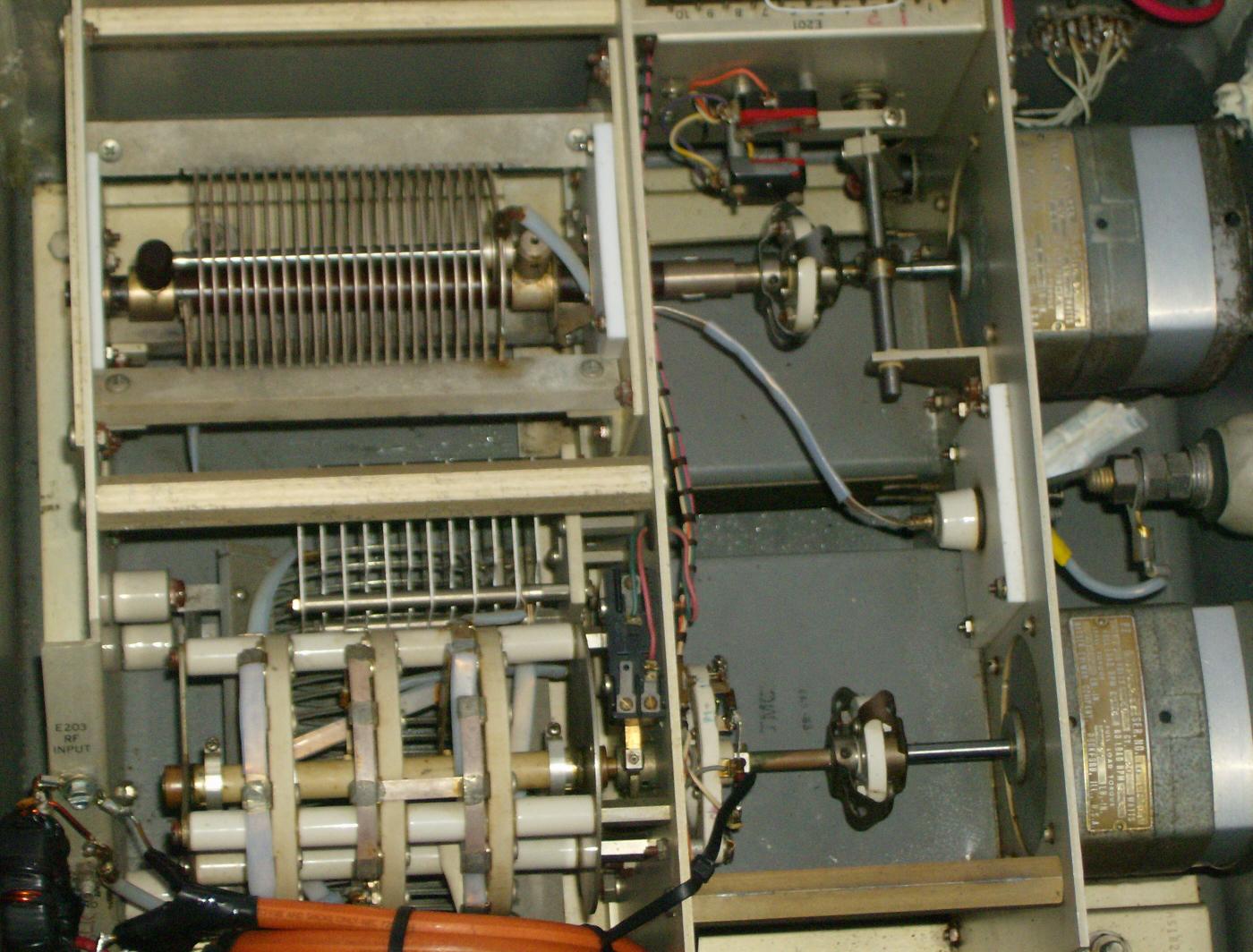
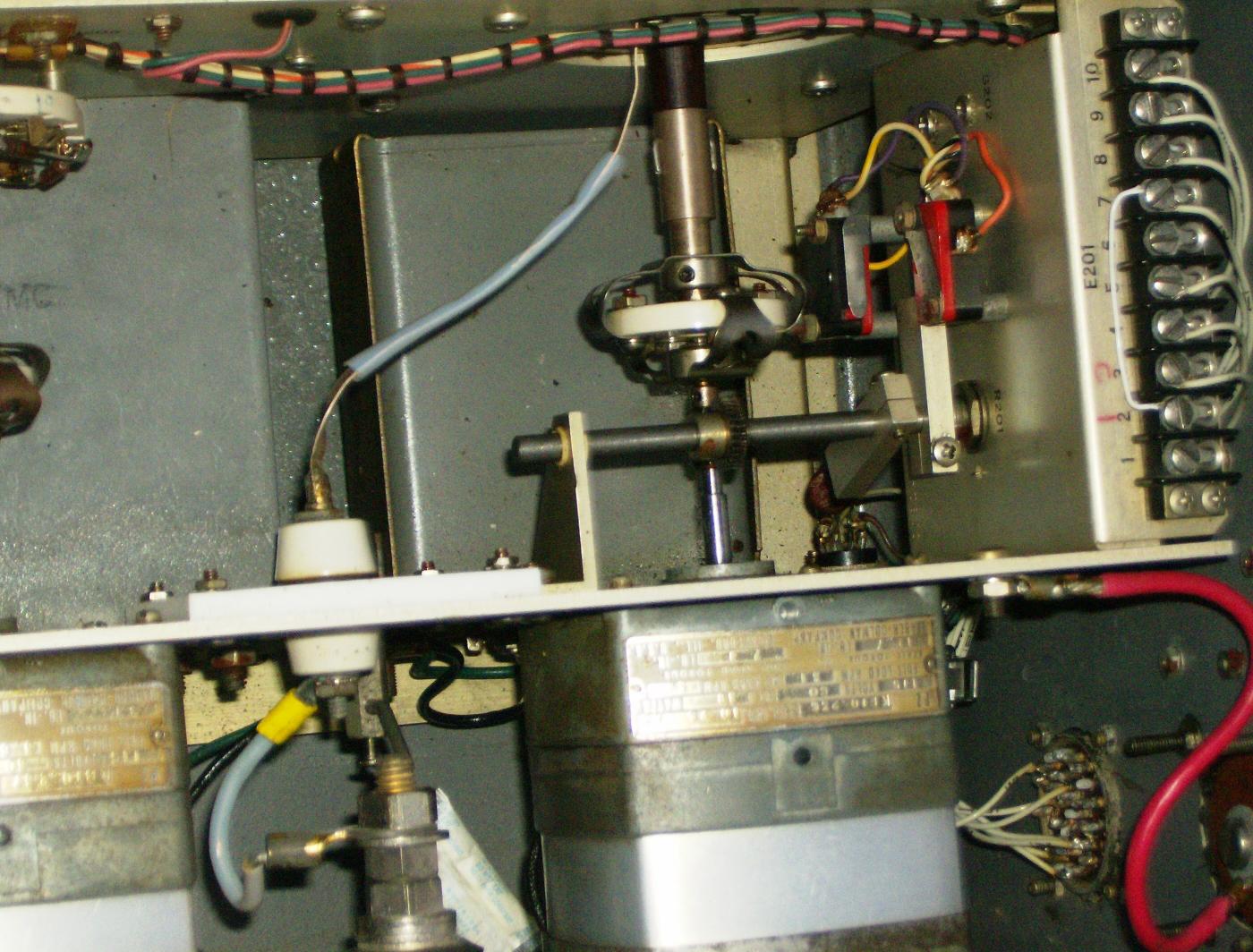
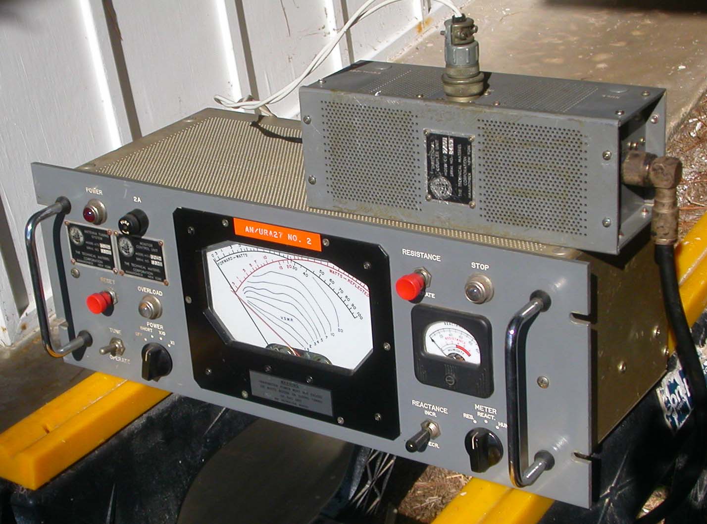
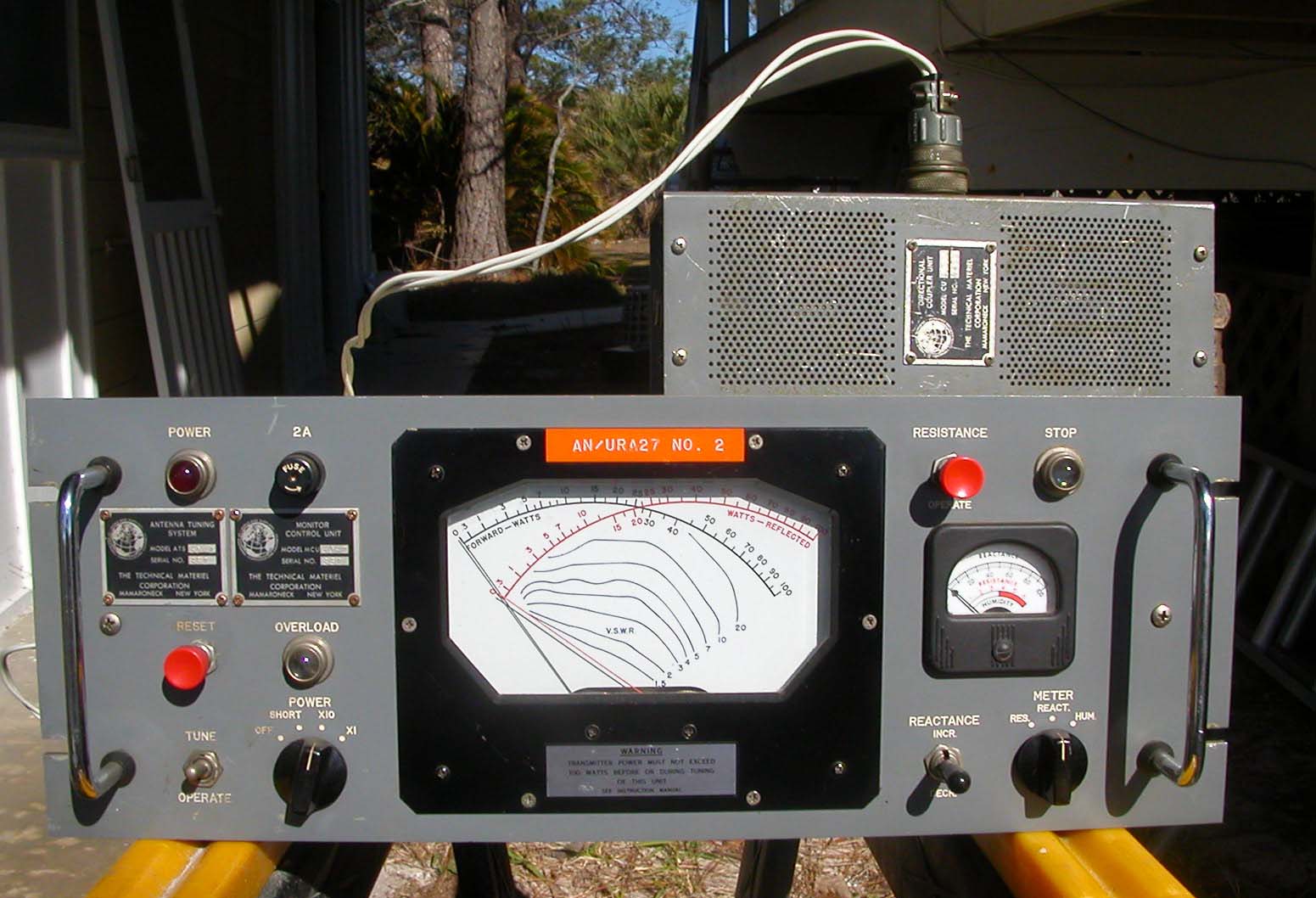
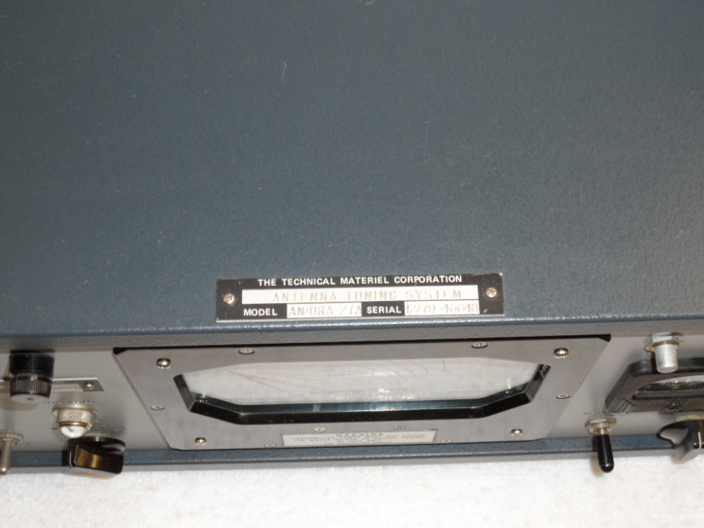
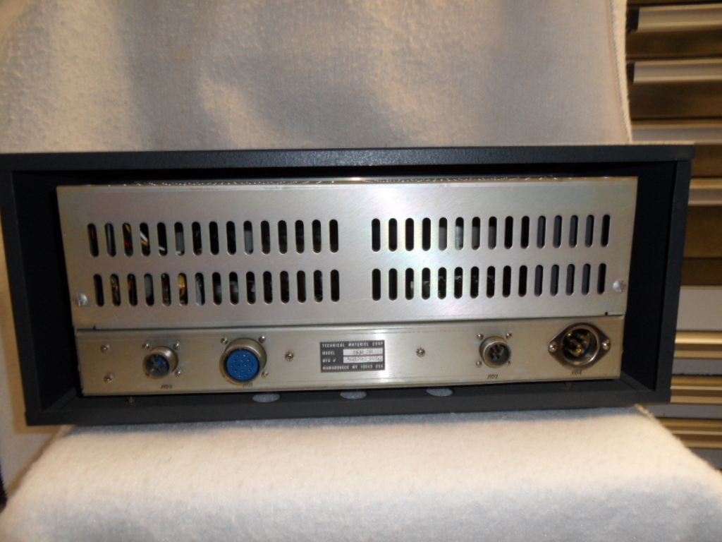
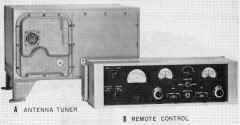
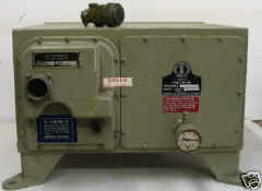
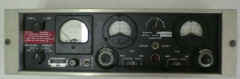
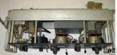
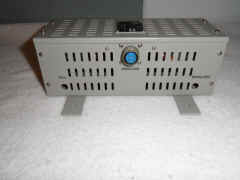
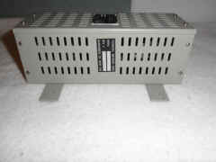
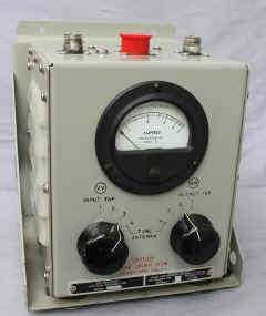
AN/URA-27
(50 ohm)
Antenna Coupler
AN/URA-34
(70 ohm)
Antenna Coupler
|
tuner photos thanks to WA5AVK |
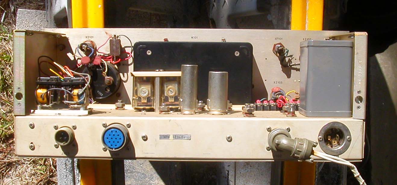
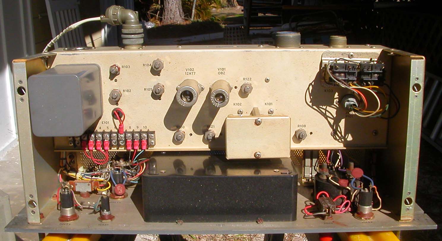
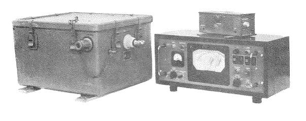
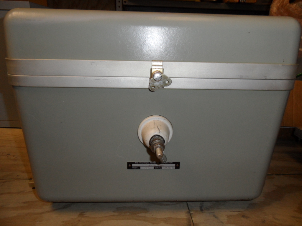
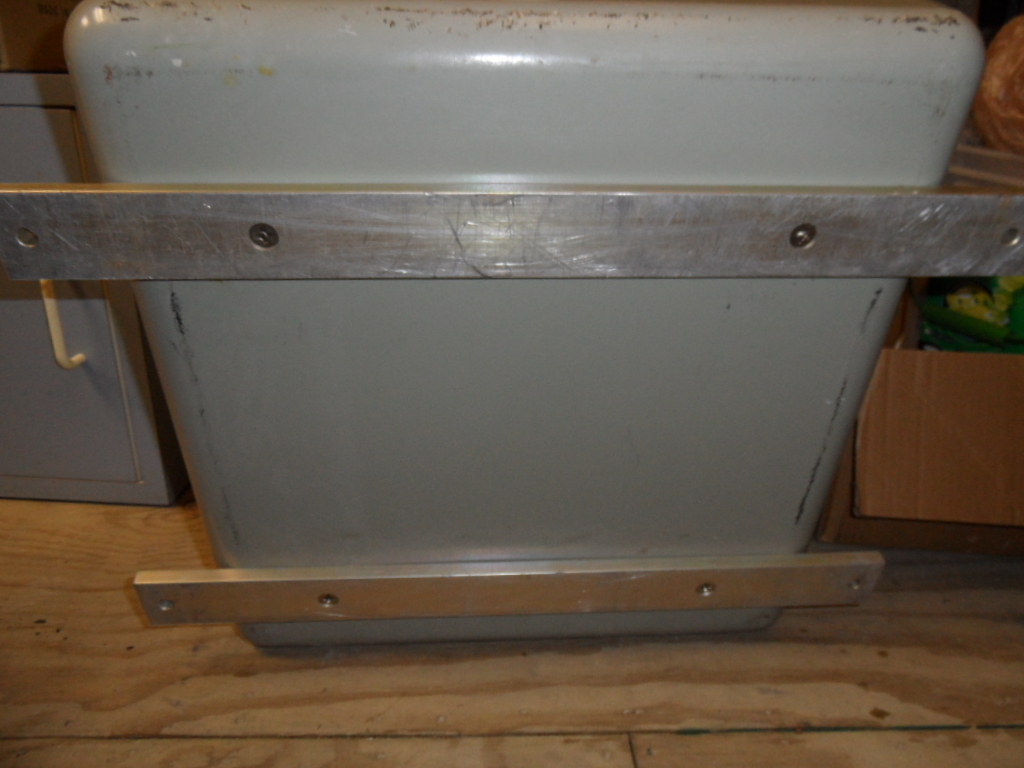
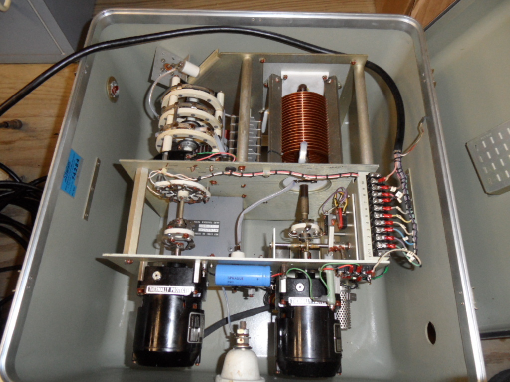
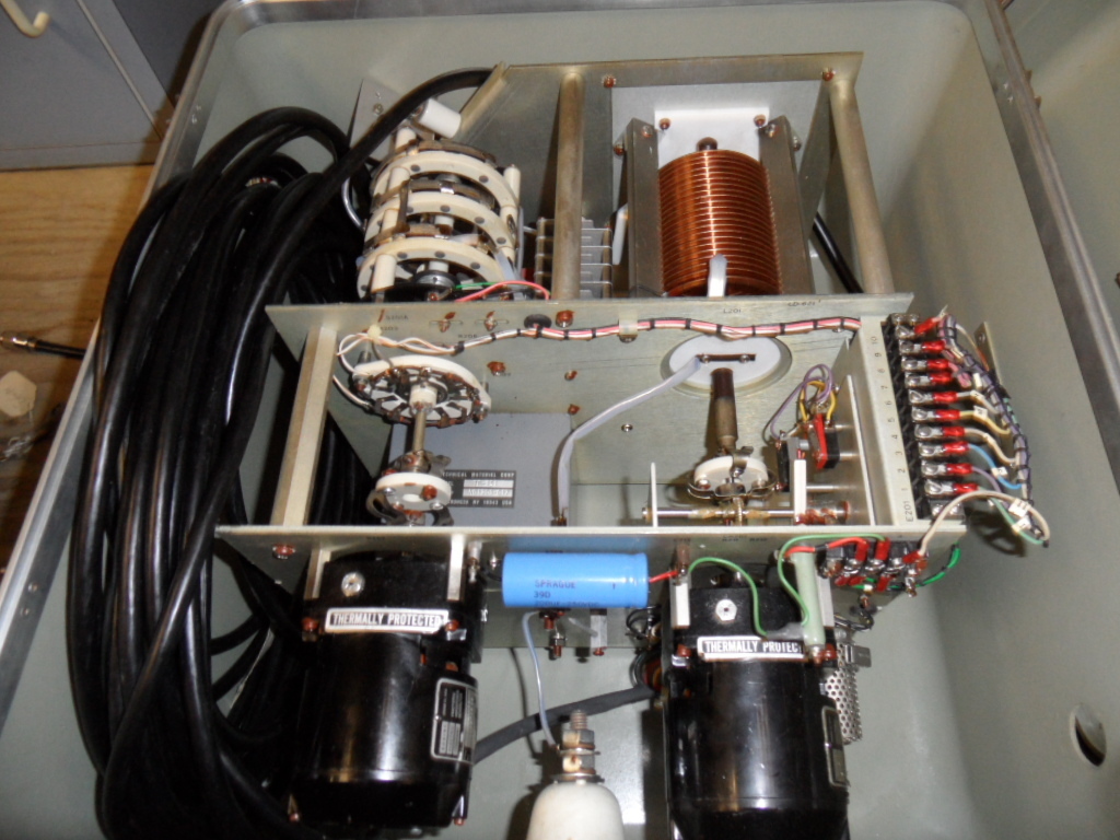
Antenna tuner 2-30mc, 1kw
CU-772/URA-27 tuner
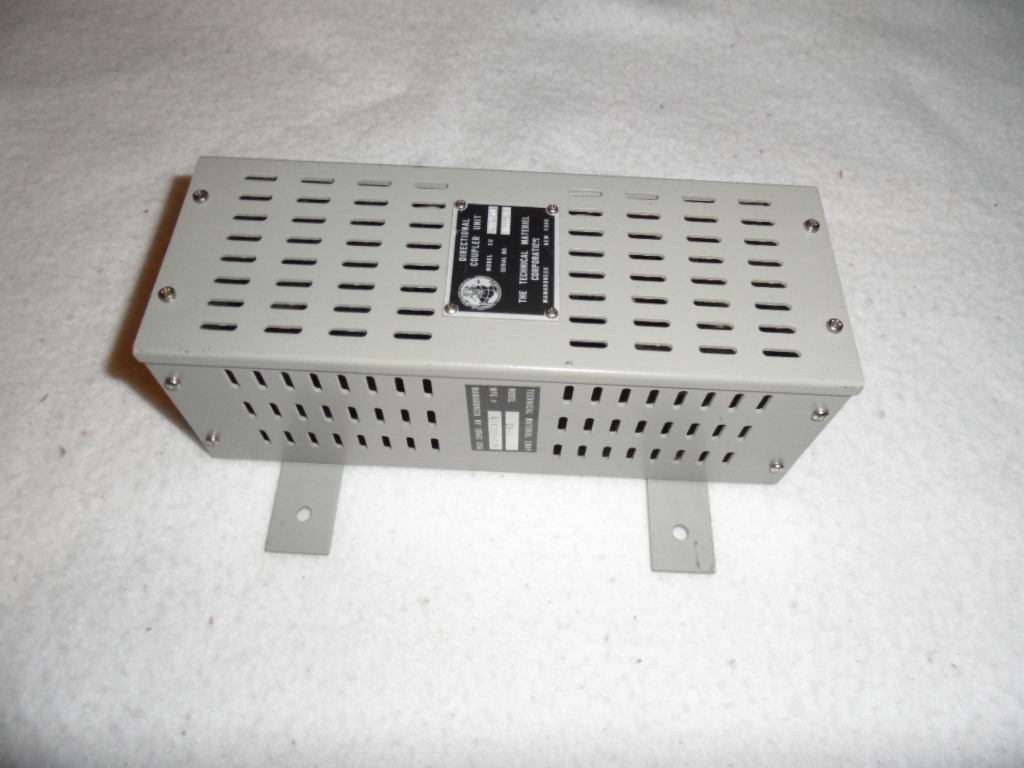
CU-773/URA-27 directional coupler
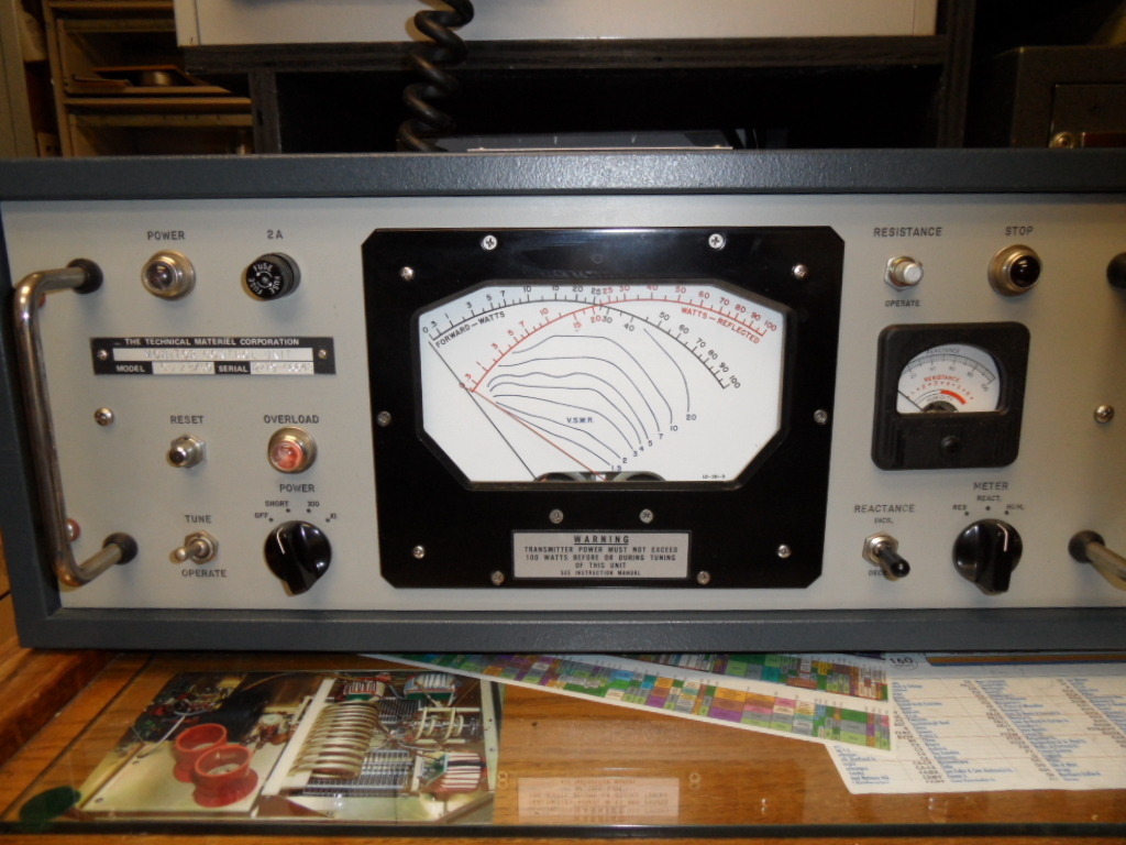
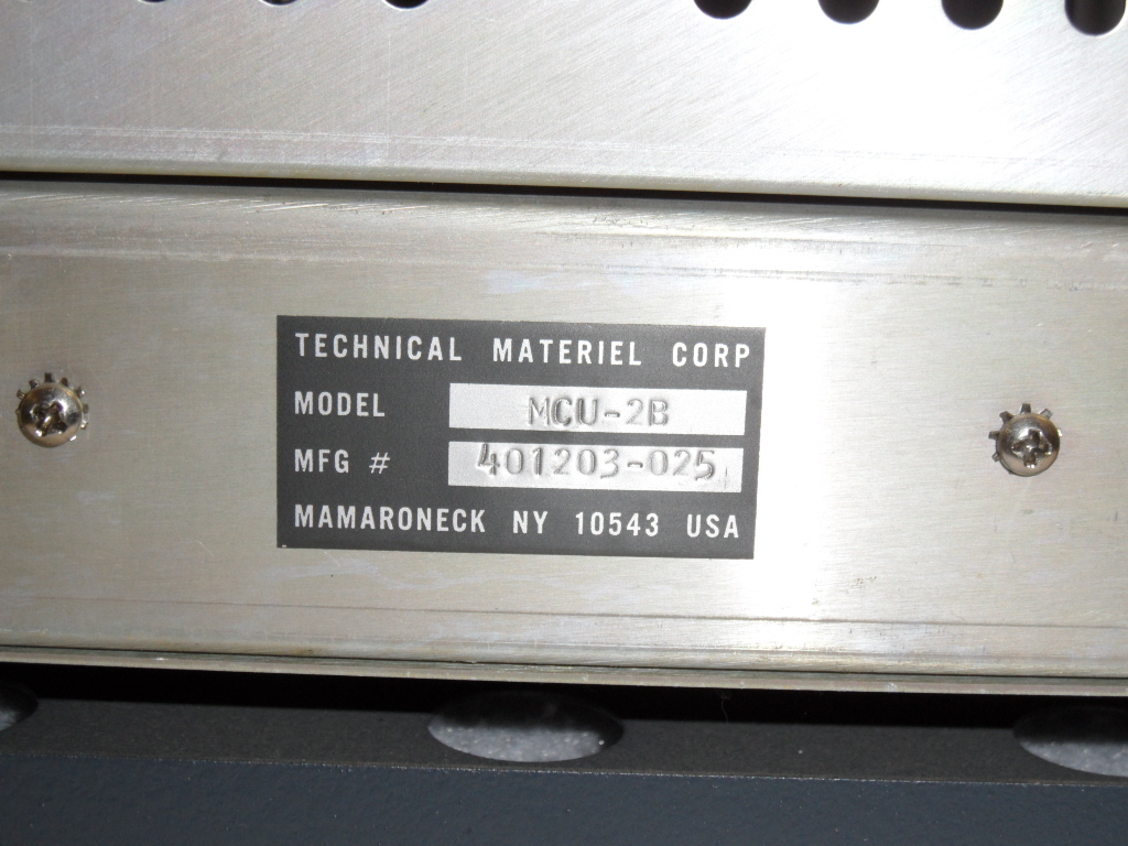
C-2995/URA-27 control monitor
|
manuf TMC model ATS-50-2 (50 ohm)
manuf TMC model ATS-70-2 (70 ohm)
manual
thanks to K4OZY
spec sheets
thanks to K4OZY

|

|
|
|
|
 |
|
 |
|
 |
|
 |
|
 |
|
 |
|
 |
|
 |
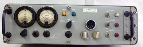
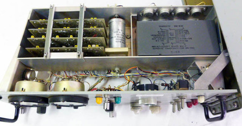
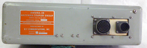
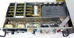
AN/URA-38
Antenna Coupler
HF coupler used with AN/URT-23
|
 |

|
 |
|
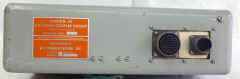
C-3698/URA-38 Control Unit
|
 |
|
 |
|
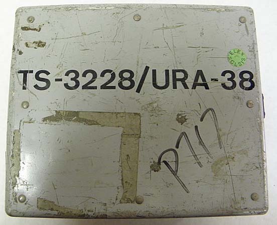
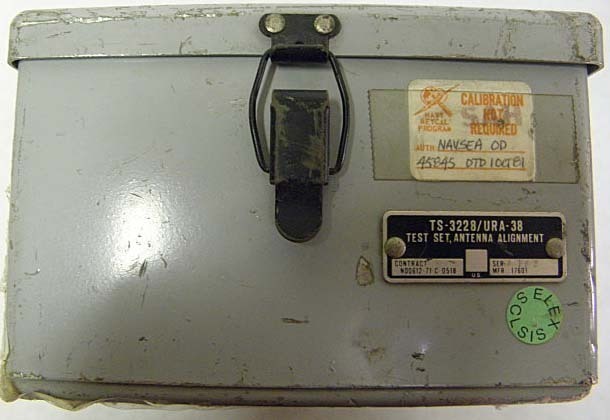
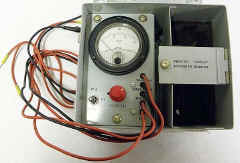
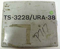
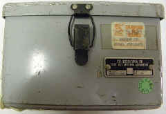
TS-3228/URA-38 Test Set
|
 |
|
 |
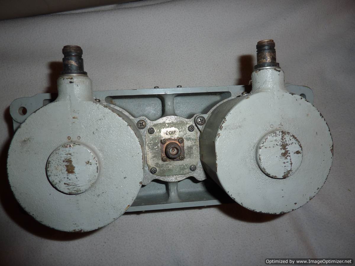
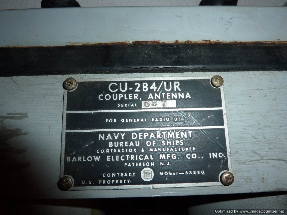
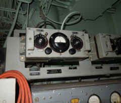
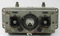
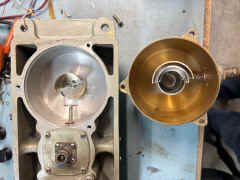
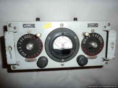
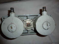
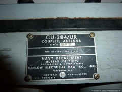
CU-284/UR UHF Multicoupler
Please let
me know if you have a manual I can scan
On board USS Kidd
|
 |
|
 |
K6YIC photo
 |
K6YIC photo
|
K6YIC photo
 |
|
|
 |
Front
|
Front
 |
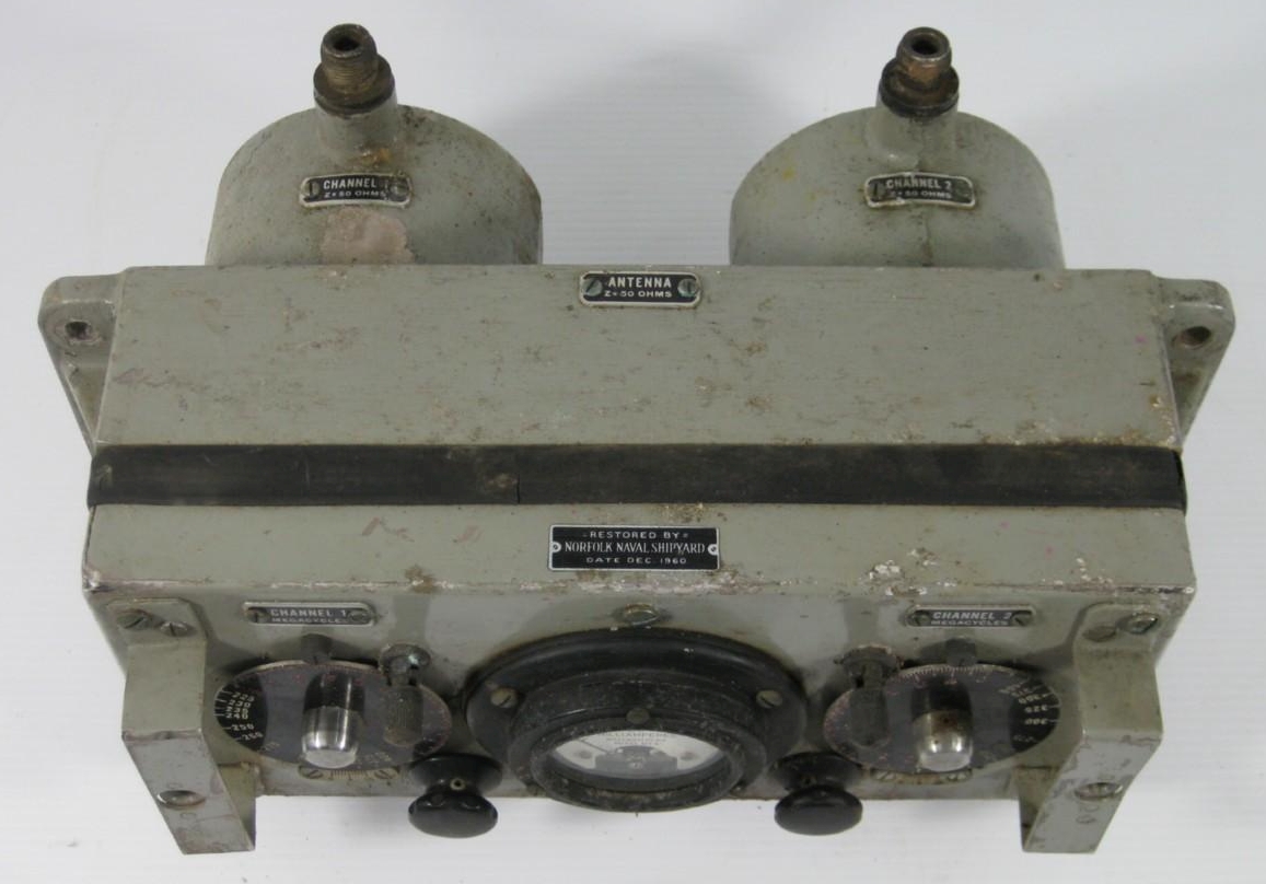
Rear

|
 |
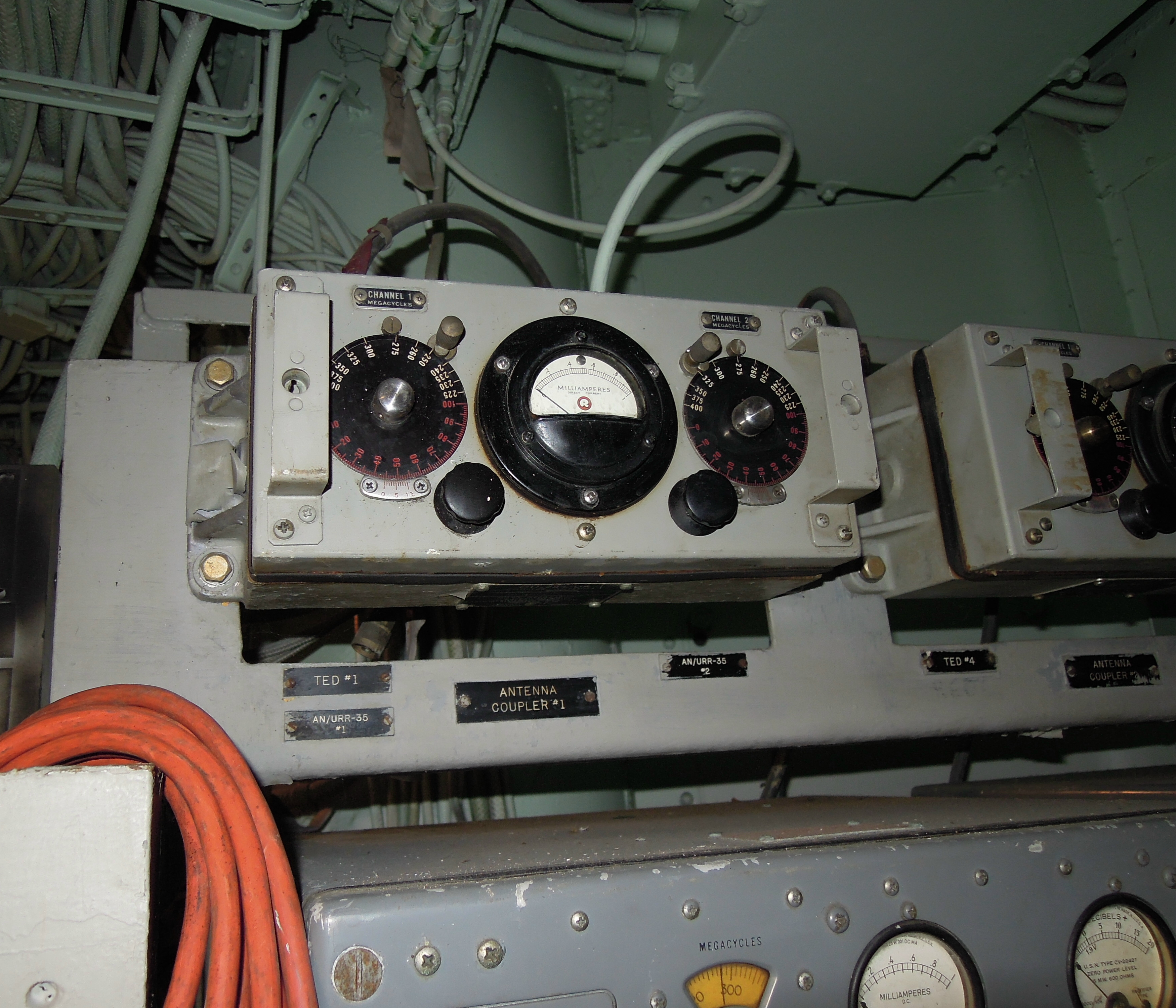
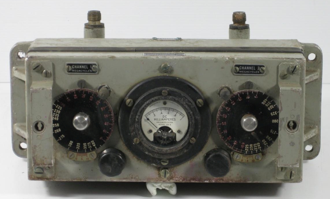
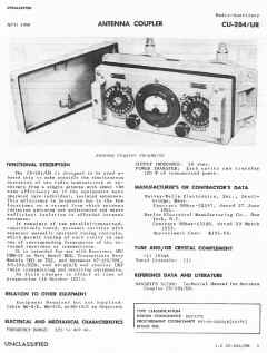
CU-284/UR permits the simultaneous operation of two UHF transmitters or receivers into a single antenna in the frequency range of 225 to 400 mc. It is designed for installation in submarines and other small vessels primarily.
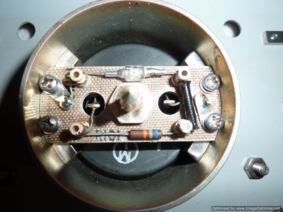
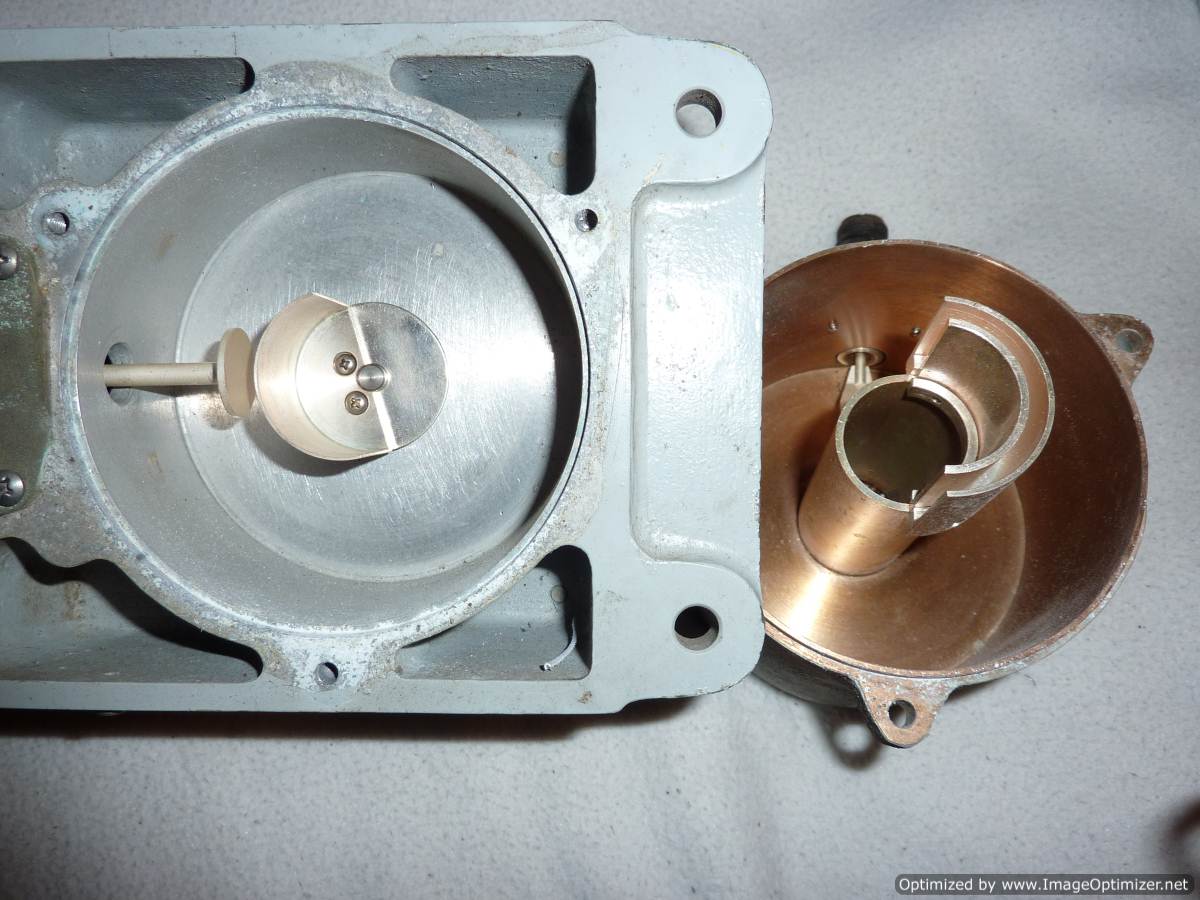
The coupler is tuned manually and consists of two capacitively-tuned resonant cavities; each cavity has a 50-ohm terminal impedance. The output circuit is provided with a metering circuit for indication of proper tuning of the cavities.
WEIGHT: 16 pounds
FREQUENCY RANGE: 225 to 400 mc
OUTPUT IMPEDANCE: 50 ohms
TYPE OF TUNING: Manual. tuning of capacitively-tuned cavities .
MAXIMUM R F INPUT POWER: 100 watts
INSTRUCTION BOOK: NAVSHIPS 91740
|
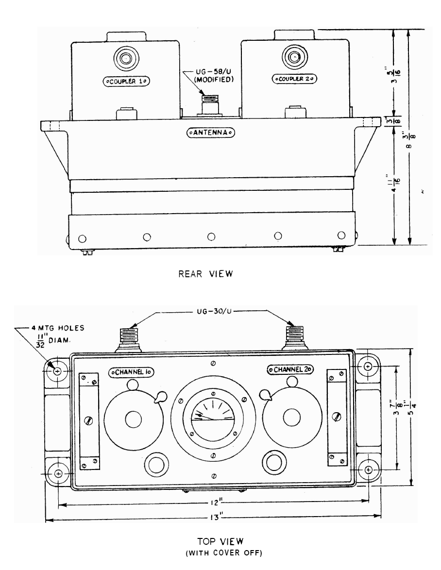
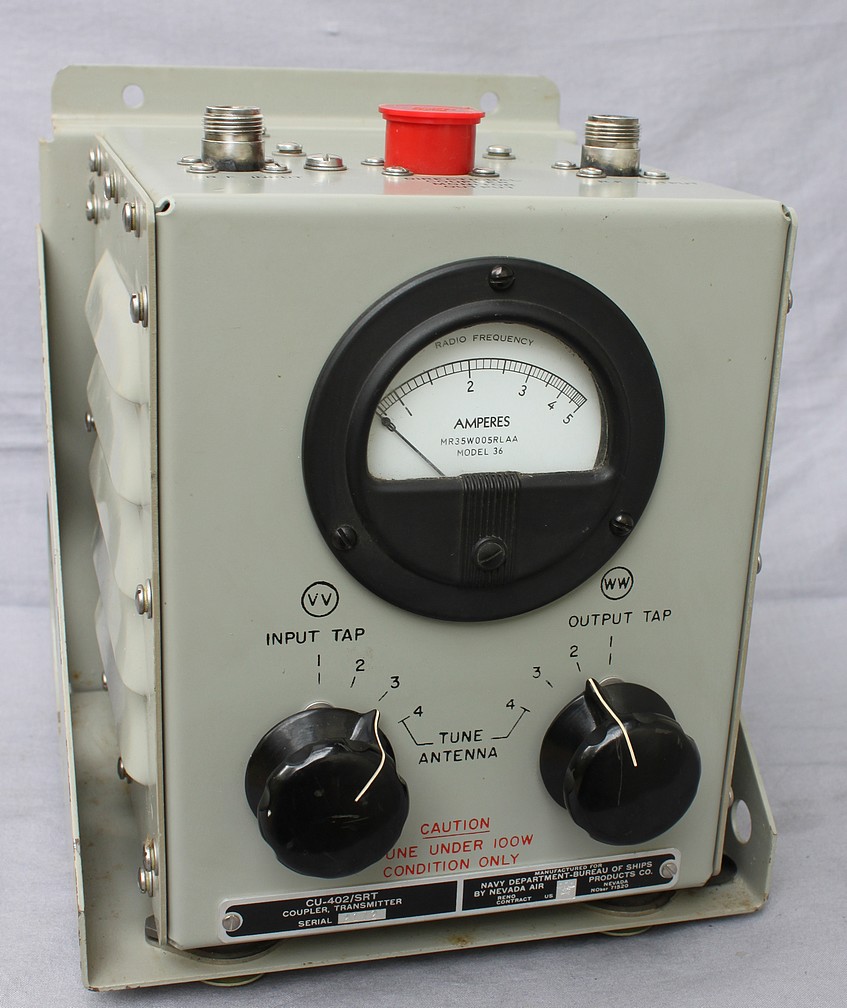
CU-402/SRT Transmitter Coupler
(for AN/SRA-18 tuner system and AN/SRT-14 series transmitters)
|
 |
|
 |
|
CU-402/SRT
is an antenna current meter plus impedance matching auto-transformer - it
was mounted below-decks near the transmitter and then low-loss coax ran
from it up on deck to a motor-driven variable inductor and remotely
switched capacitors which were used to tune the antenna (35' whip or
60-100' long wire). It is rated for 200w for 0.3-2.0 mc and 500w for
2.0-30.0 mc
The CU-402
would step-up or step-down the output impedance of the transmitter (which
varied with frequency) to match the 50 ohm coax load, but the extra L
& C units were needed to tune out the reactance of the antenna.
The CU-402
also has a directional coupler that ran back to a metering circuit
located in the SRT-14 transmitter (via the 3-pin connector).
|
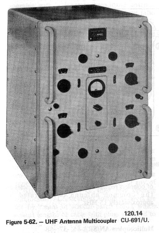
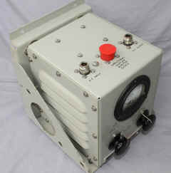
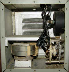
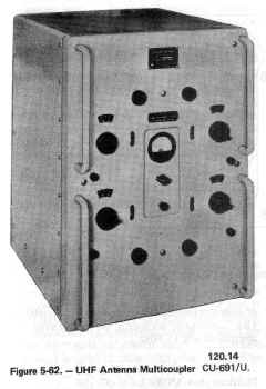
CU-691/U & CU-692/U
UHF multicouplers
|
225-400mc

|
CU-691/U handles four sets
CU-692/U handles two sets
|
|
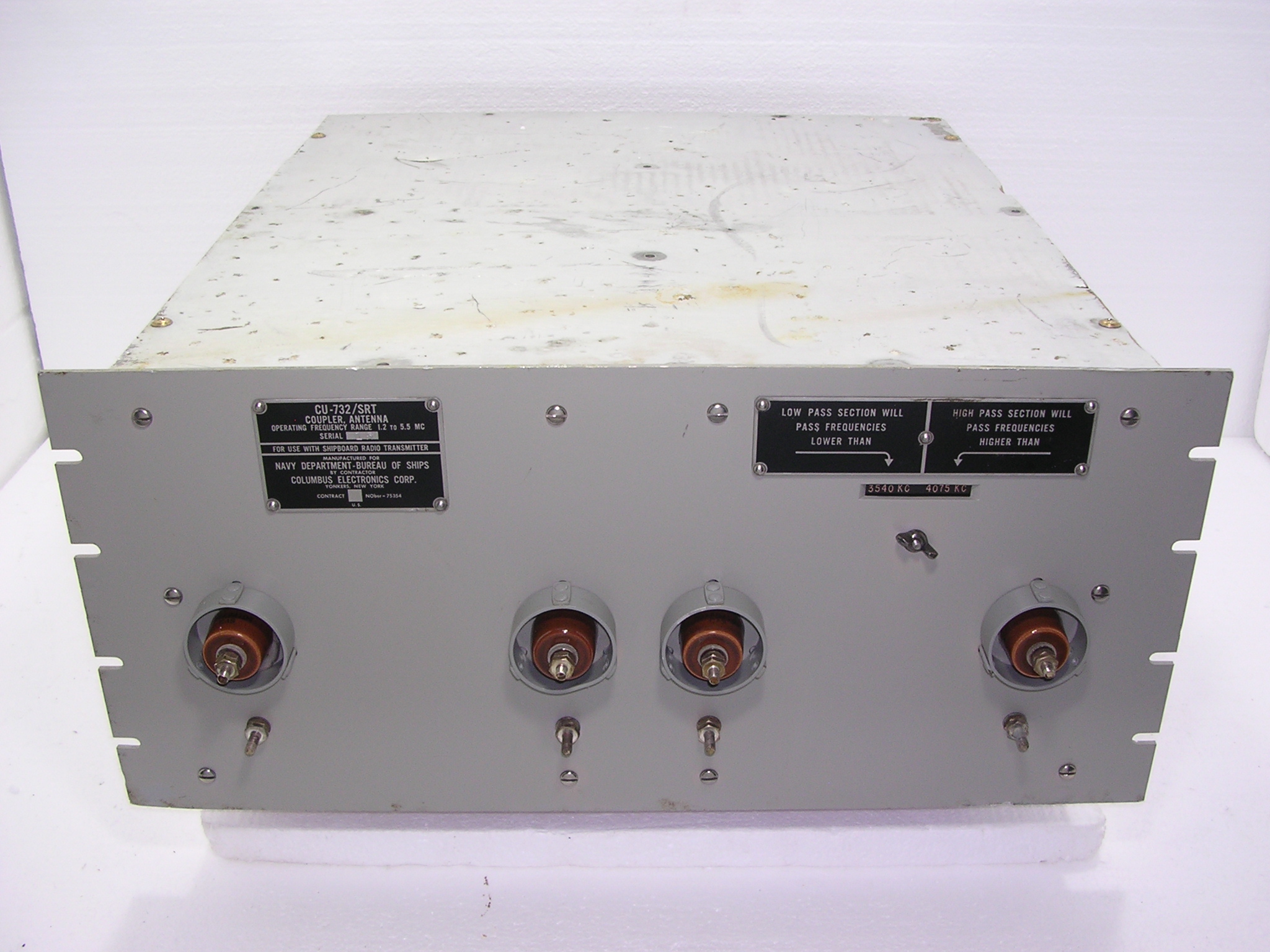
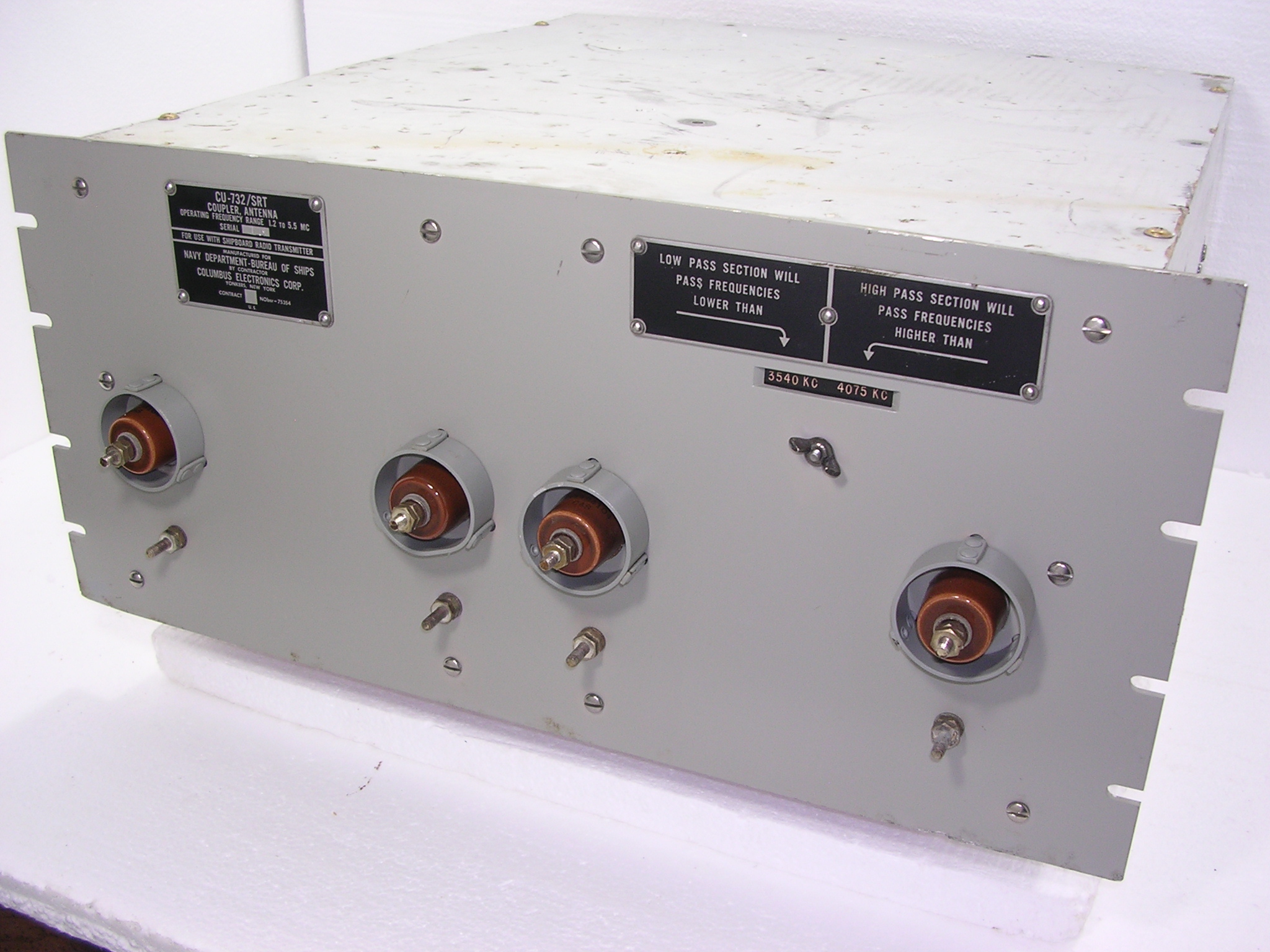
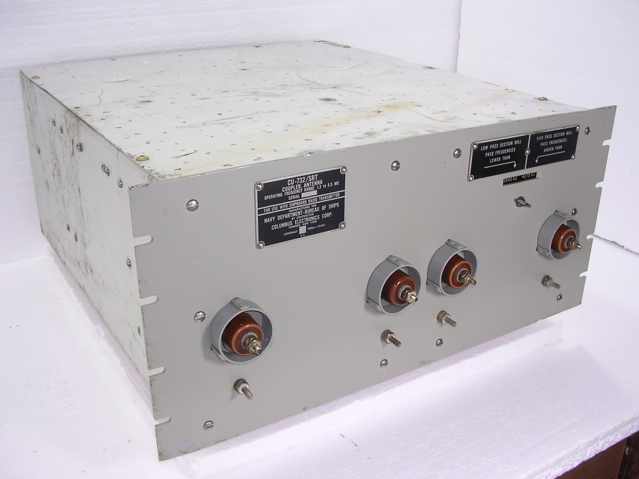
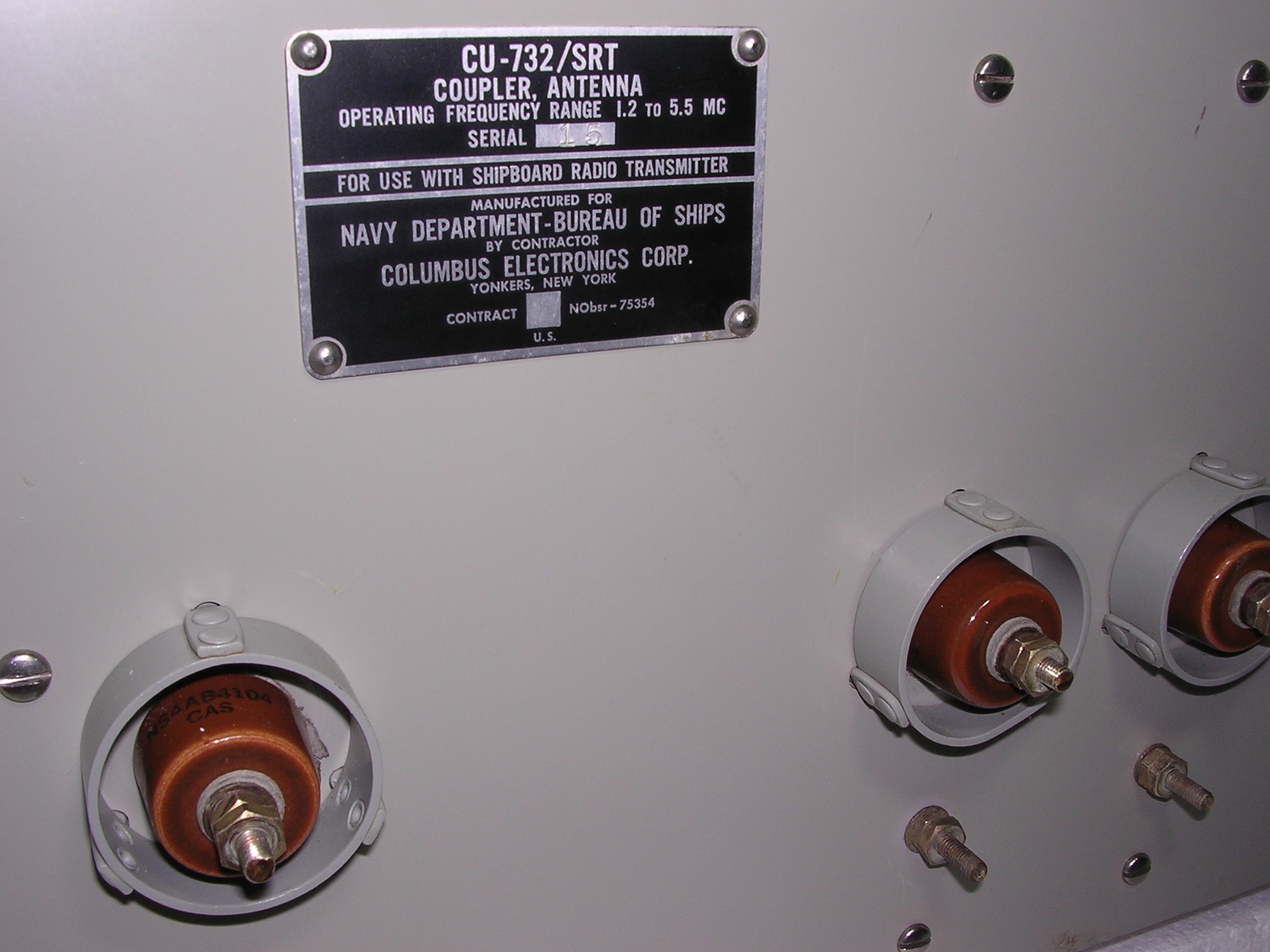
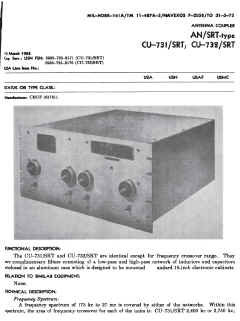
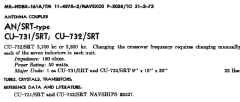
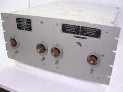
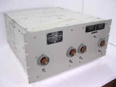
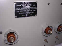
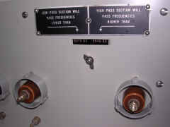
CU-731/SRT & CU-732/SRT
Bandpass filters
|
See F-156/SRT series below
|
|
|
 |
|
|
|
 |
|
|

|
 |
|
|
|
 |
|
|
|
 |
|

|
|
 |
|
|
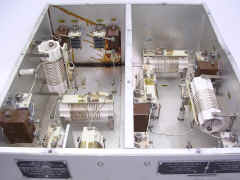
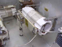
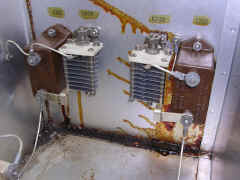
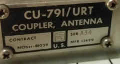
CU-791/URT Coupler
(Collins 180Y-1)
|
 |
Download manual
|
--
|
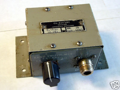
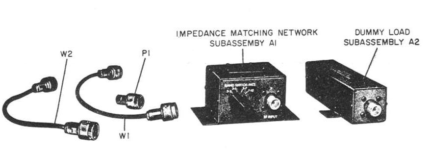
CU-837/URC
Matching Network
|
 |
network matching switch
50 ohm output for TCS
(use with AN/SRA-22 coupler)
2-3 mc
3-5 mc
5-7 mc
7-12 mc
|

|
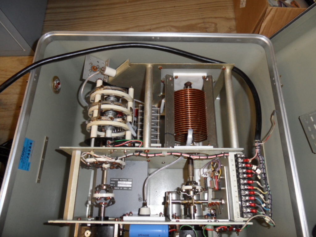
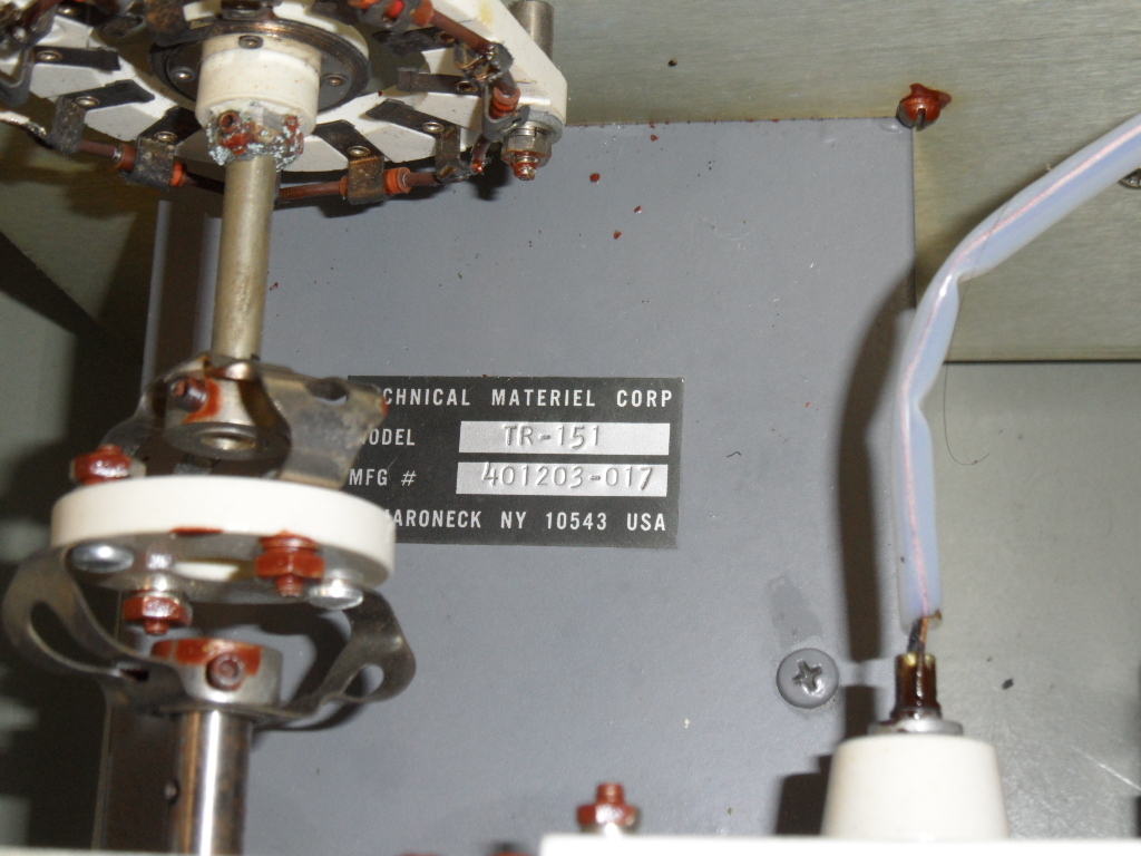
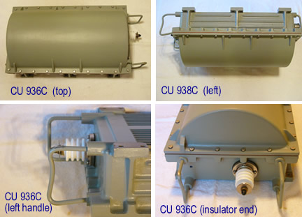
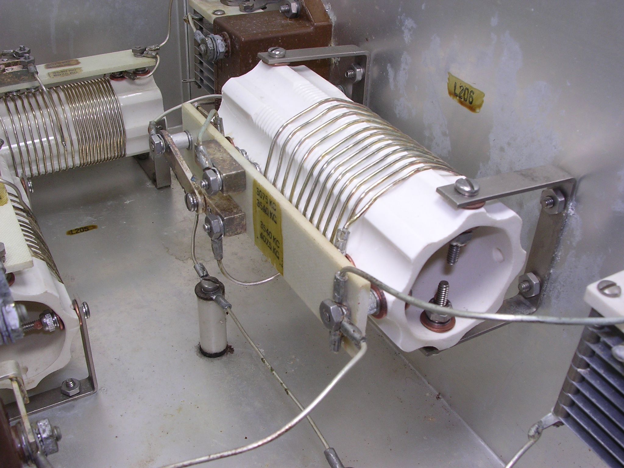
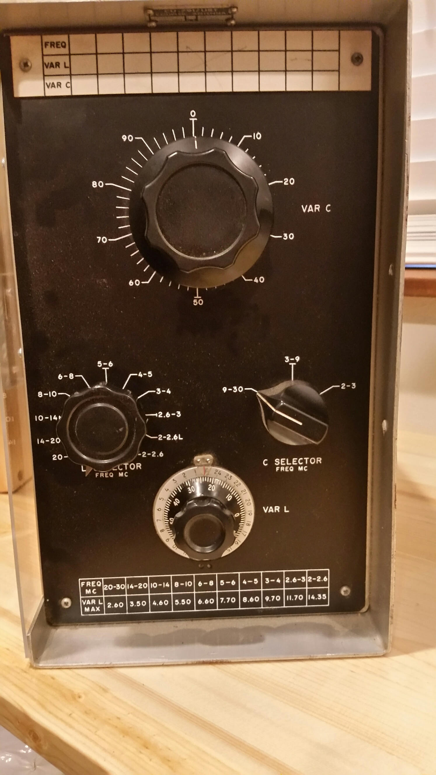
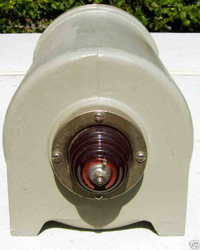
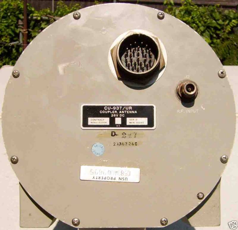
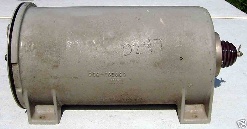
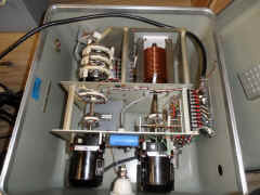
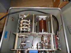
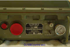
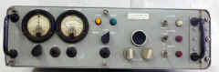
CU-937/UR
Antenna Tuner
|
 |
|
More photos |
CU-1169/SRC-16
(part of AN/SRA-34)
|
Download CU-1169 manual |
AN/SRA-34 information
|
-- |

|
 |

|
 |

|
 |

|
 |

|
 |

|
 |
CU-1170/SRC-16
|
-- |
--
|
-- |

|
 |

|
 |

|
 |

|
 |

|
 |
==
|
== |
CU-2184/URC-94
|
 |
|
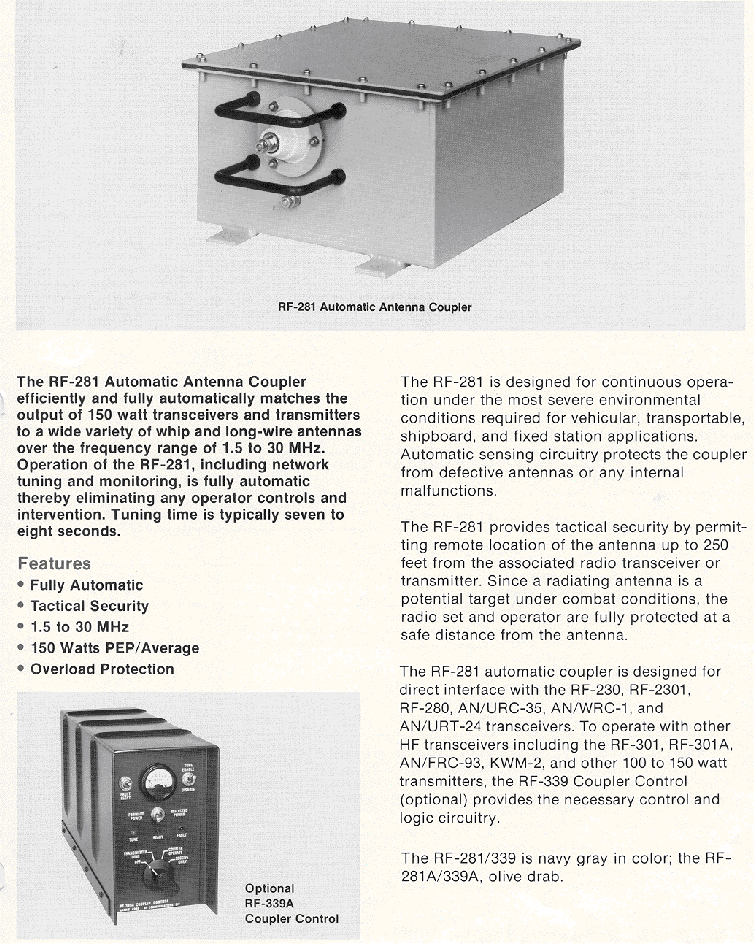
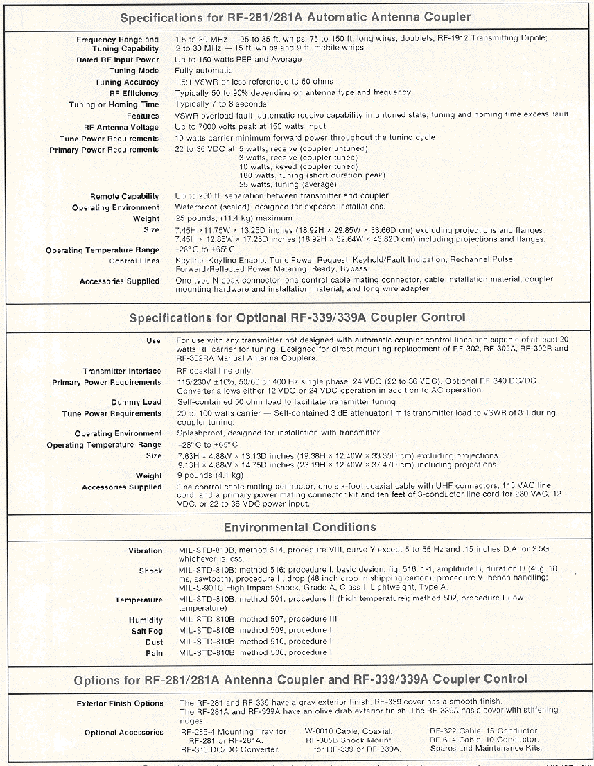
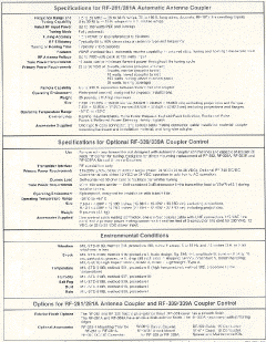
Harris RF-281
Used with URC-35, WRC-1, etc.
Manual download |
F-156/SRT
F-157/SRT
F-158/SRT
F-159/SRT
F-160/SRT
F-161/SRT
F-162/SRT
F-163/SRT
Transmitting Filters
|
 |
|
 |
|
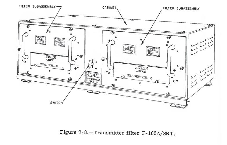
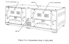
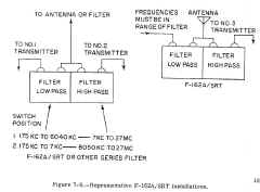
Transmitting Filter Assemblies - The filters that will now
be described have been designed for use with shipboard transmitters and
antennas that are unbalanced to ground. This series includes Electrical
Filter Assemblies F-159/SRT, F-160/SRT, F-161/SRT, F-162/SRT, and F-163/SRT.
A representative filter assembly of this series, the F-162A/SRT, is shown
in figure7-8.
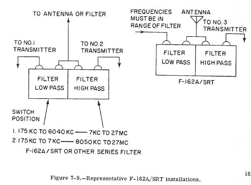
Each filter assembly consists of low-pass and high-pass
subassemblies. They are used with transmitters operating in the frequency
range between 175 kc and 27 mc. Single filter assemblies (fig. 7-9) can be
used alone or combined with other subassemblies to operate two or more
transmitters (using different frequencies) into a single antenna.
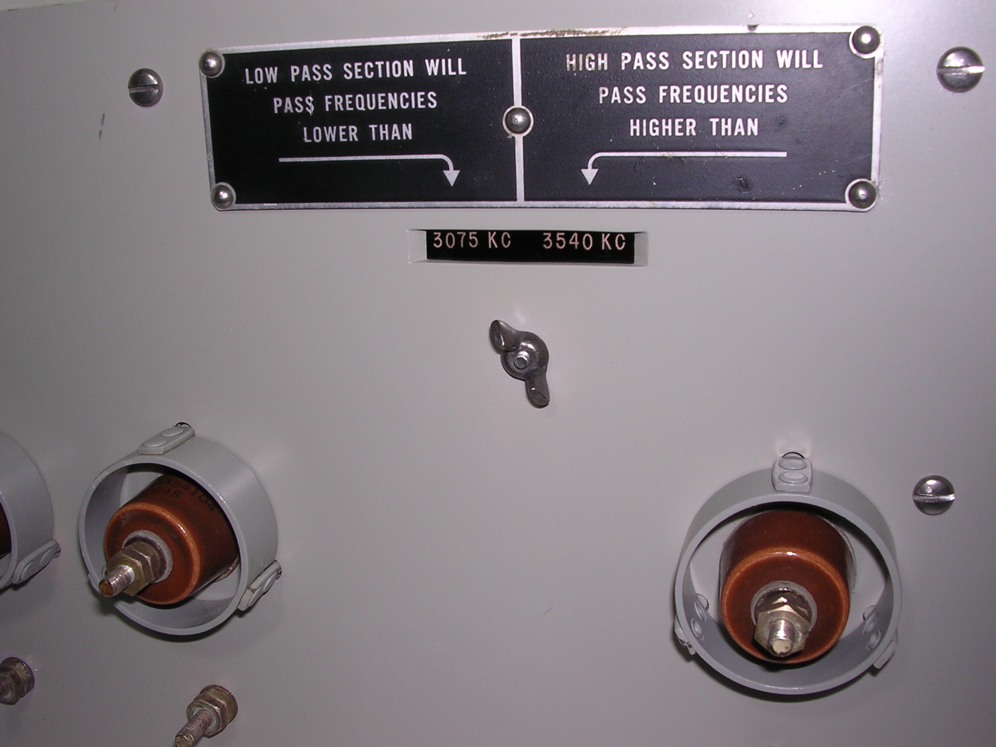
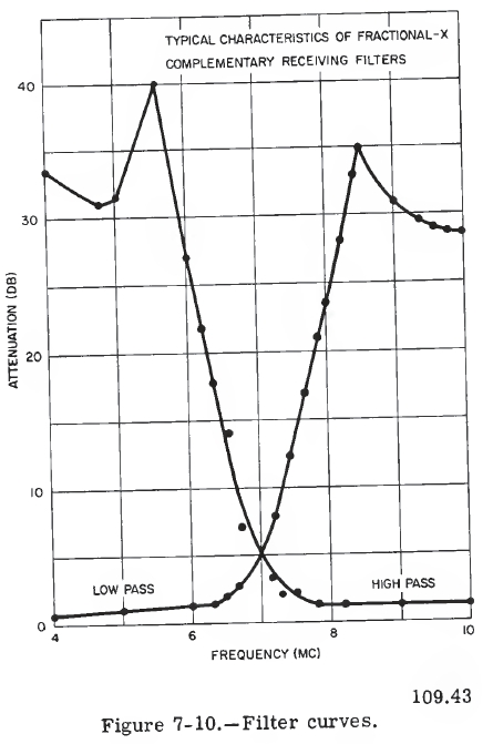
Because a low-pass filter and a high-pass filter are used
in each filter assembly, there is a definite crossover frequency for each
filter. In the vicinity of the crossover frequency there is a band of
frequencies, called the precluded band, which cannot be used because
appreciable power would be lost in the filter. When frequencies in the
vicinity of the crossover frequency are to be used, it is necessary to
change the crossover point. By removing the crossover point around as the
precluded band is approached, it is possible to obtain continuous coverage
of the 175-kc to 27-mc frequency range, A switch in the center of the
front panel on all assemblies except the F-160/SRT, permits shifting of
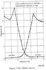
the crossover frequency. Figure 7-10 shows curves for both low-pass and
high-pass filters for the F-162A/SRT.
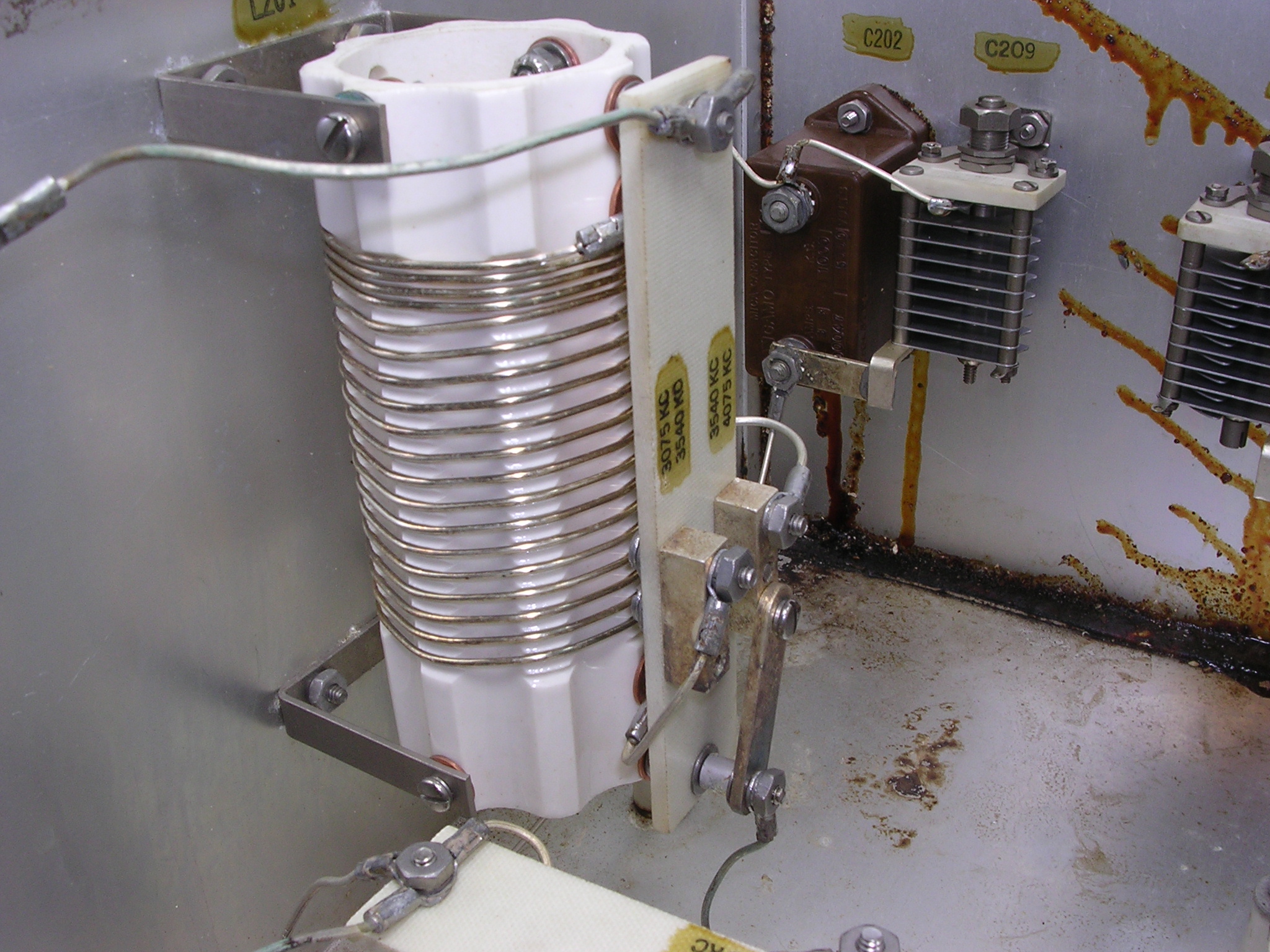
The filter assemblies are constructed in the form of
plug-in drawers. Normally, the lowpass drawer is installed on the left
side of the cabinet and the high-pass drawer on the right side, as viewed
from the front, however it is possible to interchange the subassemblies
from left to right in the cabinet by changing a connecting strap in each
subassembly.
In normal operation, the filter assemblies dissipate less
then 20 percent of the r-f power output of the transmitter. Because it is
possible for a fault, such as a grounded antenna, to develop, each filter
subassembly is designed to dissipate over 500 watts, if necessary.
Because the low-pass filter section provides a termination
for the high-pass section and vice versa, it is not advisable to operate a
transmitter into one section alone. If it becomes necessary to operate a
transmitter when either filter section is removed, a jumper assembly
furnished with each cabinet is used to connect the transmitter directly to
the antenna. Other transmitting filter assemblies presently in use include
the F-156, -157, and -l58/URT.
|
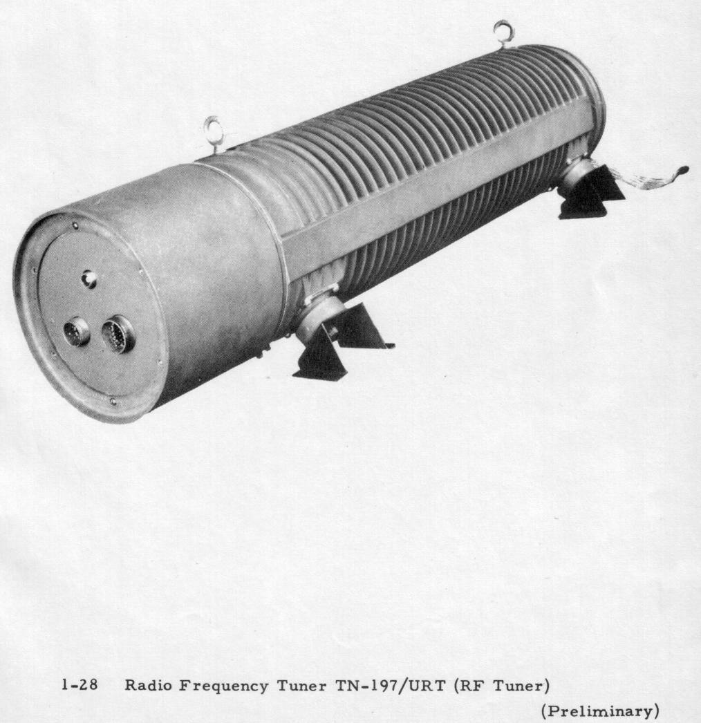
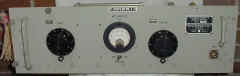
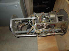
TN-197/URT
antenna tuner for URT-2 series transmitters
System components:
OA-297/URT controller group
CB-5/URT capacitor tuning unit
TN-197/URT inductor tuning unit
|
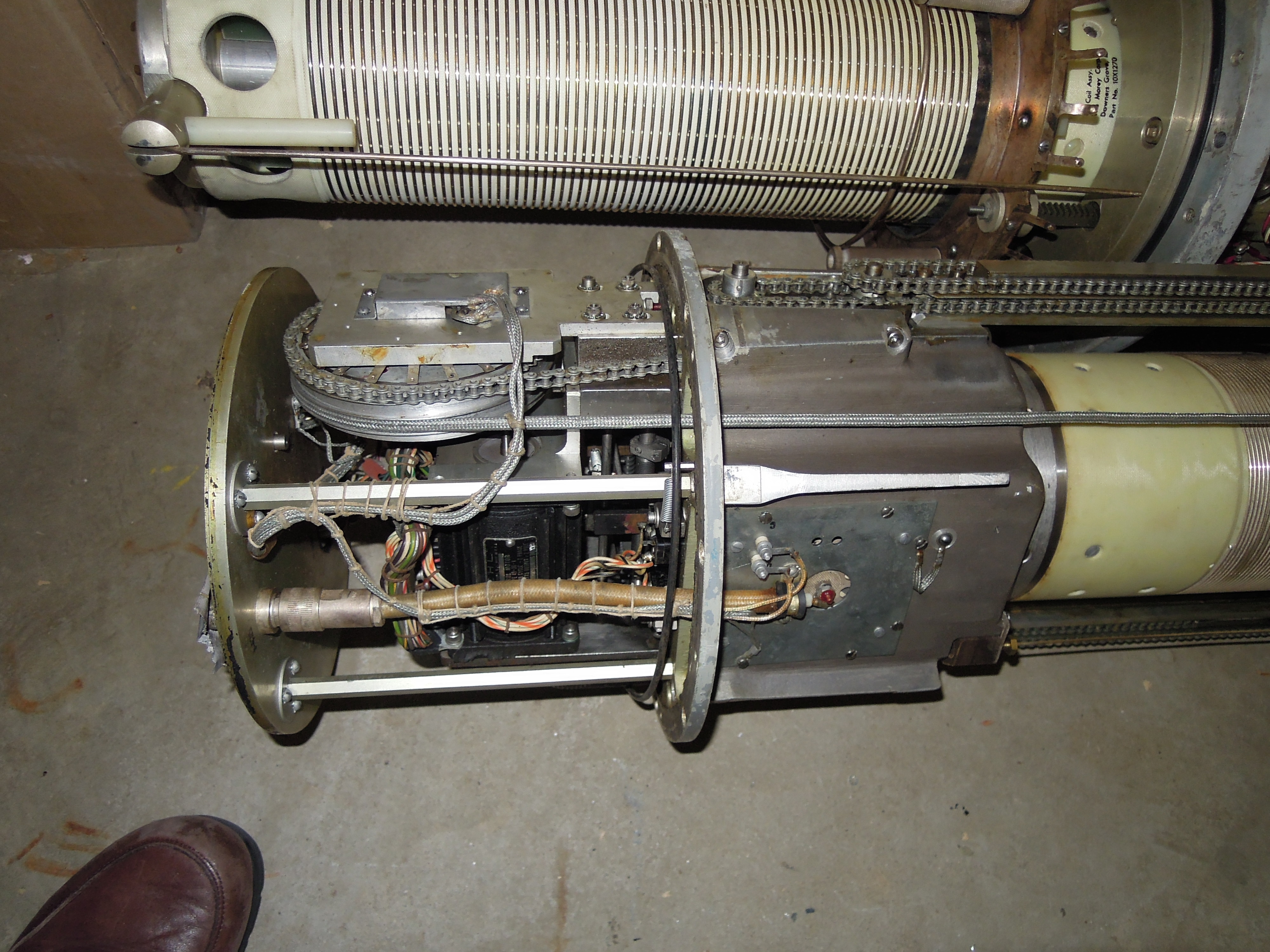
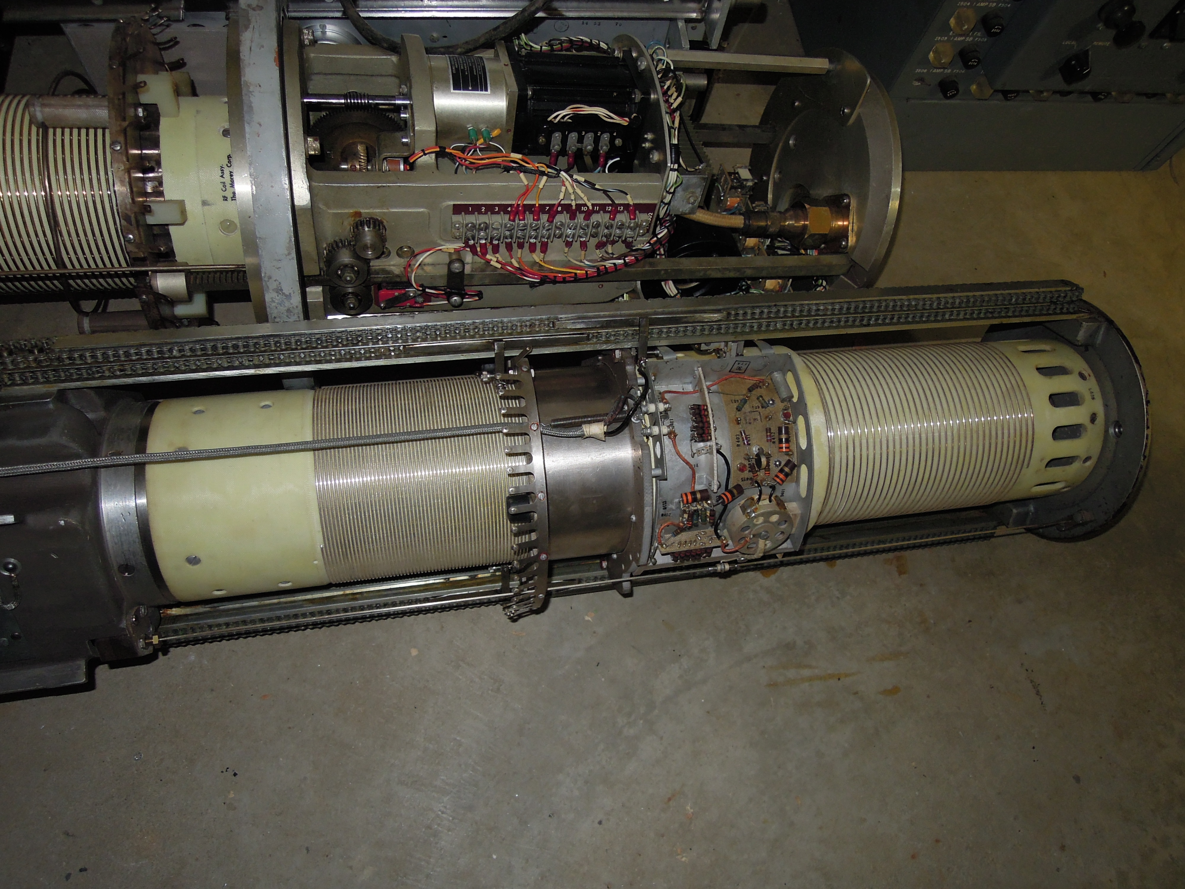
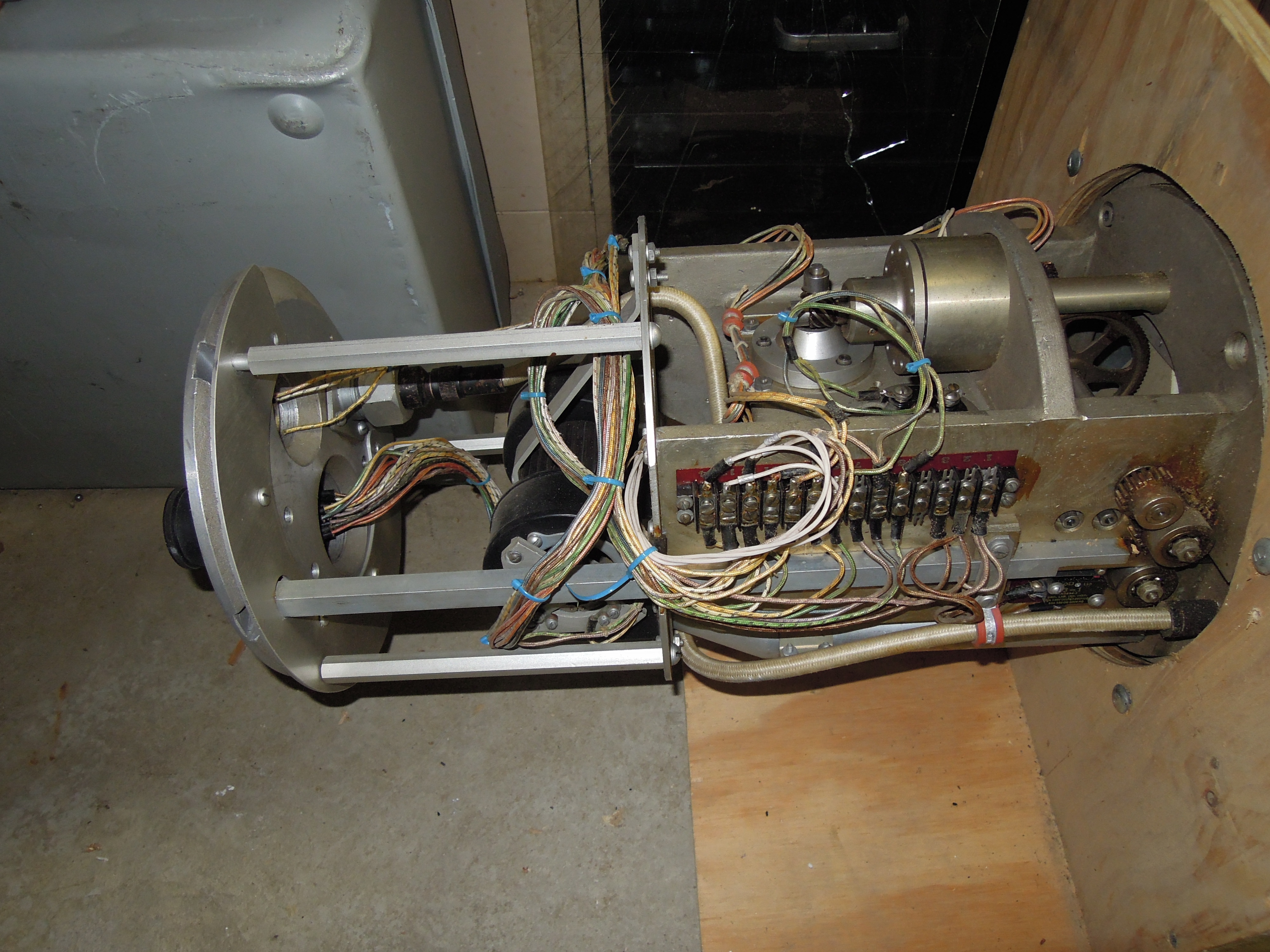
TN-197/URT inductor tuning unit |
motor/control end
|
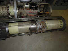
tuning coil end |
TN-229/SRT
antenna tuner for SRA-18 system and SRT-14 series transmitters
System components
TN-229/SRT antenna tuner
CU-372/SRT antenna coupler
CU-402/SRT load adjusting unit
|
need photo of assembled unit - similar to TN-342
below |
motor/control end
|
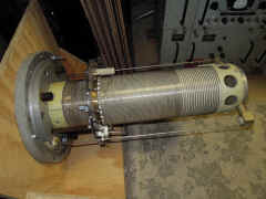
tuning coil end |
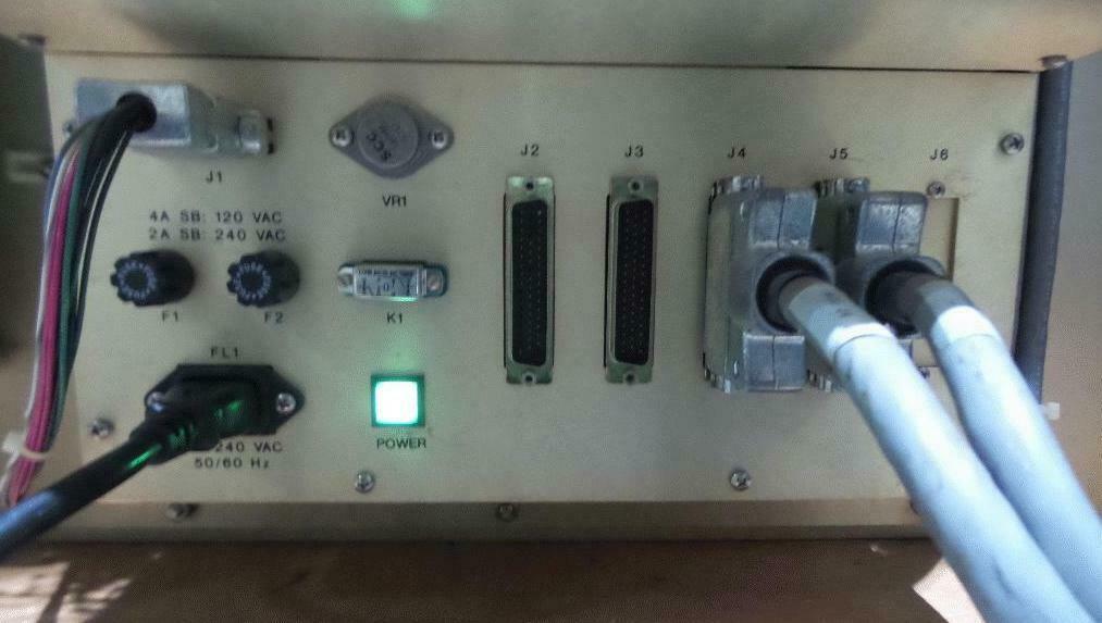
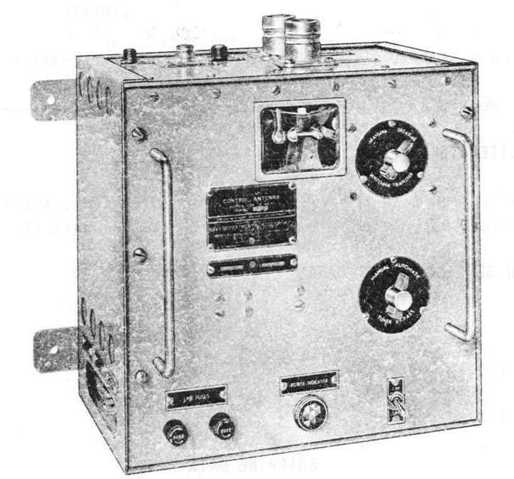
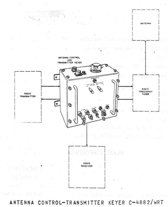
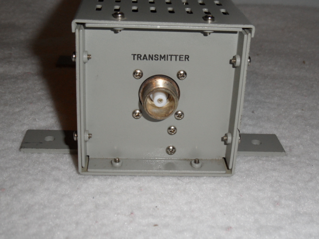
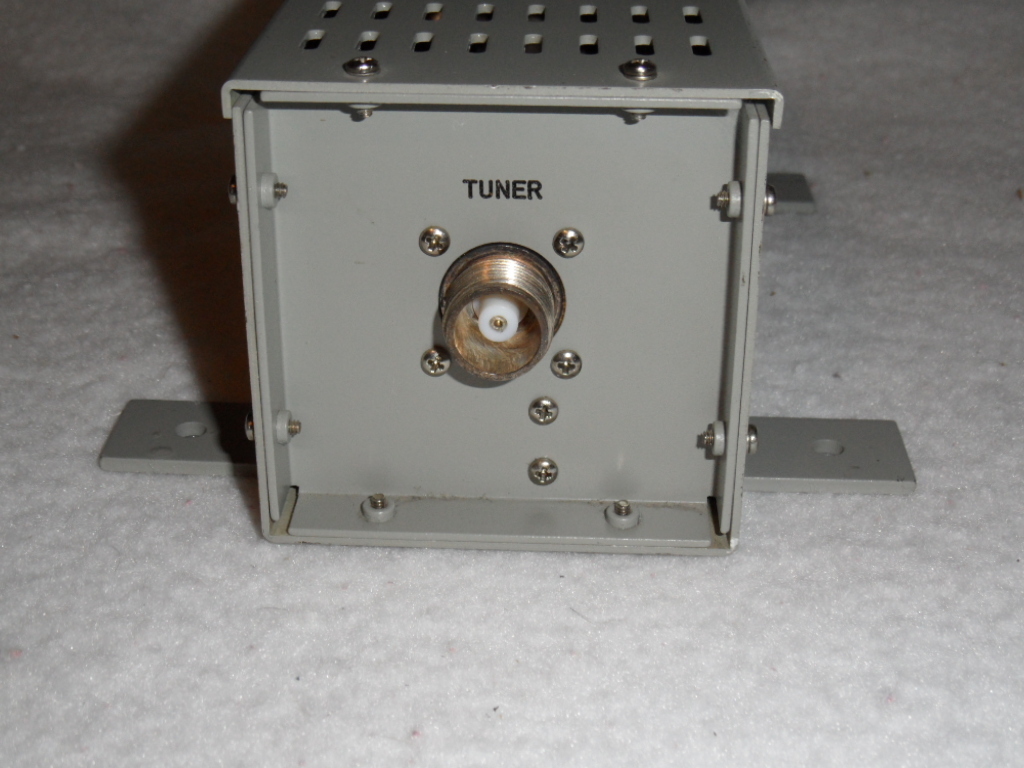
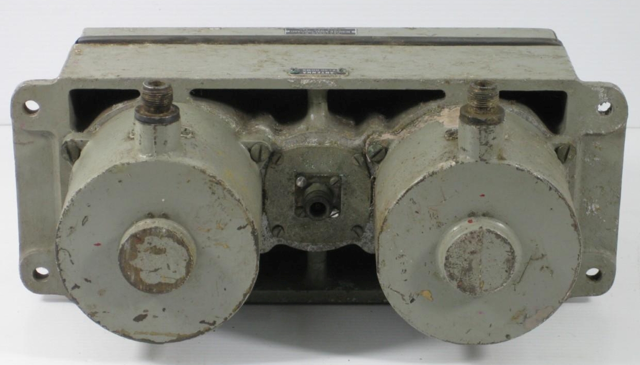
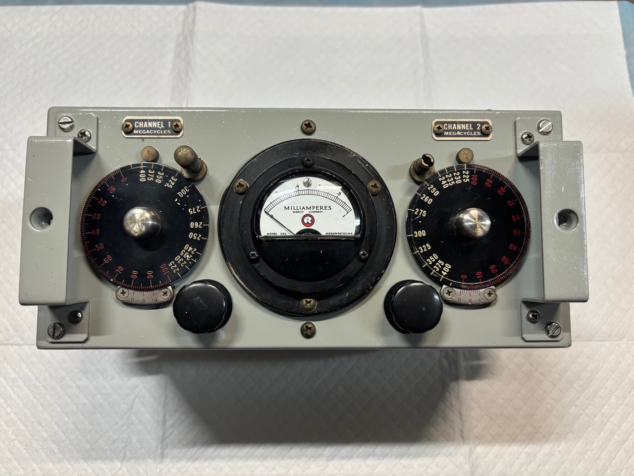
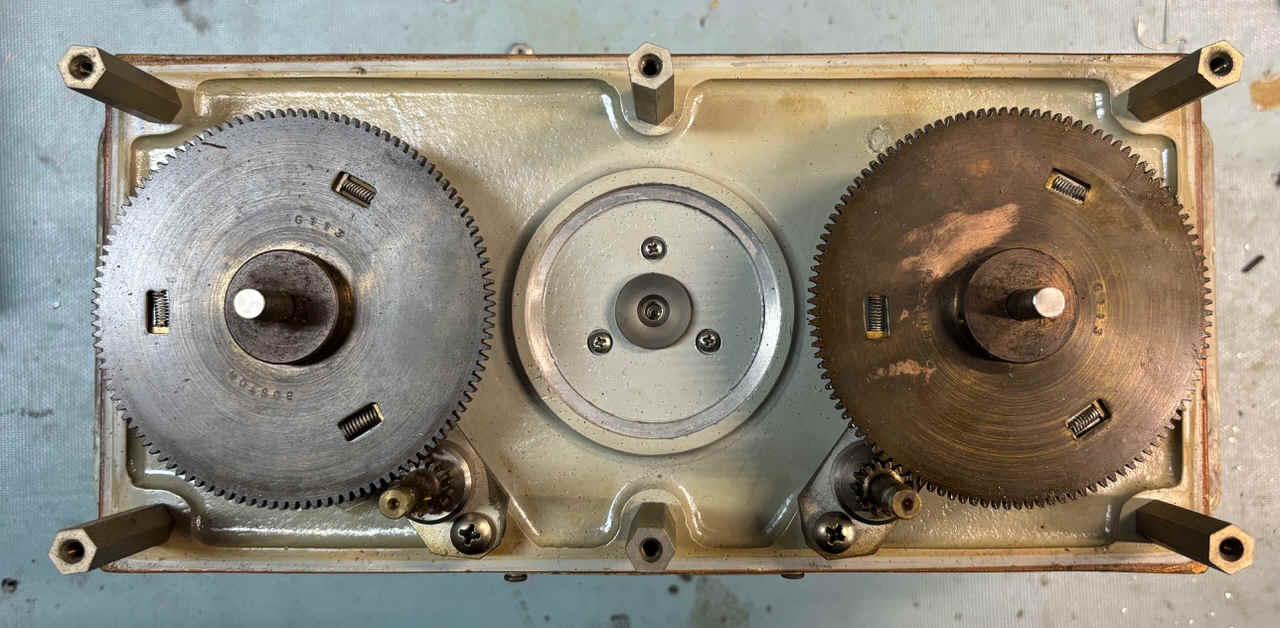
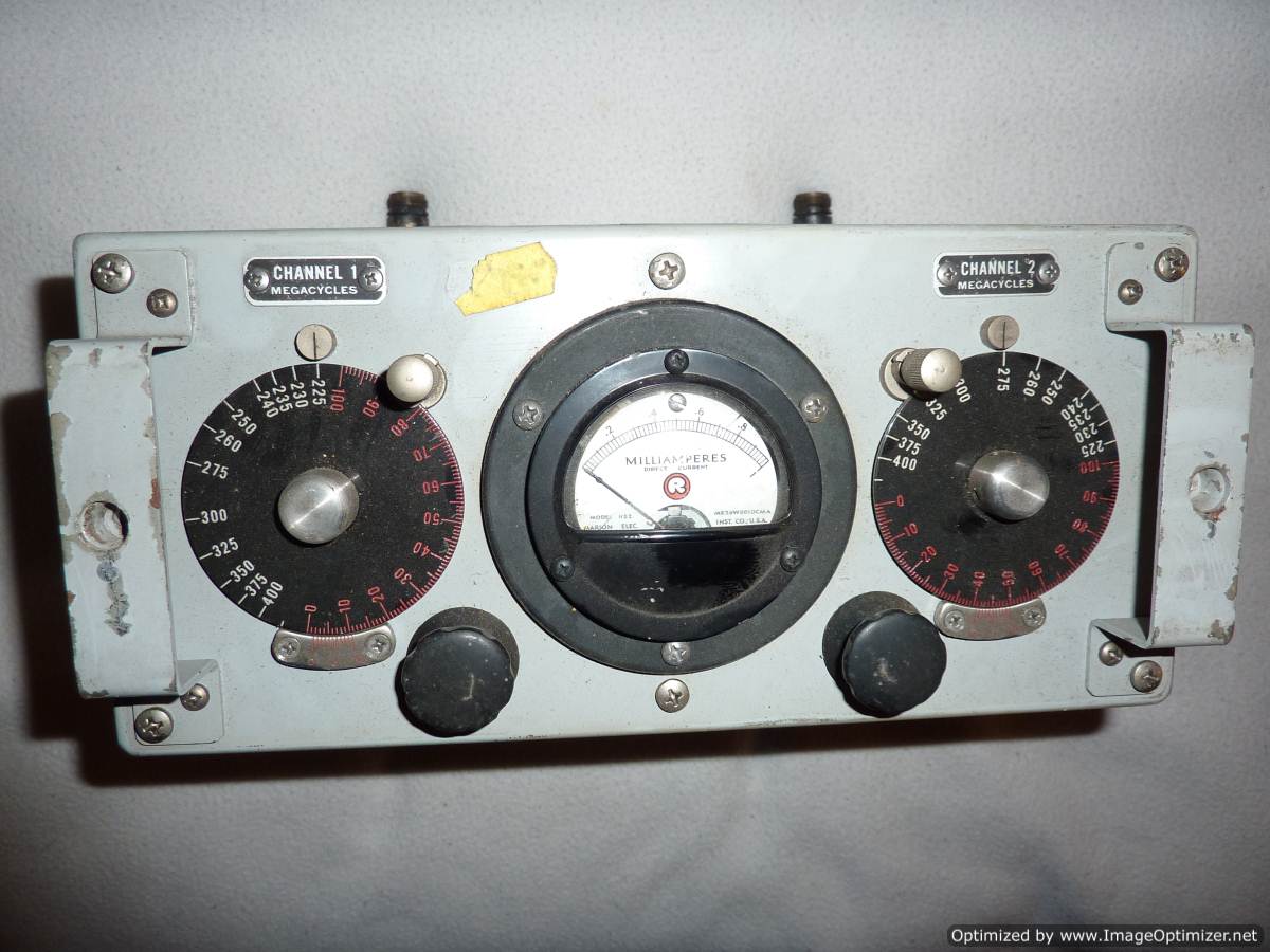
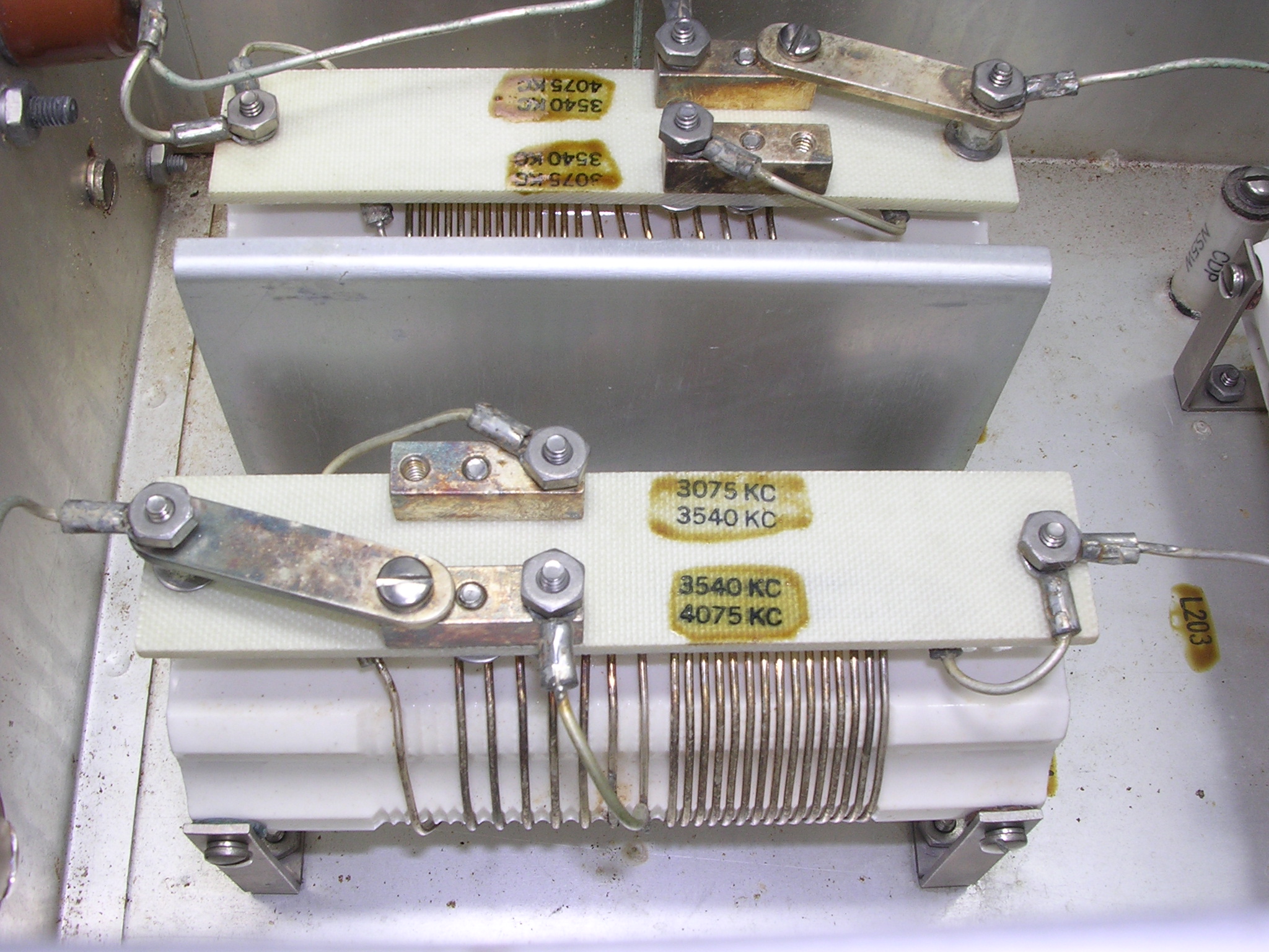
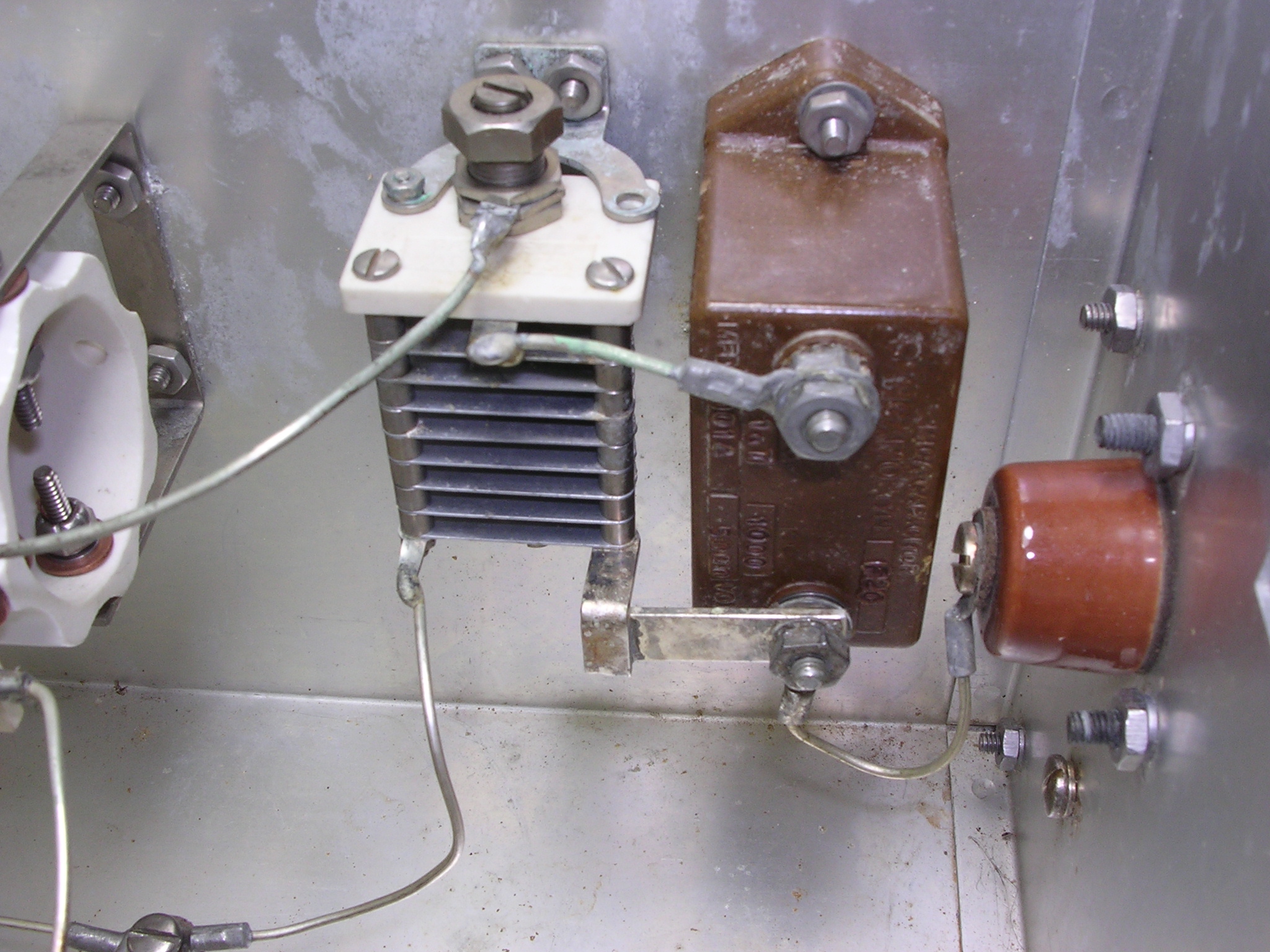
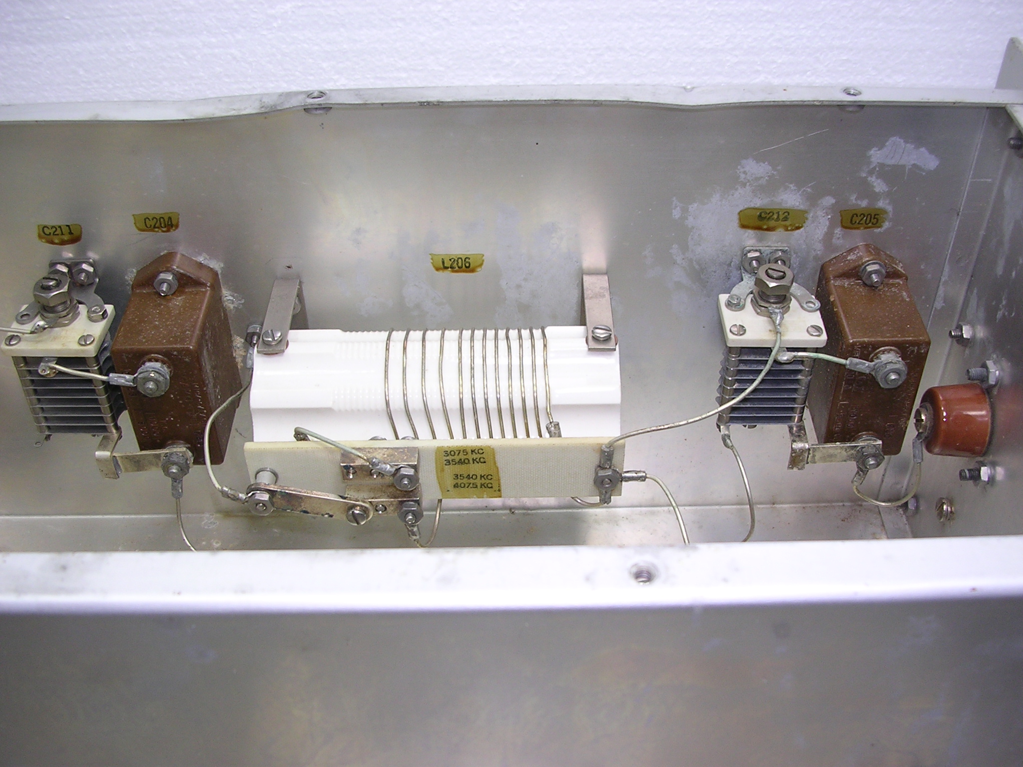
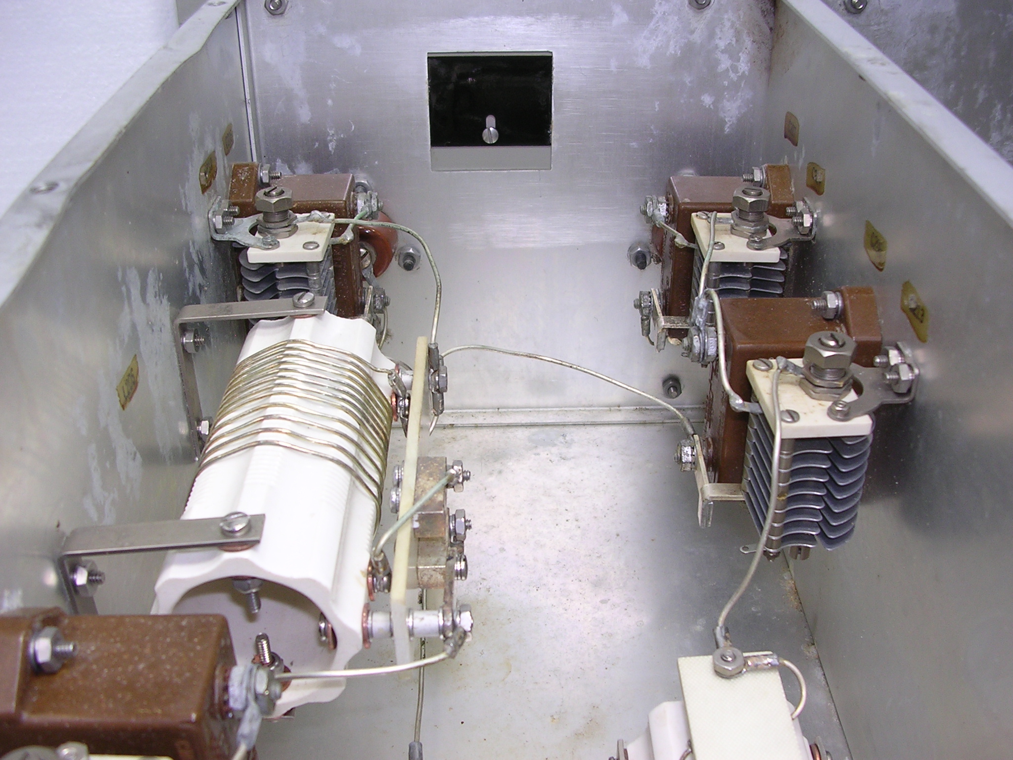
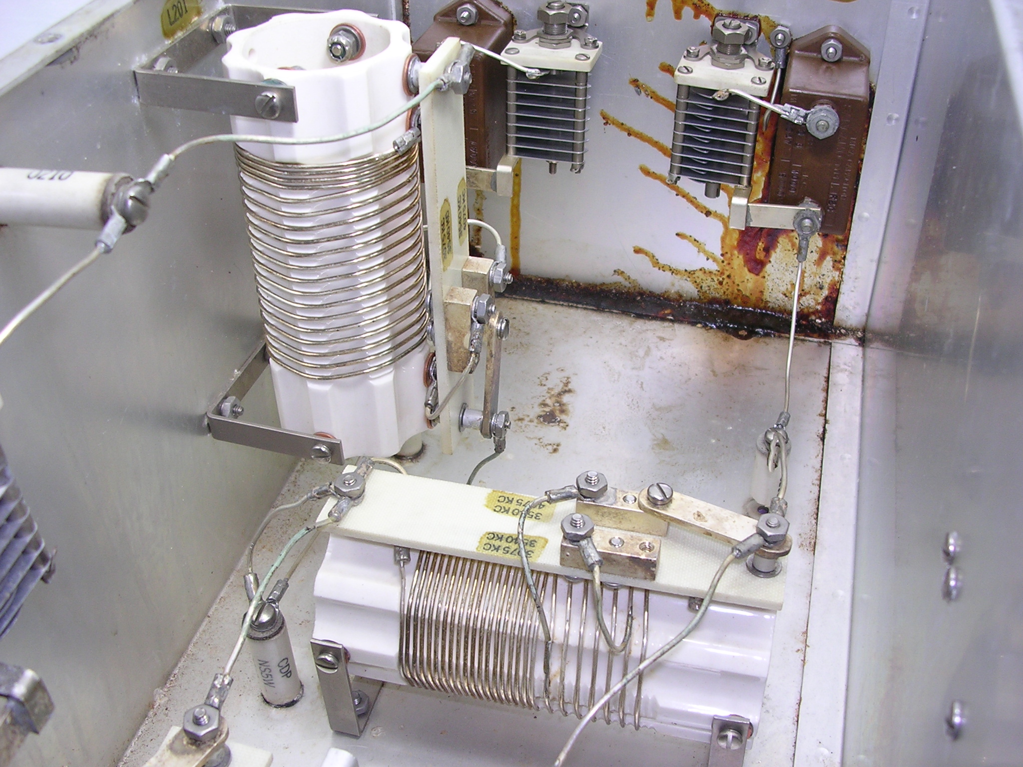
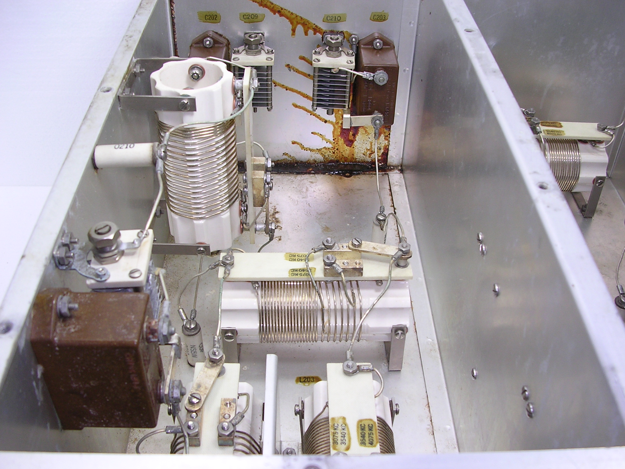
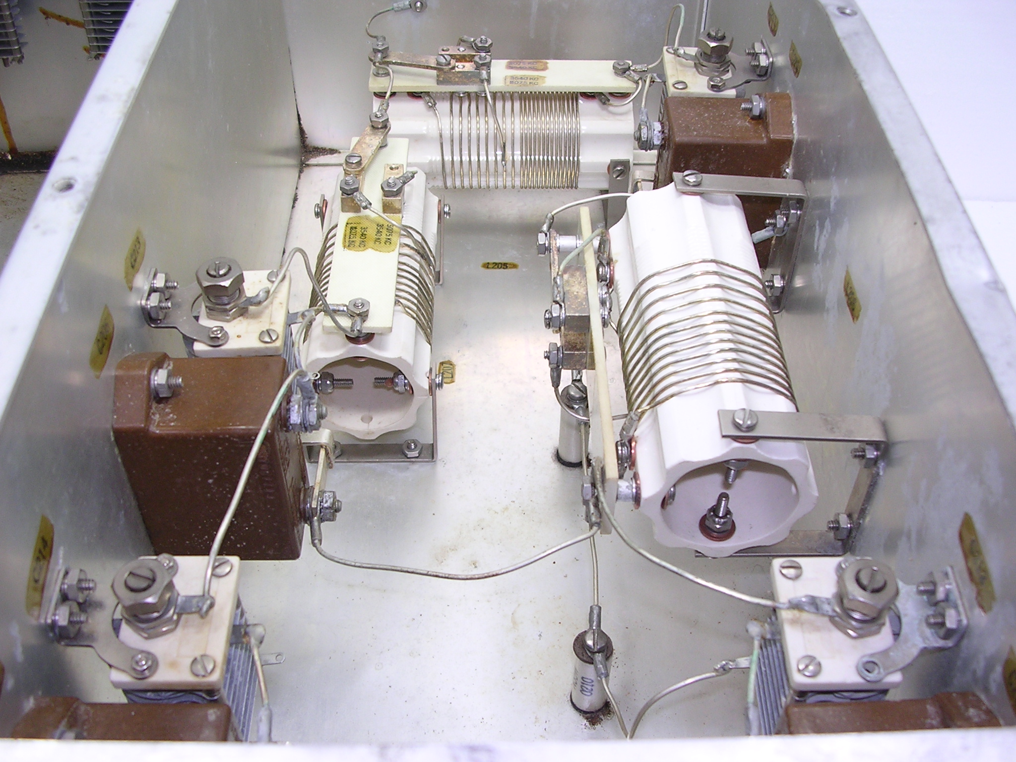
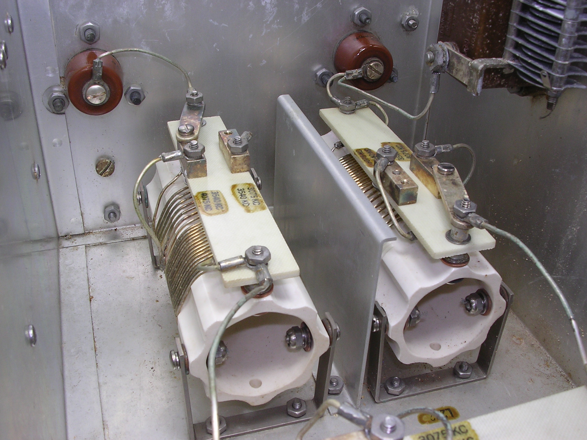
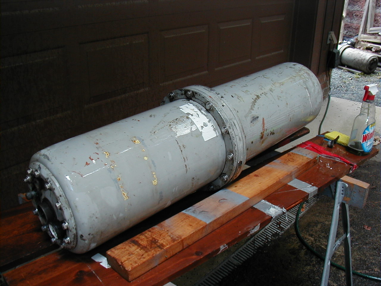
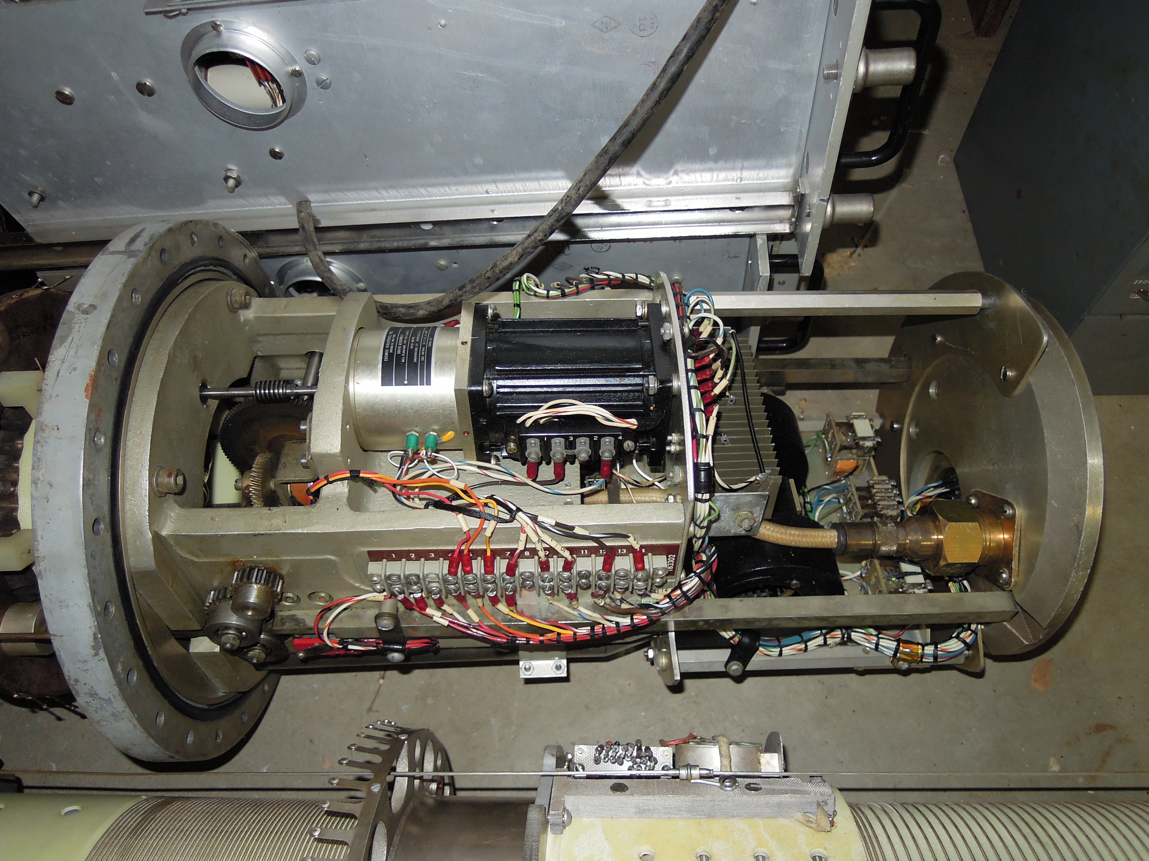
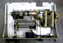
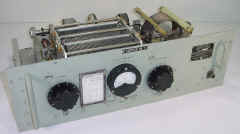
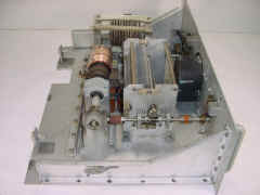
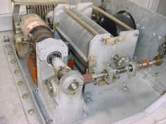
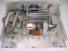
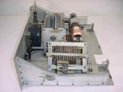
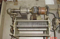
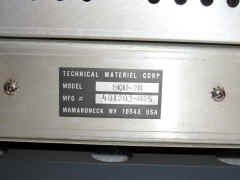
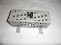
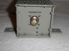
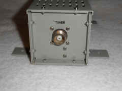
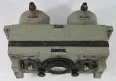
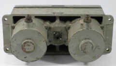
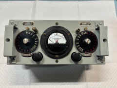
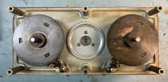
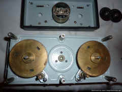
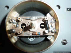
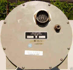
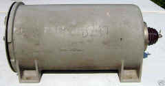
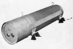
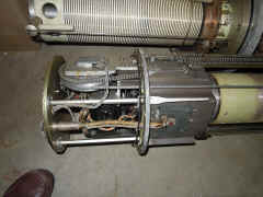
TN-342/WRT
antenna tuner for AN/WRT-2 transmitter
TN-342 pages from the AN/WRT-2 manual - Download 13 MB pdf
Photos of my
restoration job on a TN-342
|
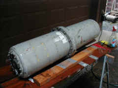
|
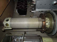
tuning coil end
|
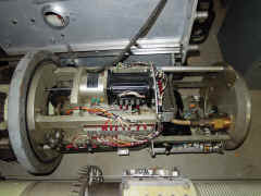
motor/control end
|