Airborne VLF - TACAMO
EC-130G, EC-130Q, and E-6 aircraft
- Transmitters - see page 10
- Receivers - see page 20
- 1978 magazine article
- Info Page Here
- More Info Here
- More Info Here
- More Info Here
- E-6B Tacamo video
- 1979 Tacamo/ELF report

The EC-130 had the four standard 40/50 KVA generators with an additional four 60/90 KVA generators for the nominal 200KW PA
 .
.


VERDIN - The AN/URC-62 System included:
SHORE TRANSMITTER- AN/URT-30 Transmitter
- CP-1071/WR processor
- MD-856/ART-50 Modulator
- O-1695/U Frequency Standard
- AN/ARR-77 Relay Receiver
- AN/ART-50 Relay Transmitter
- R-1738/URR Receiver
- CP-1071/WR Processor
- MD-855/WRR-7 Demodulator & Power Supply
- O-1612/URC Frequency Standard
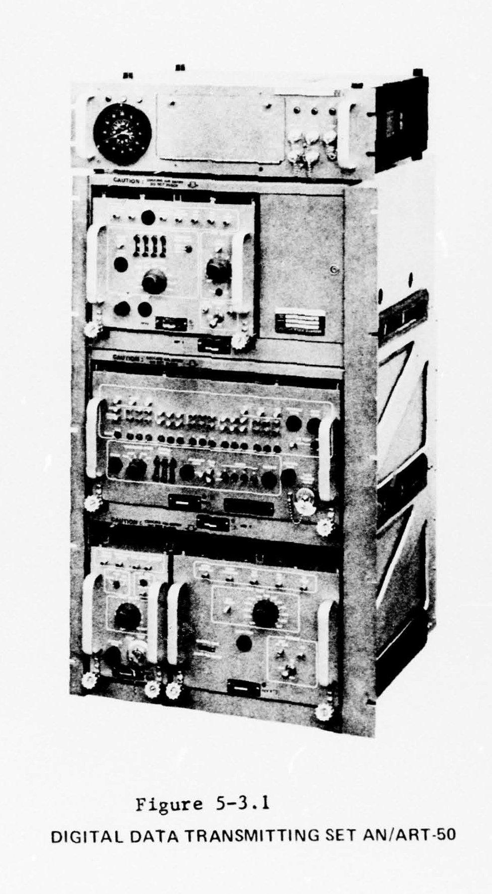

TACAMO radio equipment was manuf by Collins - please send e-mail if you have any more info
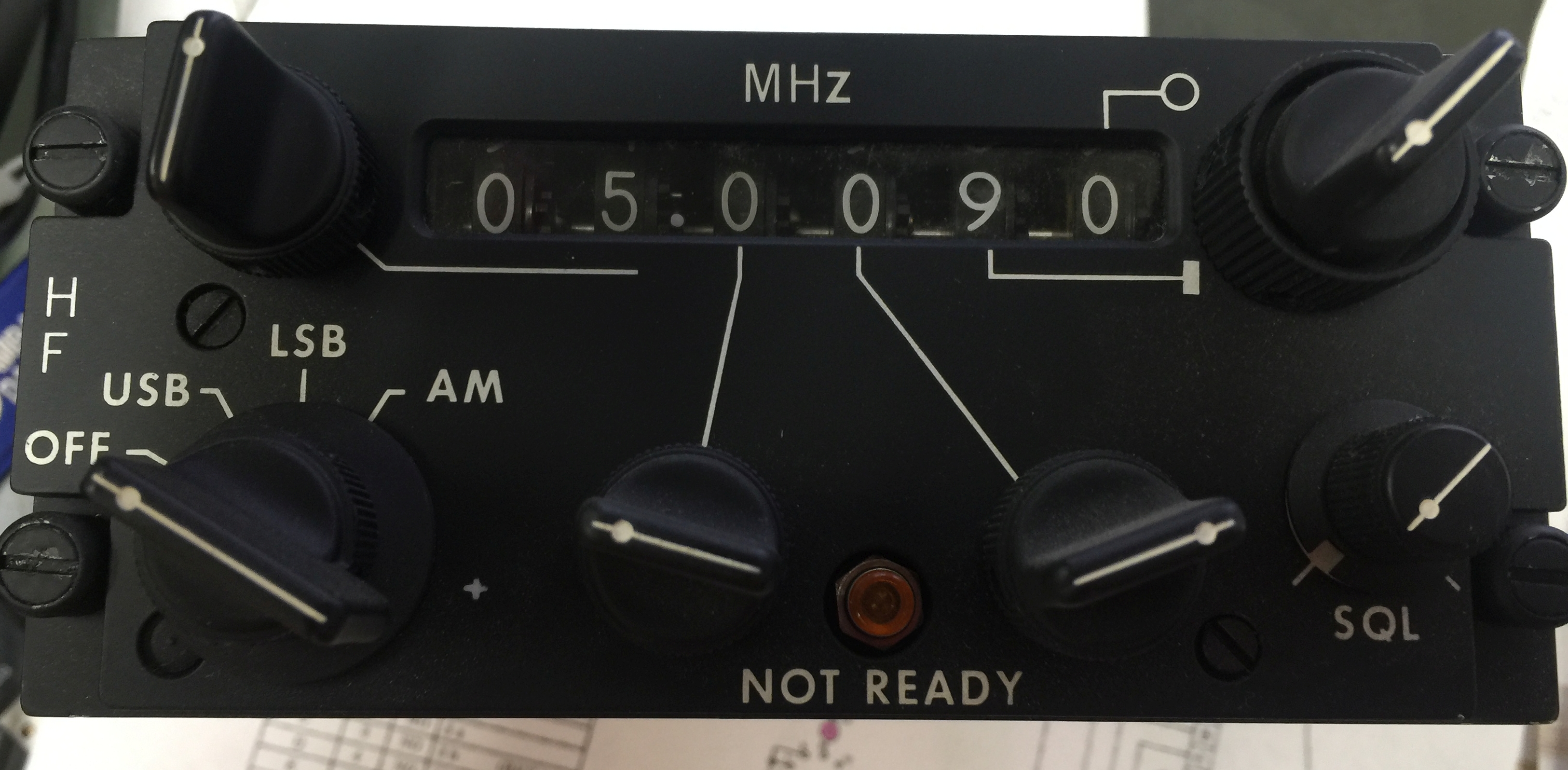
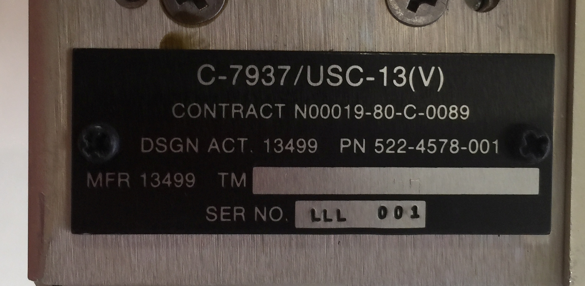
EC-130G is EC-130E with TACAMO communication system AN/USC-13(V)
installed.
I think the E-6A had the same system
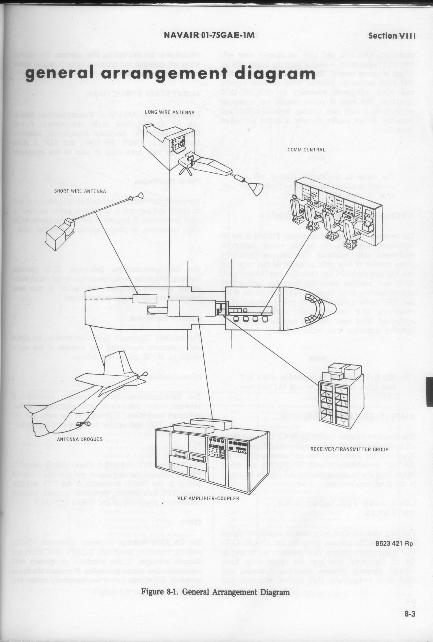
The 200KW tube-type transmitter is OG-193T/USC-13(V) Amplifier Coupler
Group.
E-6A TACAMO operators manual
The VLF set in the E-6B is OZ-1/USC-13(V) and the 200KW solid state transmitter is
the AN/ART-54 HPTS
Solid State Power Amplifier/Coupler (SSPA/C)
OG-187/ART-54
Dual Trailing Wire Antenna System (DTWA) OE-456/ART-54.
"Communications Central" system is AN/USC-14.
Info from http://www.public.navy.mil/AIRFOR/VQ4/Pages/Command-History.aspx
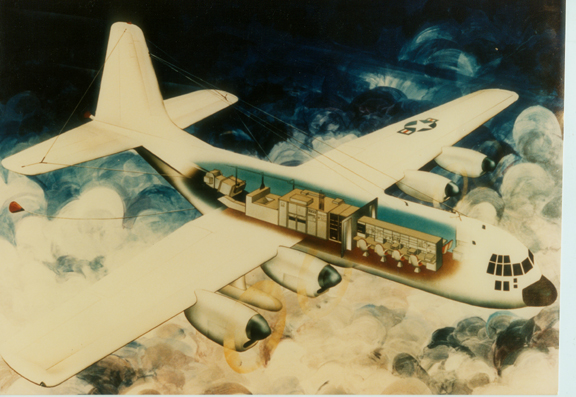
The TACAMO mission began in 1961 as a test program to determine if an airborne Very Low Frequency (VLF) communications system was feasible. Weapons Systems Test Division conducted this program, using a U.S. Marine Corps KC-130 aircraft as a test vehicle. The overwhelming success of the test program prompted funding for the first production aircraft. The project was designated TACAMO, which stands for “Take Charge and Move Out.”In order to avoid long lead-time delays, four U. S. Air Force C-130 aircraft were taken from the production line in early 1963. After extensive modification, the aircraft was designated a C-130G. The first of these aircraft, BUNO 151890, was delivered on 26 December 1963. At that time, the communications equipment consisted of removable vans that could be installed in a matter of hours. Plans were formulated in 1966 to expand the TACAMO Program. The expansion included permanently installing the communications suites in eight aircraft and their designation as EC-130Qs. On 1 July 1968, VQ-4 was established at NAS Patuxent River, MD as a permanent operational squadron. In 1974, the next major aircraft modification incorporated a new power amplifier, a dual trailing wire antenna system and a high-speed reel system for deploying and retracting of the trailing wire antennas. Additional improvements included satellite communications and an enhanced VLF capability.
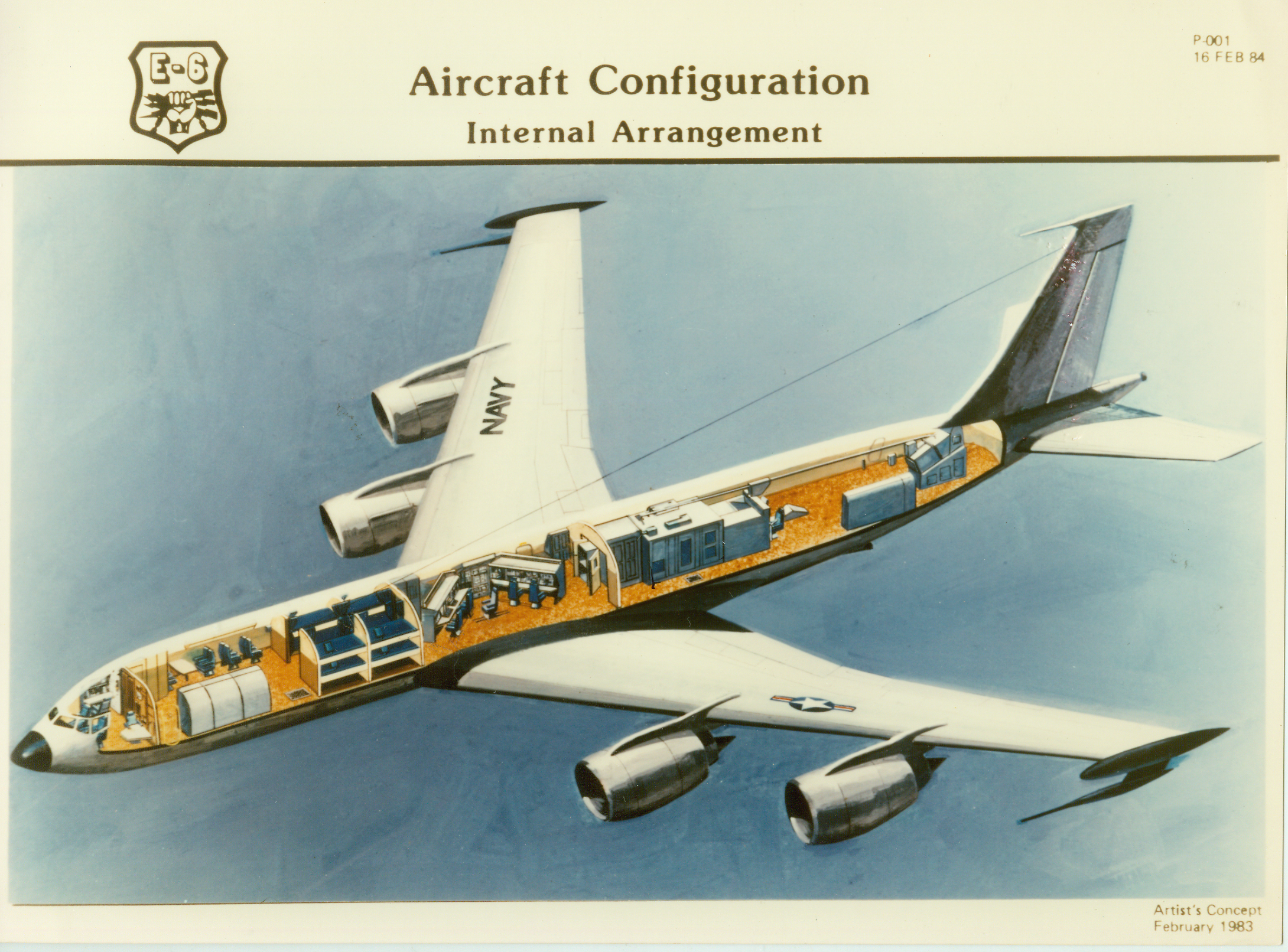
In the 1980s, it was recognized that the C-130s, in some cases the oldest in the fleet, were in need of replacement. The hunt was on for the successor to “The Mighty Herc.” Eventually, the B707-320 airframe was chosen, modified extensively and designated the E-6A. The Navy E-6s were the last 16 aircraft to roll off of Boeing’s venerable 707 line after 30 years of production. On 25 January 1991, VQ-4 took delivery of its first E-6A Mercury aircraft and in November 1992, changed homeport to Tinker AFB, Oklahoma City, Oklahoma. On 20 September 1999, VQ-4 took delivery of its first E-6B. The E-6B contains upgraded systems that enable it to perform the USSTRATCOM Airborne Command Post (ABNCP) “Looking Glass” mission. Upgrades include: a Battle staff module to provide enhanced command, control and communications for the Nation’s nuclear arsenal; the Airborne Launch Control System to permit airborne launch and control of ICBMs; UHF C3 Radio Subsystem; Digital Airborne Intercommunications Switching System; MILSTAR Airborne Terminal System (Satellite communications), and a High Power Transmit Set for enhanced communications.
Shipboard LF and VLF (SVLF)
Skyhook 1200' experimental LF antenna
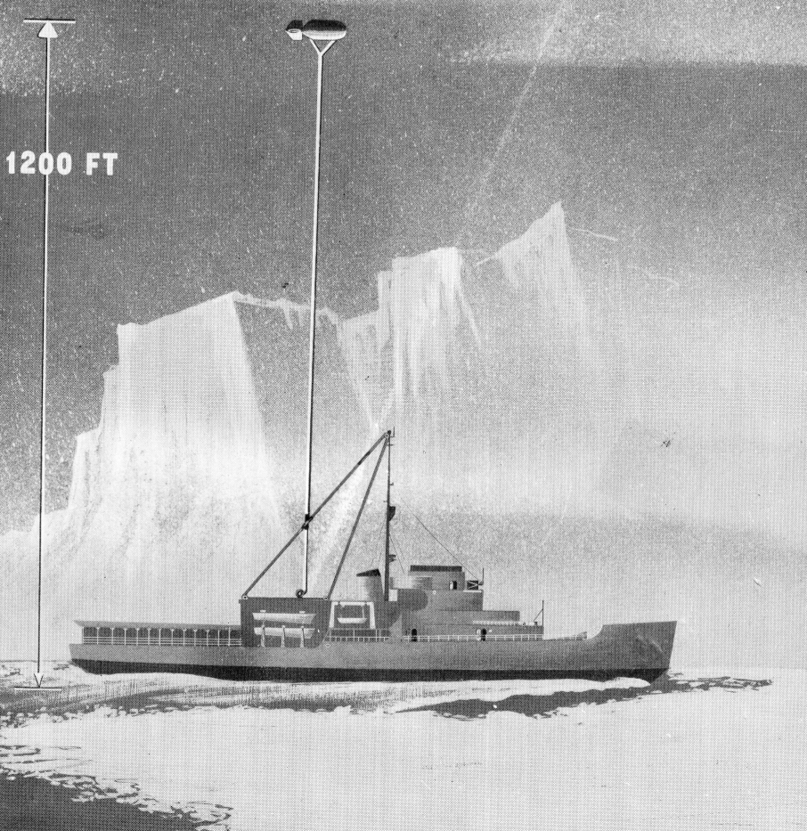
Shipboard VLF Transmitter with 10,000' antenna
USS Wright CC-2 had a 10,000' antenna hoisted by Kaman QH-43G helicopter (a balloon was also proposed but it is unclear if it was tested)
Please let me know if you have any info on the antenna, 250kw (275KW?) transmitter (GE?), etc.
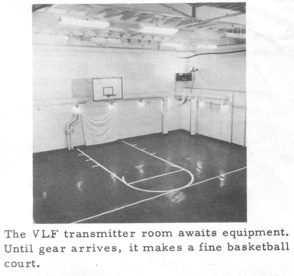
USS Annapolis AGMR-1 had a compartment scheduled for a VLF transmitter that was used as a basketball court. Please let me know if you have any info on the transmitter, antenna, etc.
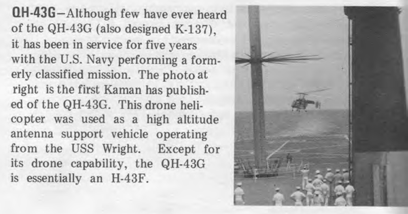
from Kaman magazine 1970
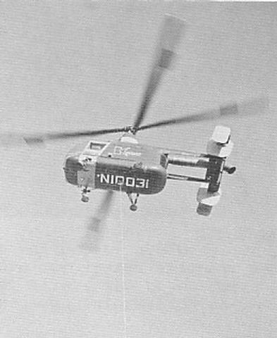
"We do not expect to have a perfectly vertical wire with the balloon, nor with the shipboard version of NOMAD, shown in figure 26, which employs a drone helicopter with a flight time of about four hours. We have plans, though they may never materialize, for an electric-powered drone helicopter which gets its current from the wire holding it down. Right now, we have no other progress than the investigative studies.
"The helicopter is unmanned because we felt that the presence of a man would then entail the presence of considerable equipment to ensure the man's safety. We would actually be trading fuel capacity and lift capability to include this additional weight. I suspect that the pilots might have reservations about flying with a wire hanging down."
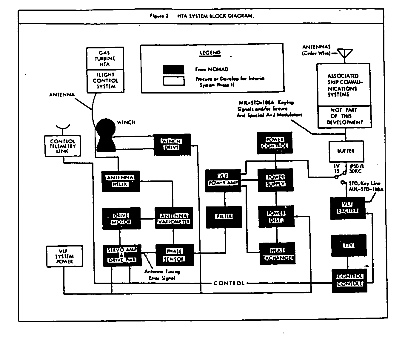
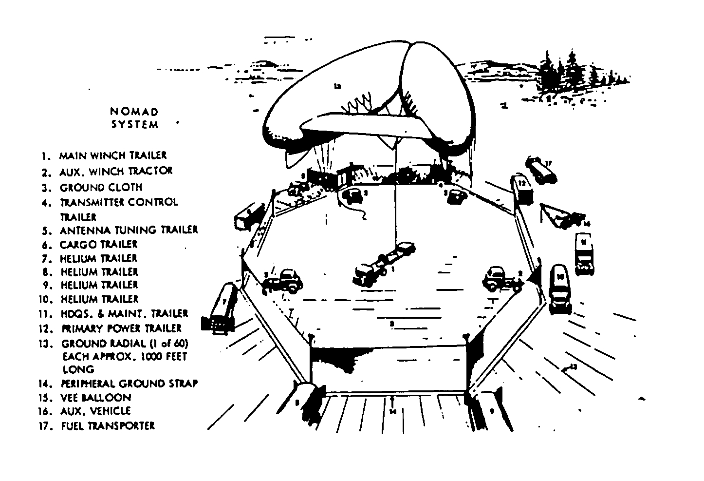
Transportable VLF - NOMAD & AN/MRC-99(XN-1)
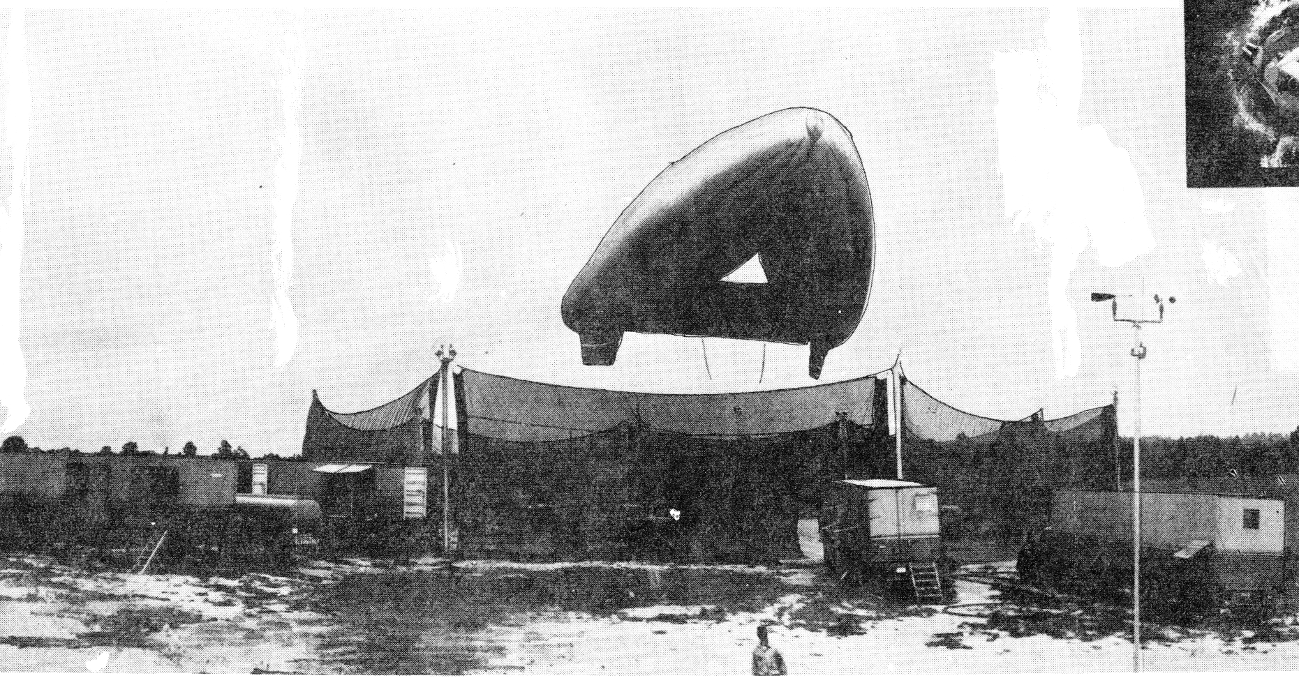
"Figures 24 and 25 show the equipment used in the NOMAD system. The unusual V-shaped balloon was developed for us by Goodyear Rubber and will be undergoing tests this summer. The length of each balloon section is about 100 feet and the design permits the best use of aerodynamics in launching and handling. Supporting the equipment in the balloon are about 12 vans fully loaded with transmitting equipment, helium gear, balloon handling gear, and the components of the wind-screen which is placed around the launch site to provide ease in handling.
"We have already flown the balloon at 3000- to 4000-foot altitudes. Operationally, there will be about 10, 000 feet of wire connecting the balloon to the ground and this wire will be the transmitting antenna. There is no problem anticipated in its actual operation; the wire is strong enough to handle winds of 50 miles per hour once the balloon is airborne. The tensile strength of the wire might be exceeded unless care is taken in the actual launching operations.
Components of AN/MRC-99 were used in later VLF experiments
AN/MRC-99 (XN-1) Transportable VLF transmitter experimental system
100kw, 15-30 kc
VLF/ELF Satellites?
Proposal
for a constellation of VLF/ELF satellites
10-20km (33,000-66,000 ft.) vertical trailing wire antennas
10kw transmitters at 1-3 kc.