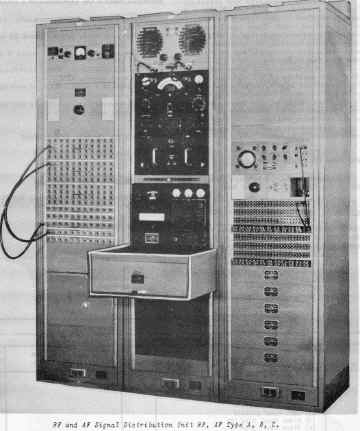
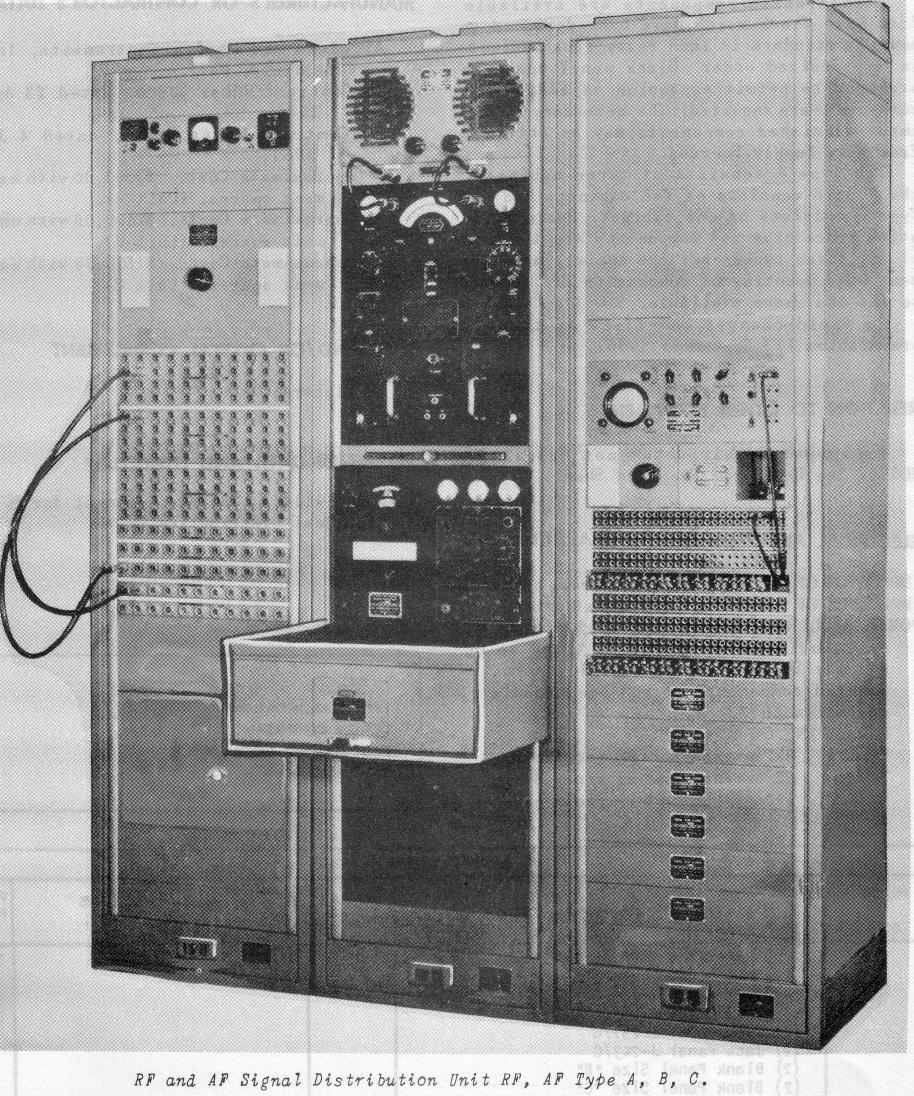
Navy Receiving Site RF and AF Signal Distribution Unit
- AN/FRQ-9 & SDU Type A, B, C
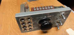
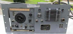
AN/FRQ-9 Monitor Set
|
Please let me know if you
have a copy of the AN/FRQ-9 manual for sale or loan for me to scan
|
--
|
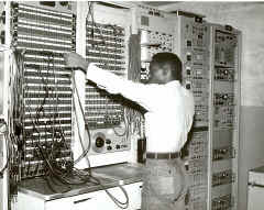
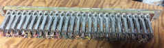
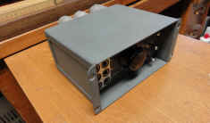
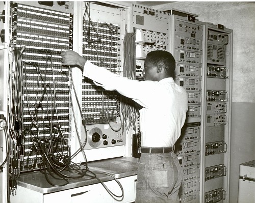
Patchboards at NAVCOMMSTA Guam
|
SDU Signal Distribution Unit
|
 |

SDU at NAVCOMMSTA Kodiak - 1959 -
Note R-390A replacing RBC receiver
-photo thanks to Tom Lawson |
|
 - - |
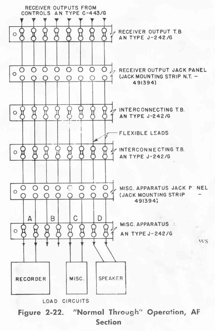
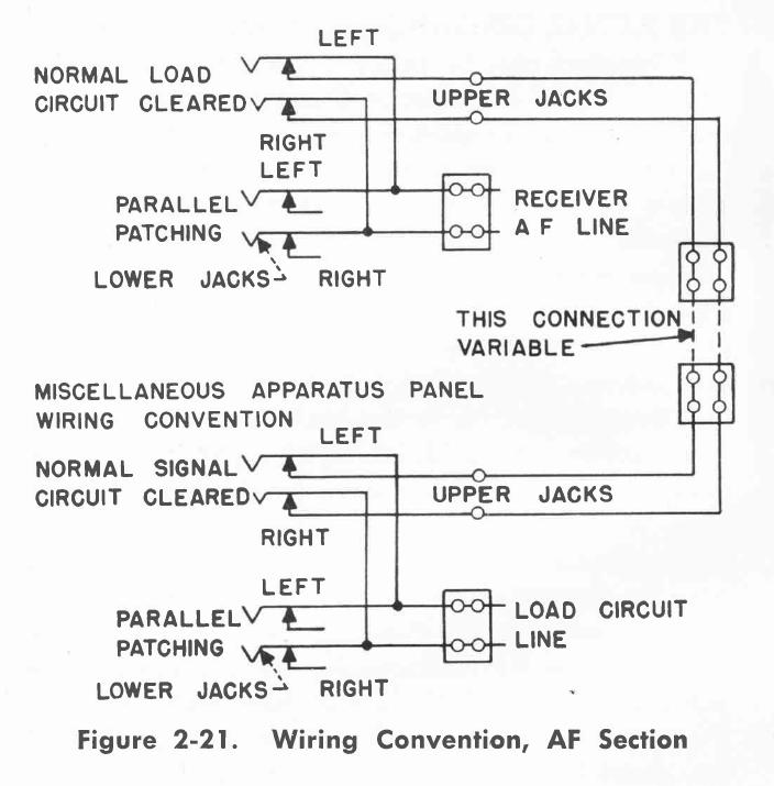
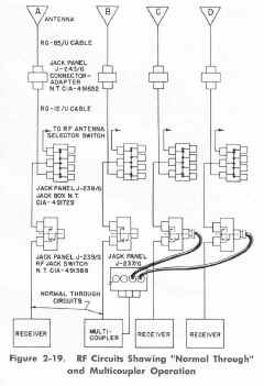
RF Wiring
|
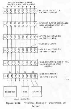
AF Wiring
|
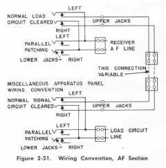
AF Jack Wiring
|
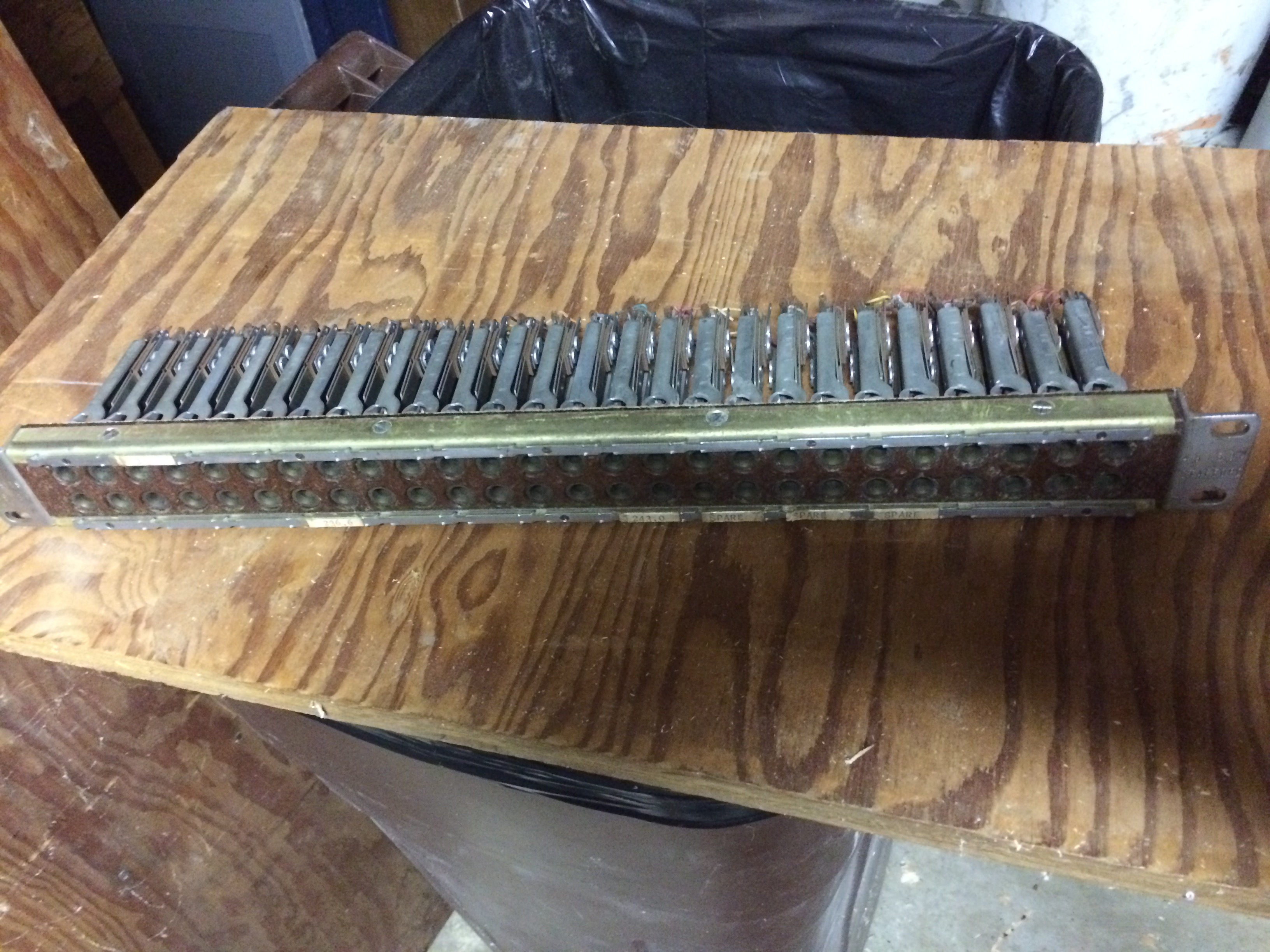
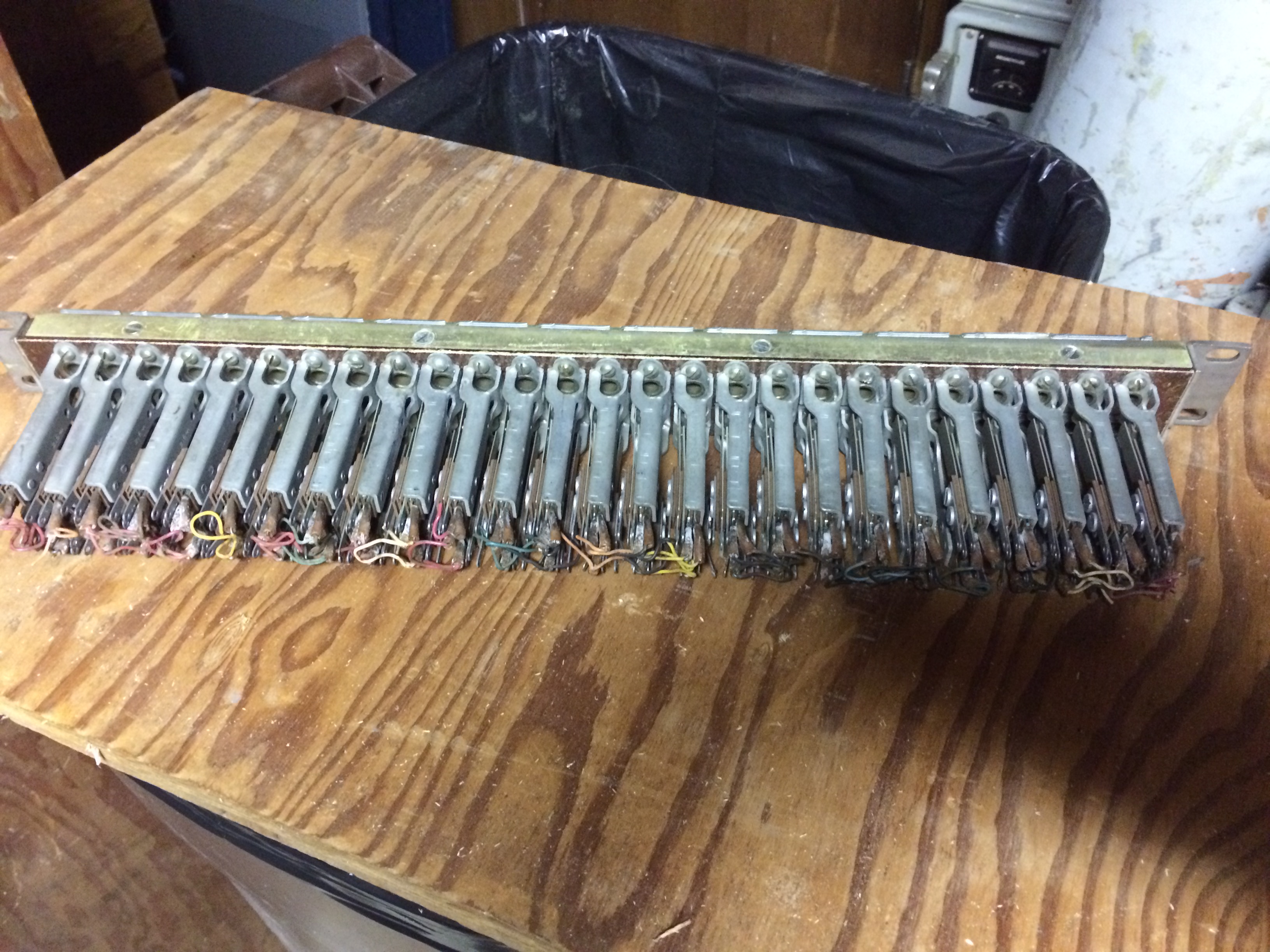
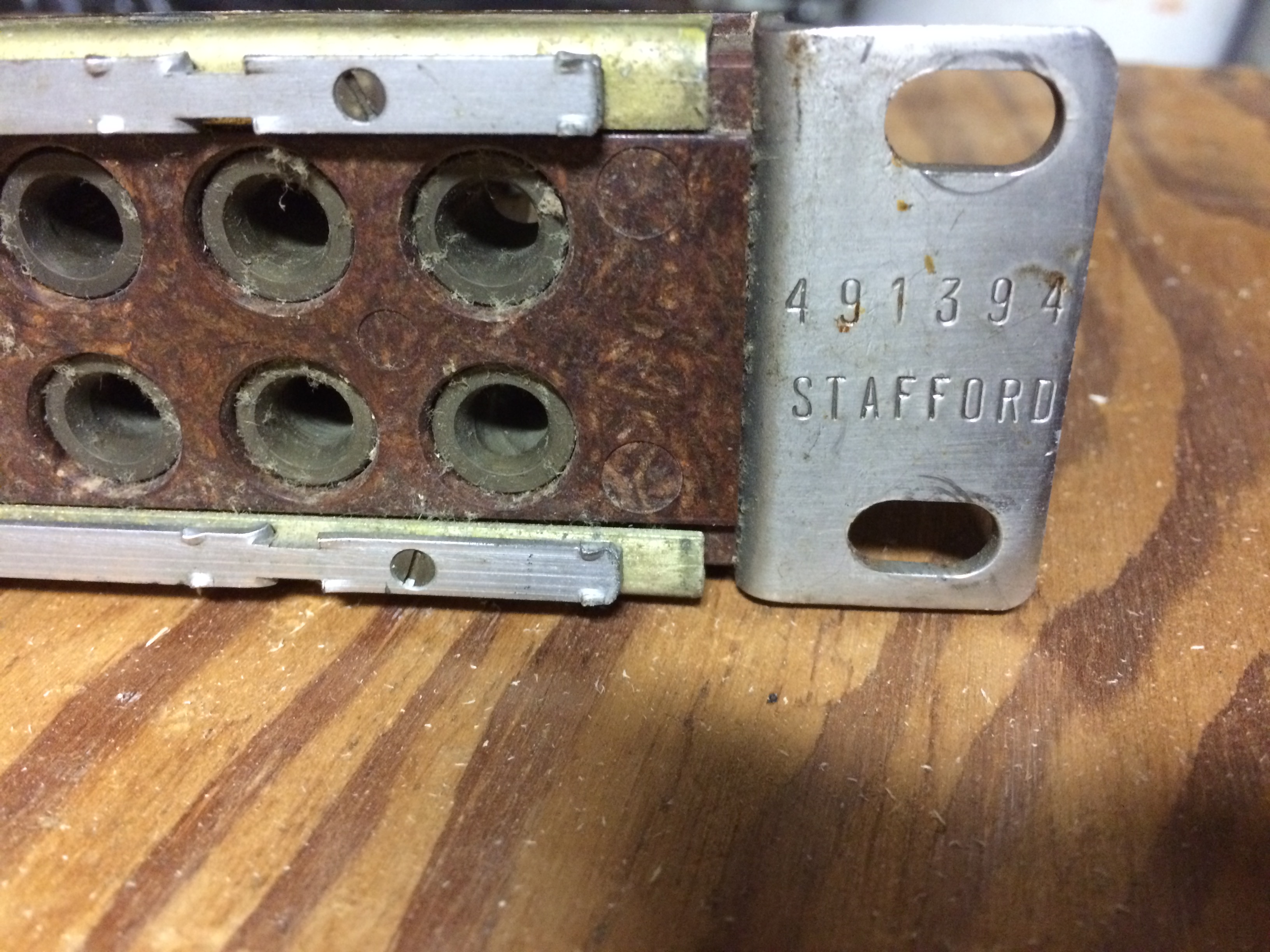
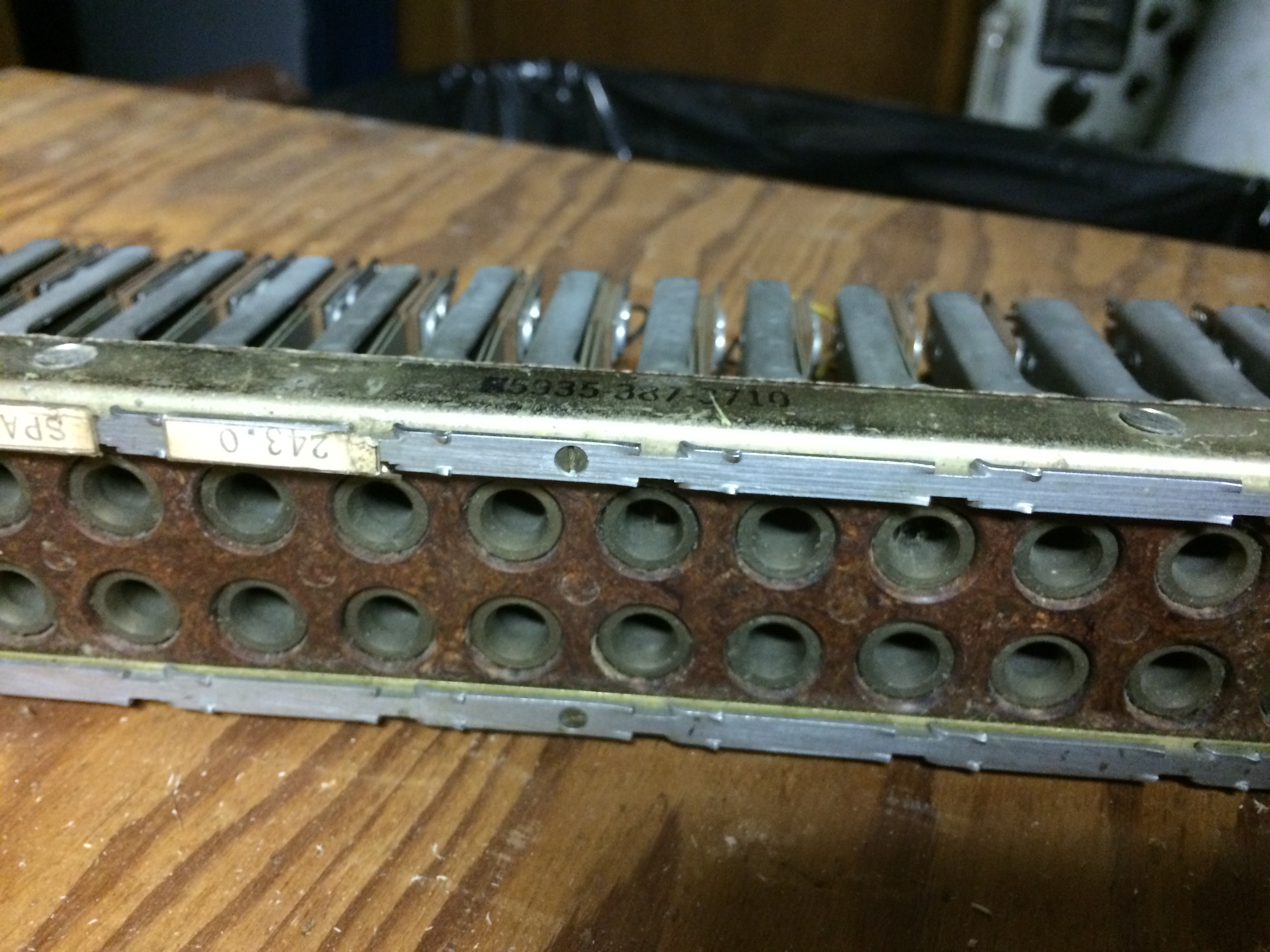
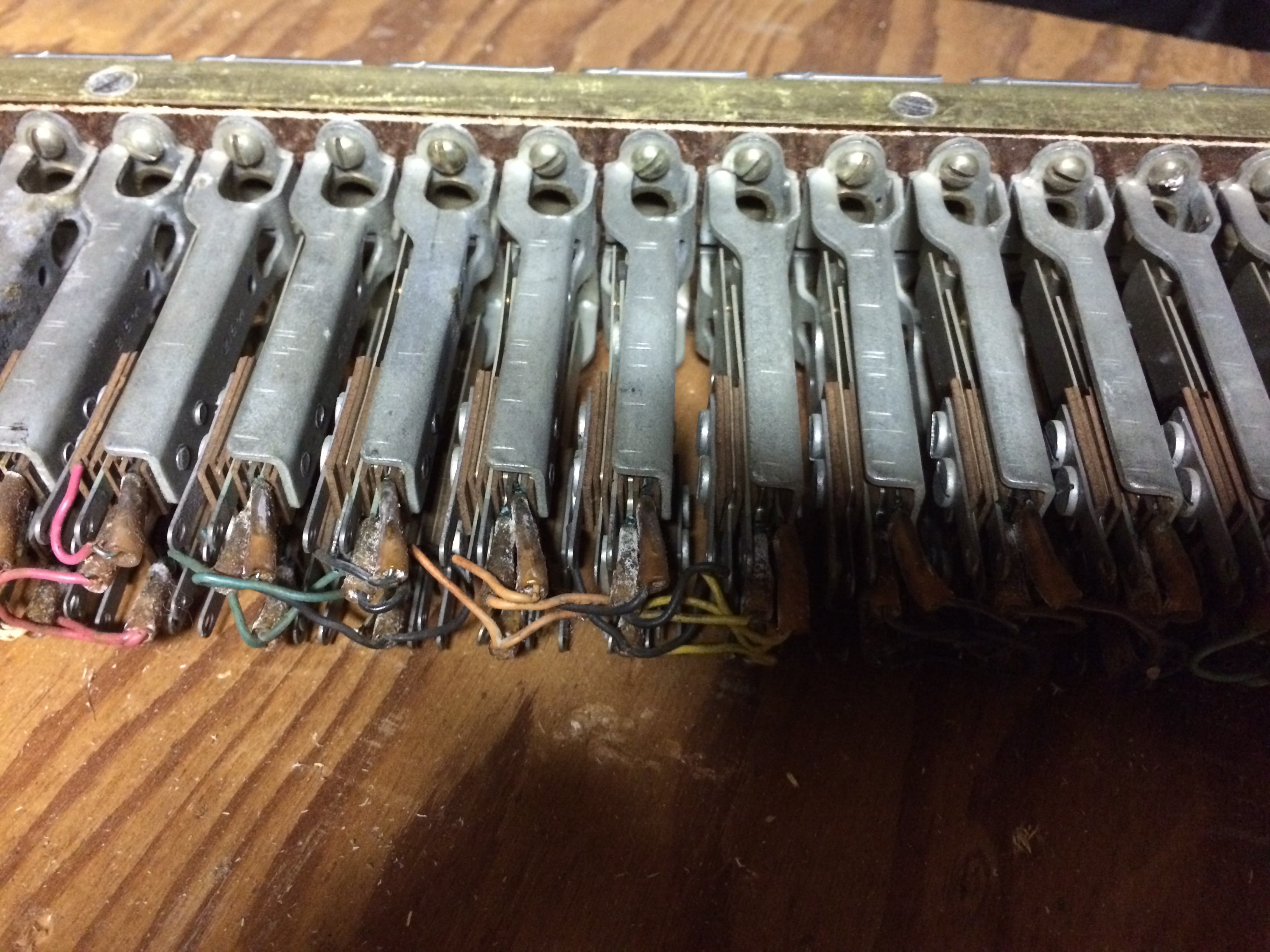
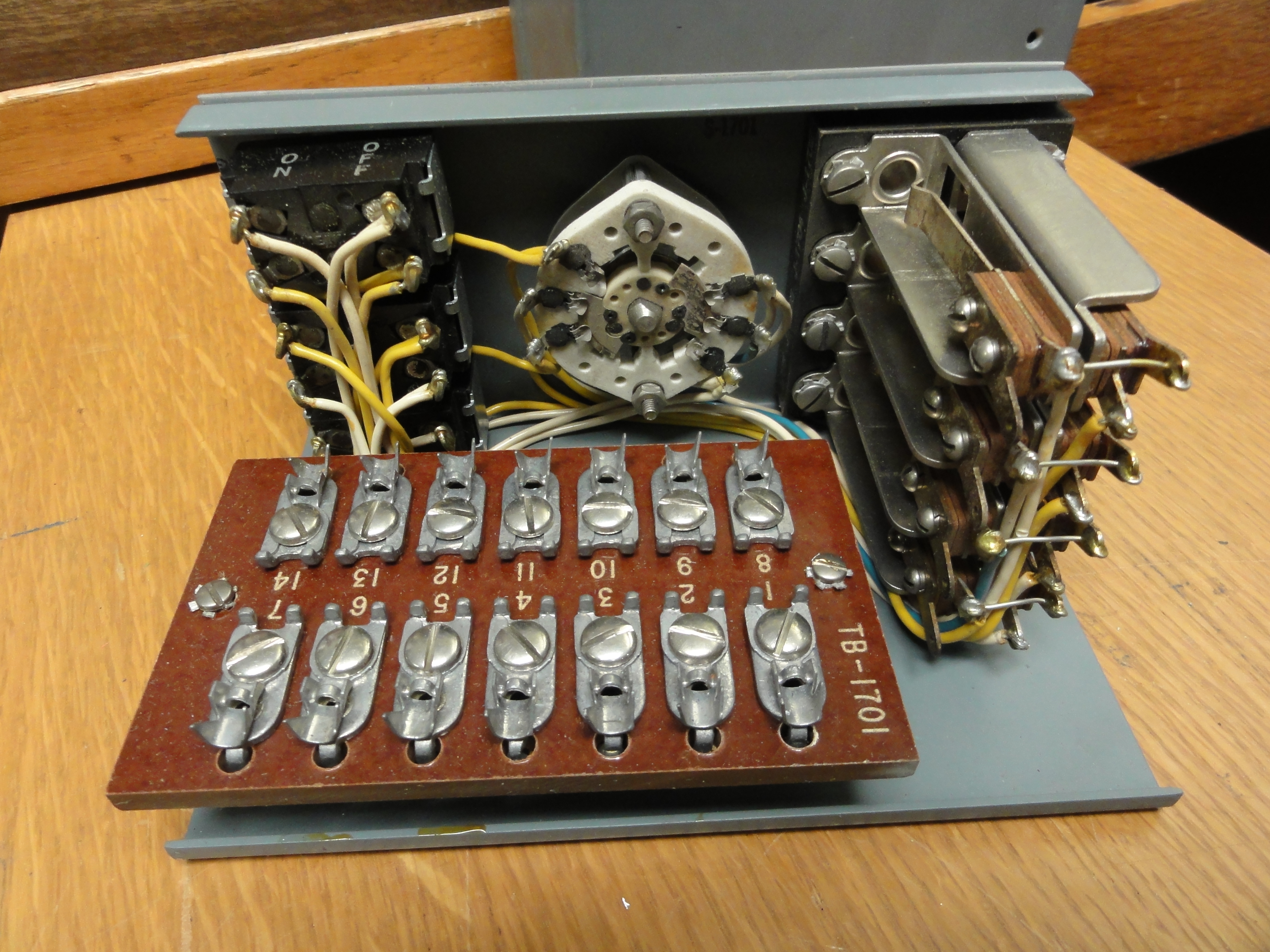
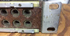
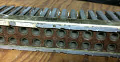
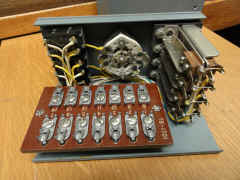
Navy Type -491394 is a size A panel which
includes mounting for 52 Telephone Jacks, Navy Type -491395, arranged in
two rows of 26 jacks each. Wiring, which is installed by the installation
activity, is so connected that horizontally adjacent pairs connect to the
two sides of a single circuit. Only the tips of the twin plug patchcords
make connection. The vertically adjacent jacks are connected in parallel
in such a fashion that when a patchcord is inserted into the top pair, the
normal circuit to the load is broken and a new connection substituted; but
when a patchcord plug is inserted into the bottom jacks., the normal
circuit is unaltered and the patchcord is then in parallel. Thus, a total
of 13 circuits may be connected into any one lack Mounting Strip. |
NT-491394 Audio Jack Panel
|
Two rows of 13-pairs, 2-conductor
|
|
|
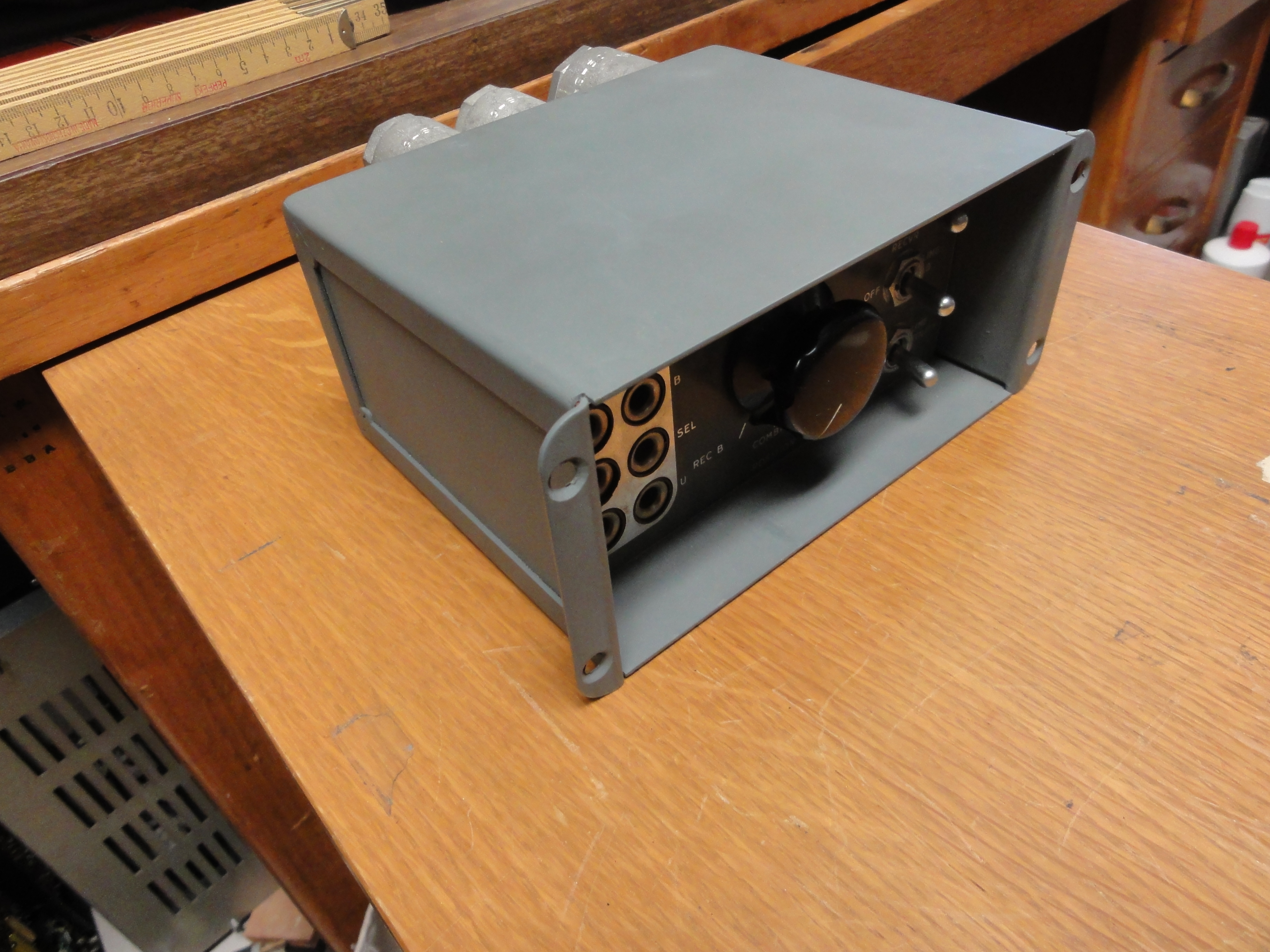
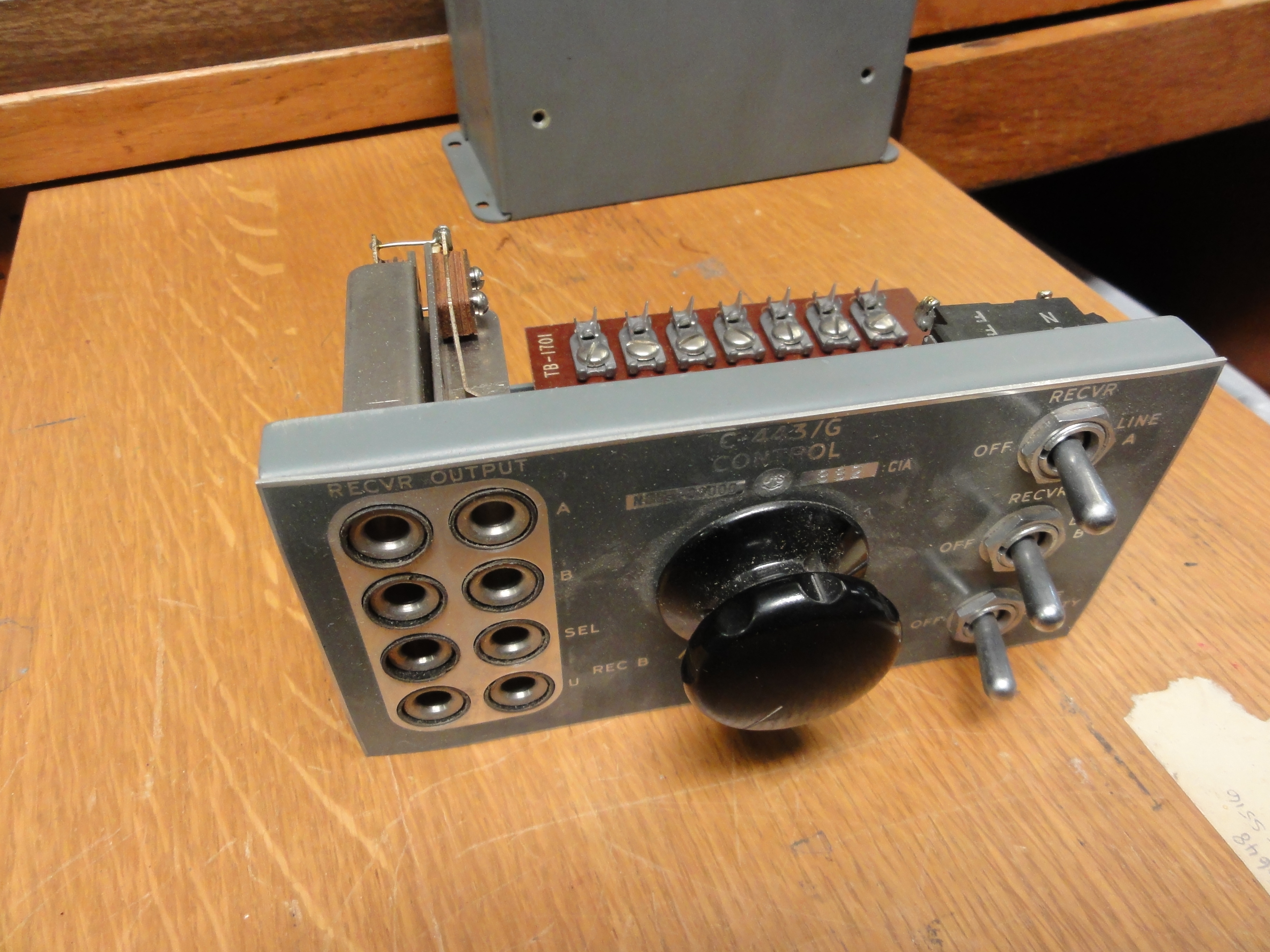
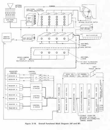
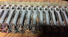
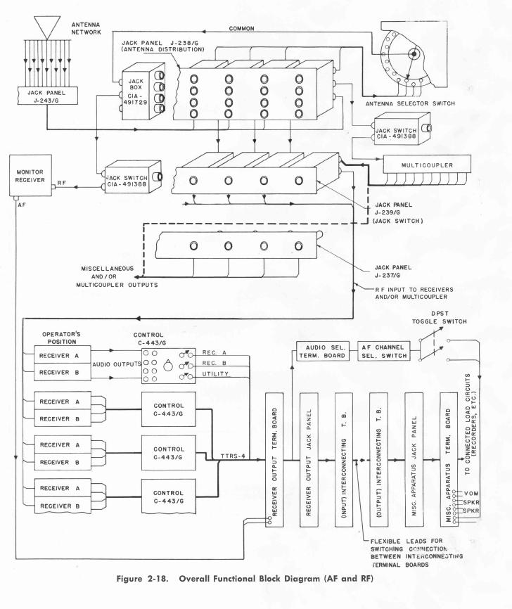
Control C-443/G
Control C-443/G is the connecting link between the Signal
Distribution Unit and the AF output from two radio receivers at each
operator's position within the station, or any remote position included in
the Distribution System. This component which is designed for mounting
under the front edge of a Standard Navy Operator's Table consists
essentially of a three position rotary selector switch used for selection
of either or both receiver outputs to the operator's phones, a set of
toggle switches for connecting the receiver audio circuits to the
Distribution Unit, and four pairs of phone jacks for the operator's
headset connections. The operator's headset is normally connected to the
set of jacks designated "SEL" which permits either or both
receiver outputs to be impressed on the phones by the action of the three
position rotary selector switch. The set of jacks designated "U"
may be connected from a utility line to the operator's position. The jacks
marked Receiver "A" and Receiver "B" are connected in
parallel with the receiver outputs and are used to connect the operator's
headset to each receiver without the use of the selector switch. The
construction of all jacks is such that headsets equipped with Navy Type
-49109 single plugs are inserted in the left hand jack, and those equipped
with Navy Type -491242 twin plugs are inserted in both jacks.
The toggle switches connect the receiver outputs to the
audio lines between Control C-443/C and the Receiver Output Terminal
Boards J-242/G. With the switches open, the operator has the receiver
outputs available at his phones, and the selector switch permits either or
both receiver outputs to be heard. |
C-443/G AF Control and Jack Box
- installed at each receiver operating position
 |
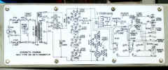
C-443/G schematic
|
|
|
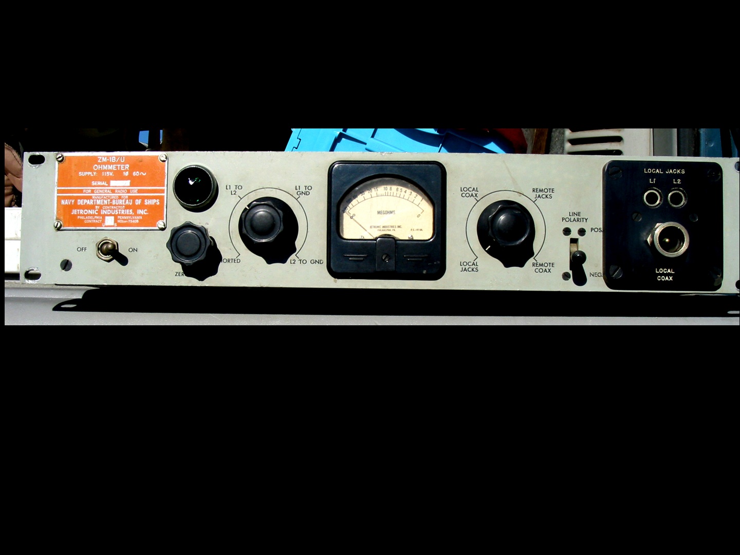
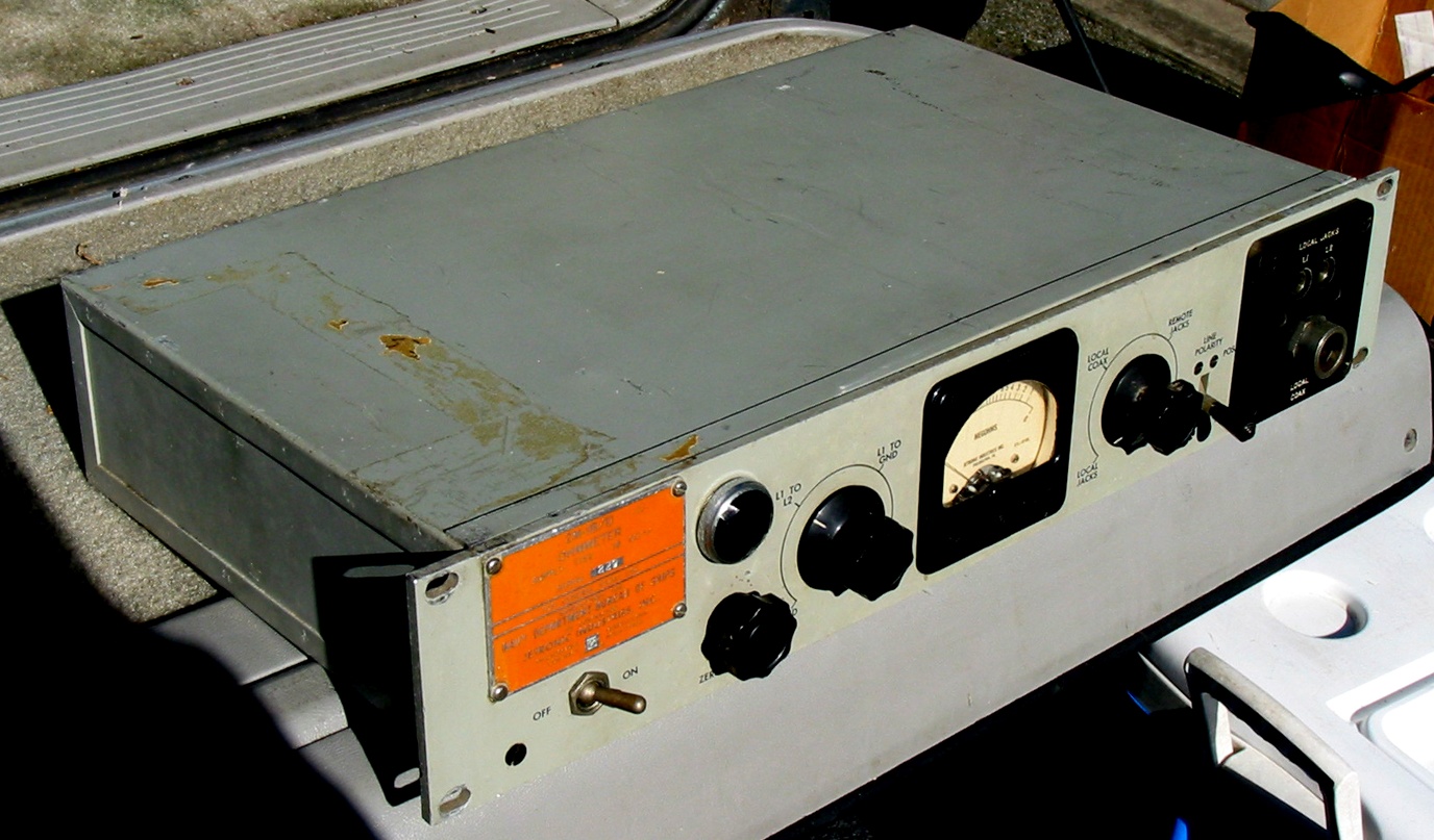
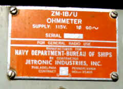
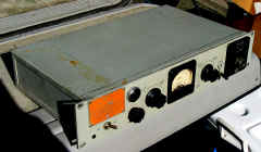
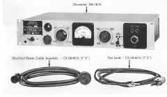
ZM-1B/U Ohmmeter
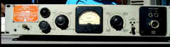
Please let me know if you have
one for sale or trade
NAVSHIPS 92086 pdf
|
 |
 |
|
|
|
|
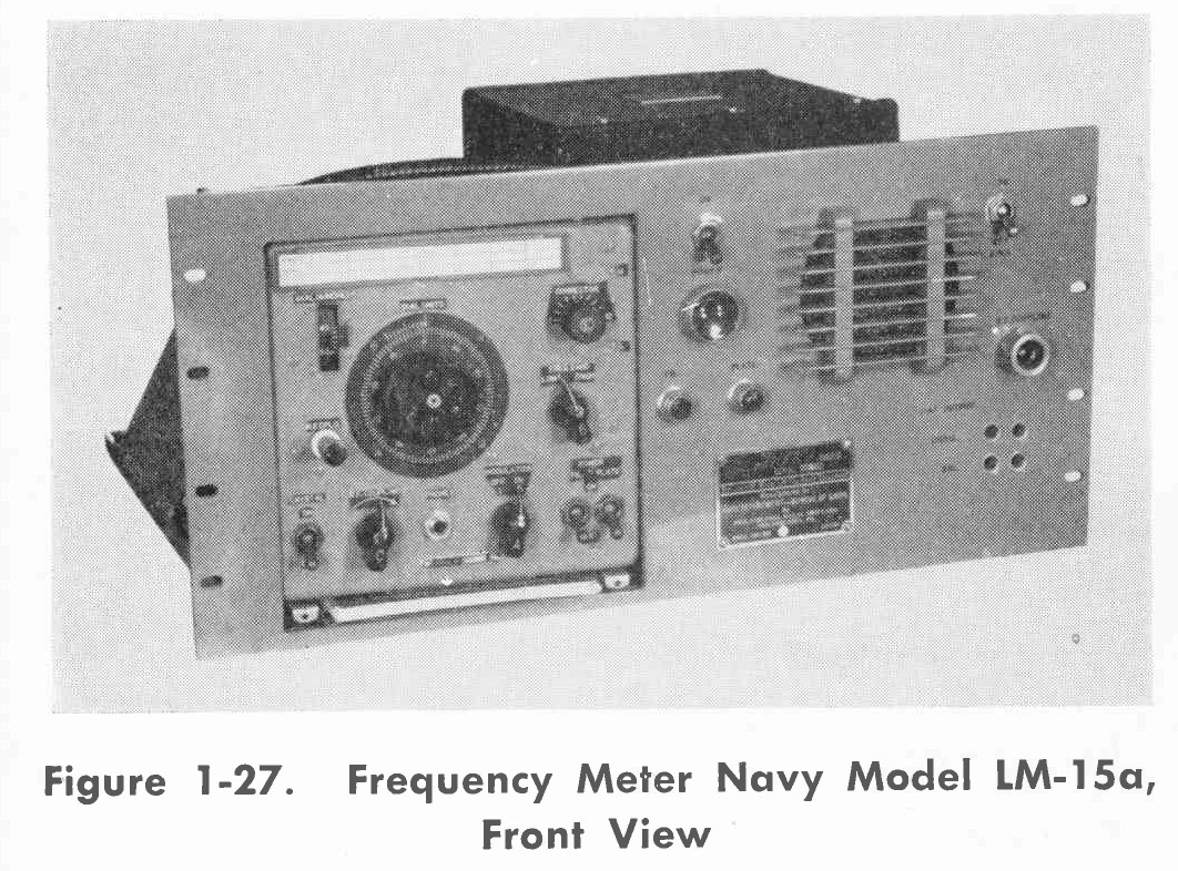
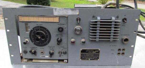
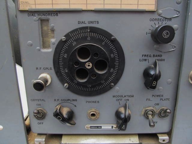
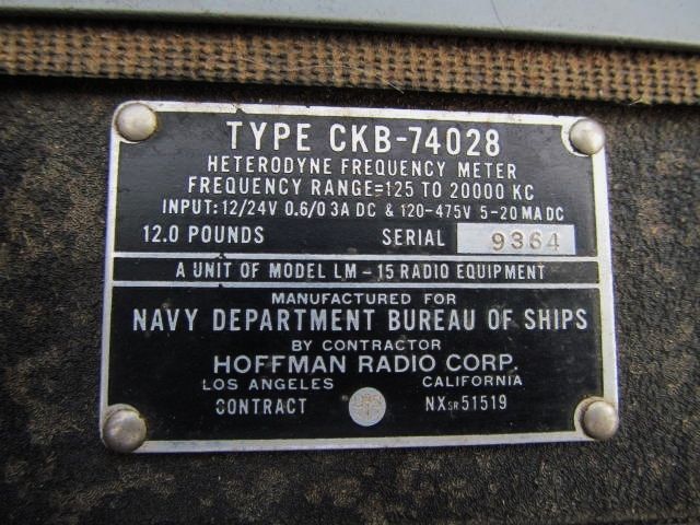
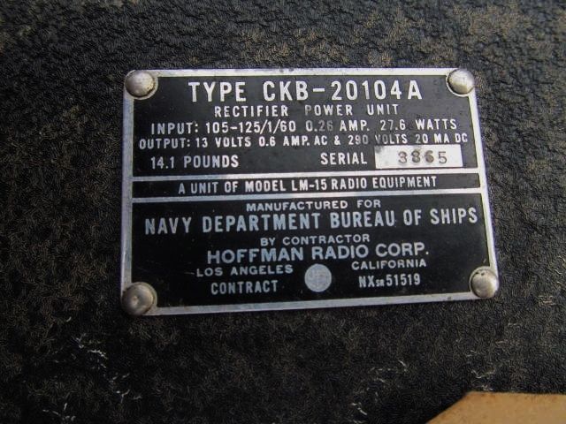
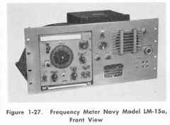
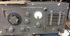
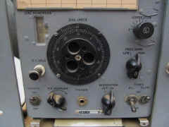
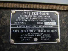
LM-15A frequency meter in RL-10624 mount
Please let me know if you have
one for sale or trade- used in Type C SDU
|
|
|

|
 |
|
|
|
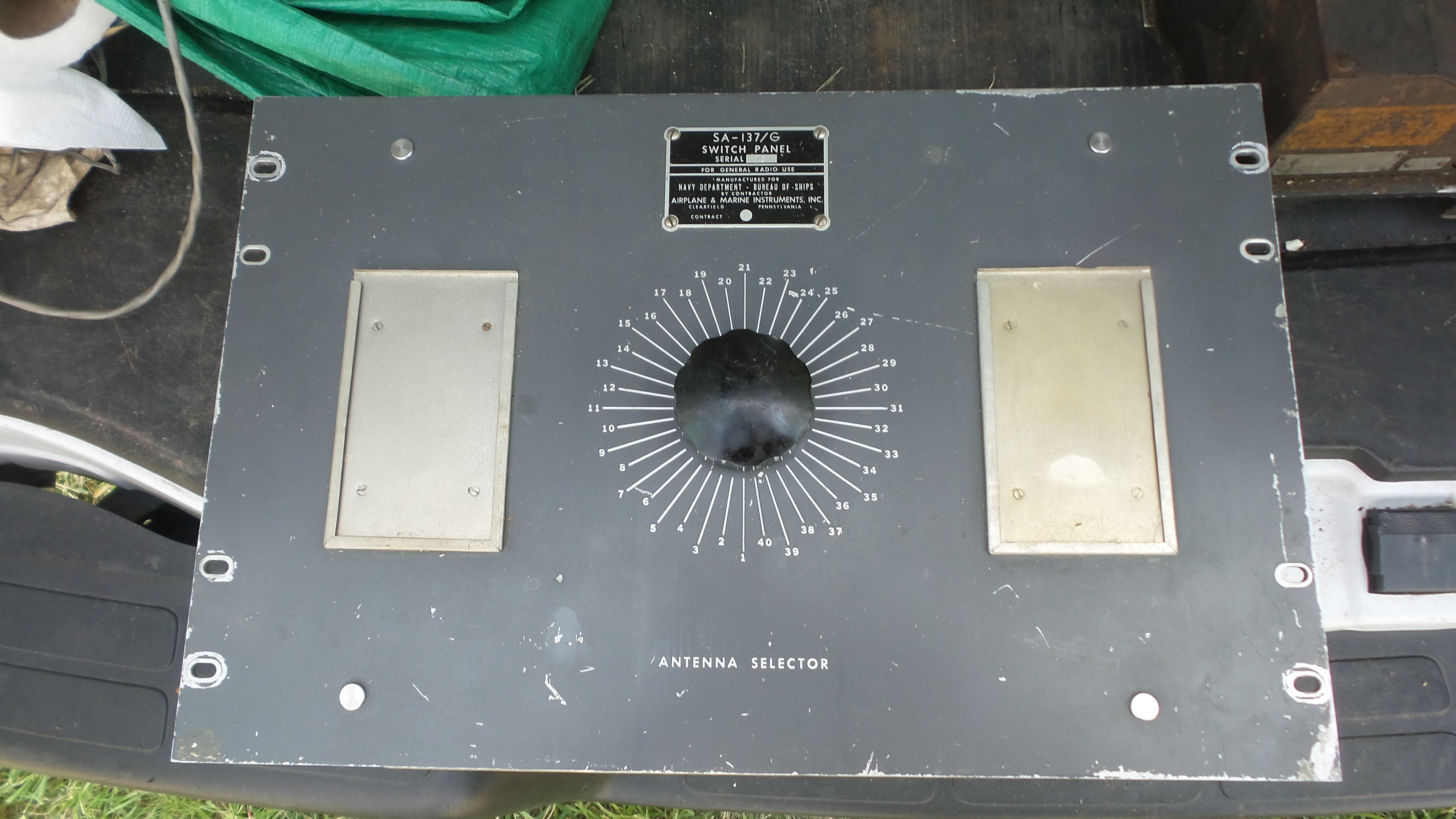
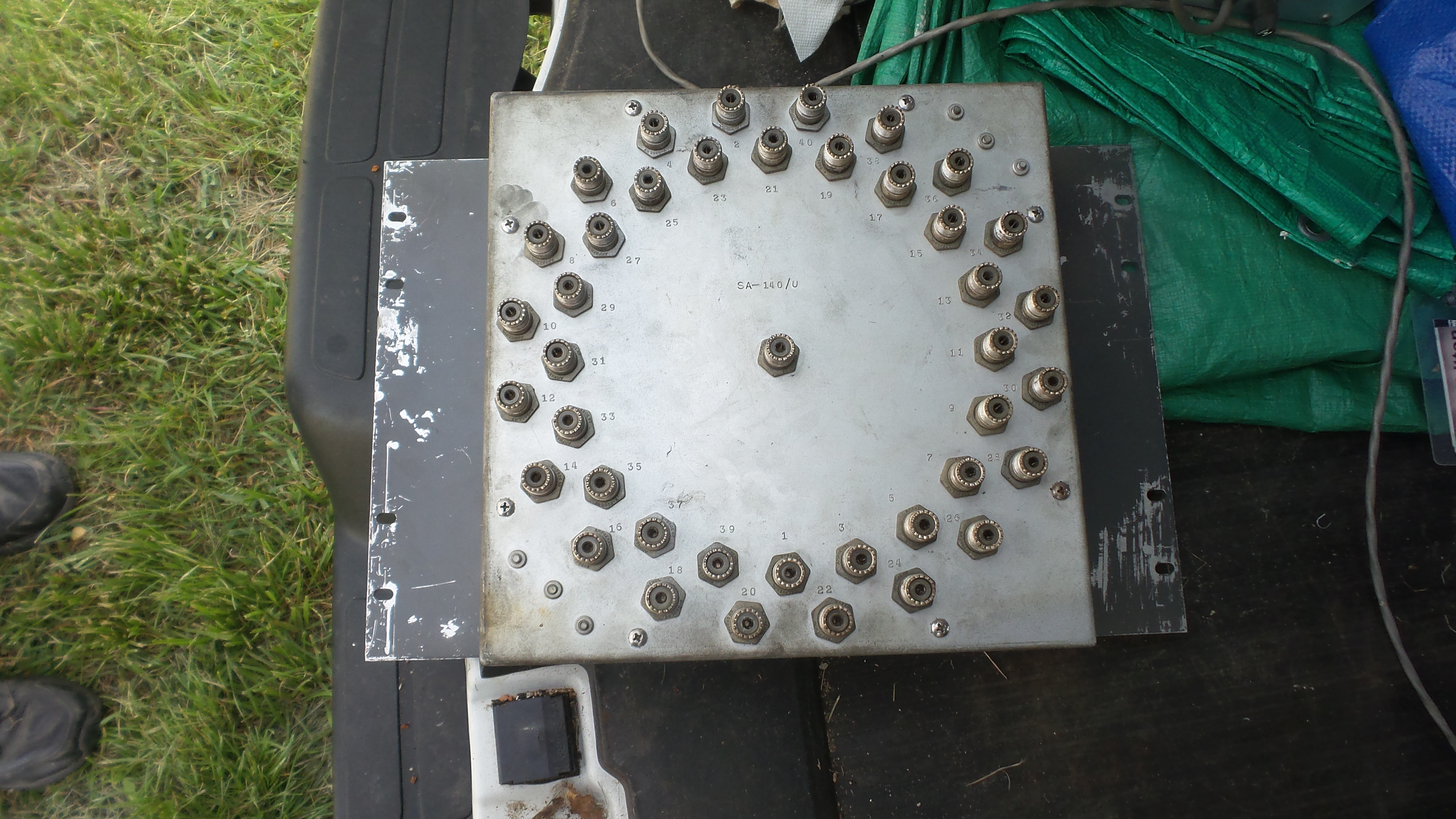
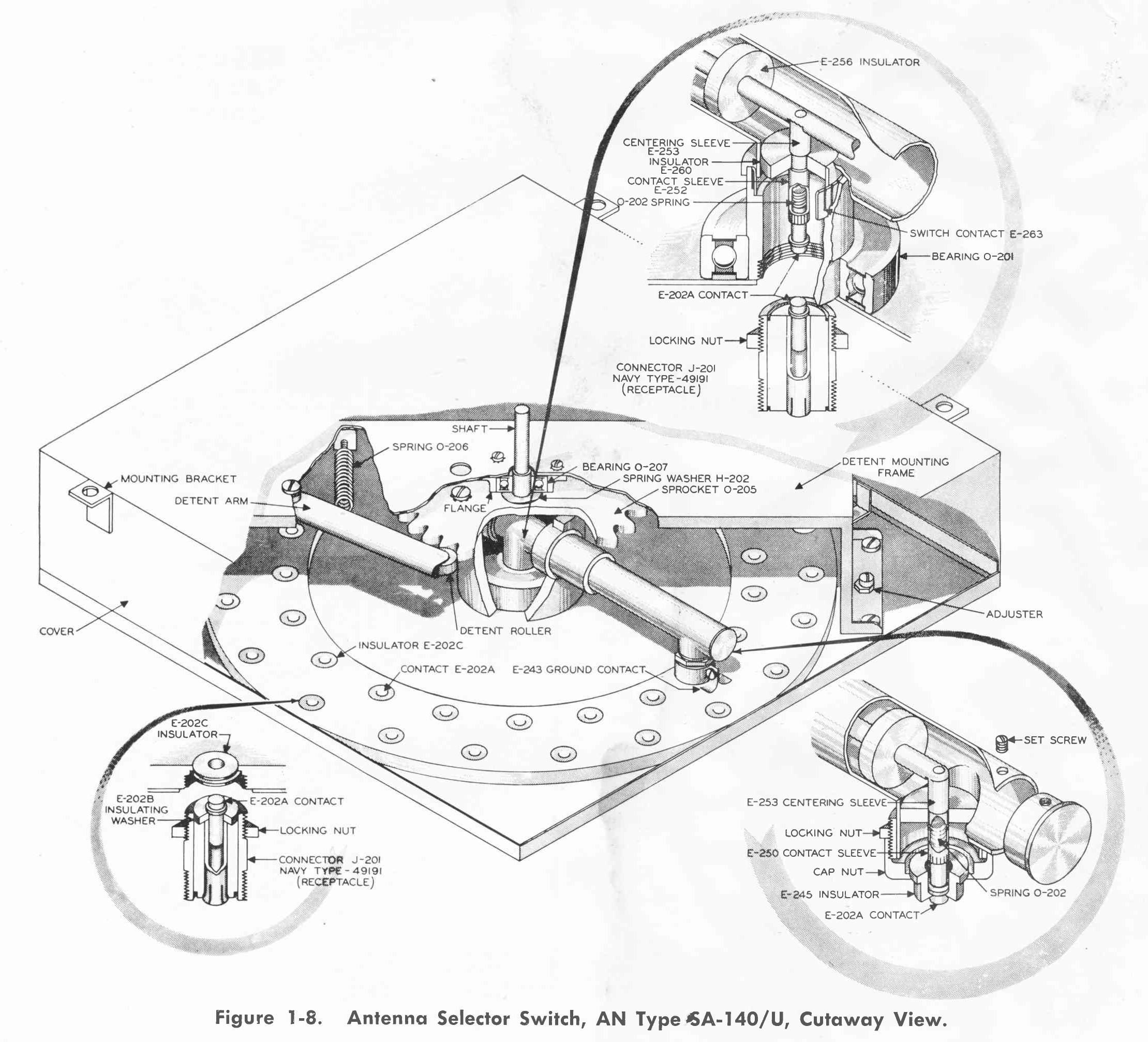
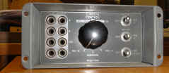
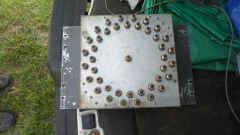
SA-137/G
|
SA-137/G
 |
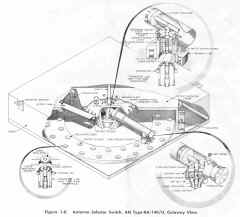 |
Manual RF switch panel used in shore station installations
SA-136/G is 20 position panel using SA-139/G switch
SA-137/G is 40 position panel using SA-140/G switch
SA-138/G is 60 position panel using SA-141/G switch |
NAVSHIPS 91047 SDU Manual - 36 MB pdf
download
(thanks to AWA library)
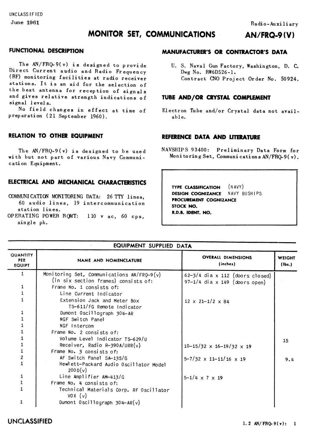
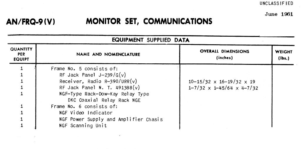
FUNCTIONAL DESCRIPTION
The Navy Signal Distribution Unit Type A, B, and C are standardized RF and AF manually operated switching
and monitoring equipments for use in Naval Shore communication centers. These equipments permit
standardization of components, method of installation and maximum operational flexibility when installed.
Standardized components are available from Navy Stock which have been designed to mount in standard 19
inch relay rack cabinets in any desired order. Blank panel space is provided to permit expansion as additional
components are required. The necessary Government furnished components may be obtained from Navy
Supply Sources.
The Type A consists of three cabinets, the Type B consists of two cabinets and the Type C consists of one
cabinet,. Basic operating procedures and components are the same of all three types, but the number,
arrangement, and mounting of components are altered to fit the space available.
ELECTRICAL AND MECHANICAL CHARACTERISTICS
- IMPEDANCE OF RF COMPONENTS: 70 ohms nominal.
- IMPEDANCE OF RF LOADS; 600 ohms nominal.
- POWER REQUIREMENTS: 115 v ±10%, 58 to 60 cps single ph, or 230 v ±10%, 58 to 60 cps may be
substituted if all internally mounted components served are capable of operation on 230
v.
- CONNECTING CAPABILITIES
- TYPE A: 32 antenna and 32 receivers.
- TYPE B: 22 antenna and 22 receivers.
- TYPE C: 11 antenna and 11 receivers.
MANUFACTURER'S OR CONTRACTOR'S DATA
Airplane and Marine Instruments, Inc.; Clearfield, Pa.
Contract NObsr 30000, dated 23 April 1946.
Contract NObsr 52521, dated 4 June 1951.
Approximate Cost: $3300.00 with equipment spares. (Unit A),
Approximate Cost: $2600.00 with equipment spares. (Unit B),
Approximate Cost: $1500.00 with equipment spares. (Unit C).
REFERENCE DATA AND LITERATURE
NAVSHIPS 91047: Technical Manual for RF and AF Signal Distribution Unit.
SHIPPING DATA
NUMBER IDENTIFICATION VOLUME (cu.ft.)
DIMENSIONS (in) WEIGHT (lbs)
Type A Unit
1 Cabinet CY-597/G including:
45
25 X 32 X 93
576
- (1) Switch Panel SA-137G
- (3) Jack Panel J-238/G
- (3) Jack Panel J-239/G
- (2) Jack Panel J-237/G
- (2) Jack Panel J-243/G
- (2) Blank Panel Size "B"
- (2) Blank Panel Size "C"
- (2) Blank Panel Size "D"
1 Cabinet CY-597/G including:
45
25 X 32 X 93
518
- (1) Jack Panel J-243/G
- (1) Jack Panel J-265/G
- (1) Mounting MX-571/G
- (1) Blank Panel Size "A"
- (1) Blank Panel Size "B"
1 Cabinet CY-579/G including
45
25 X 32 X 93
583
- (3) Jack Mounting Strip NT-491394
- (2) Patchcord Storage Panel MX-814/G
- (2) Retainer-Pulley Assembly MX-813/G
- (6) Terminal Board Assembly J-242/G
- (1) Blank Panel Size "B"
- (1) Blank Panel Size "G"
- (1) Blank Panel Size "F"
1
Container
13
19 X 27 X 42
274
- (2) Technical Manual NAVSHIPS 91047
- (1) AF Switch Panel SA-135/G
- (16) Control C-443/G
- (1) Switchboard Shelf FN-28/G
1 Set of Spare Parts
1.3
9-3/4 X 13-3/4 X 19-1/4
29
Type B Unit
1 Cabinet CY-597/G
45
25 X 32 X 93
578
- (1) Jack Panel J-265/G
- (1) Mounting MT-571/G
- (1) Switch Panel SA-137/G
- (2) Jack Panel J-238/G
- (2) Jack Panel J-239/G
- (1) Jack Panel J-237/G
- (2) Jack Panel J-243/G
- (1) Blank Panel Size "B"
- (1) Blank Panel Size "C"
1 Cabinet CY-597/G including:
45
25 X 32 X 93
570
- (5) Jack Mounting Strip NT-491394
- (2) Patchcord Storage Panel MX-814/G
- (2) Retainer-Pulley Assembly MX-813/G
- (5) Terminal Board J-242/G
- (2) Blank Panel Size "A"
- (1) Blank Panel Size "F"
1 Container
10
16 X 26 X 41
229
- (2) Technical Manual NAVSHIPS 91047
- (1) Box of Misc. Hardware, Connectors, Lacing Twine etc
- (1) Speaker Assembly LS-139/G
- (1) AF Switch Panel SA-135/G
- (1) Control C-443/G
- (1) Switchboard Shelf FN-28/G
1 Set of Spare Parts
1.3
9-3/4 X 13-3/4 X 19-1/4
26
Type C Unit
1 Cabinet CY-597/G including:
45
25 X 32 X 93
539
- (1) Jack Panel J-237/G
- (1) Jack Panel J-238/G
- (1) Jack Panel J-239/G
- (1) Jack Panel J-243/G
- (2) Jack Mounting Strip NT-491394
- (1) Patchcord Storage Panel MX-814/G
- (1) Retainer-Pulley Assembly MX-813/G
- (2) Terminal Board Assembly J-242/G
- (1) Blank Panel Size "A"
- (1) Blank Panel Size "E"
1 Container
- (2) Technical Manual NAVSHIPS 91047
- (1) Box of Misc Hardware, Connectors Lacing Twine etc
- (1) Speaker Assembly LS-139/G
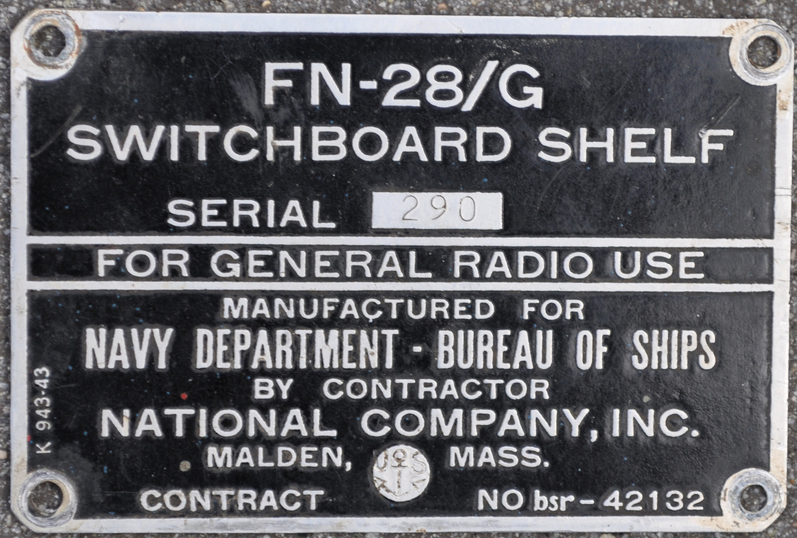
- (1) Switchboard Shelf FN-28/G
1 Set of Spare Parts
0.86
8-3/4 X 10-3/4 X 17-1/8
16
EQUIPMENT SUPPLIED DATA
A B C
3 2 1 Cabinet CY-597/G including:
22-3/8 X 26 X 87-1/2 276
Mounting Strips and appropriate mounting clips
1 1 1 Switch Panel SA-134/G
2-7/8 X 6-31/32 X 20-5/8 10
1 1 2 Conduit end Cover
1 1 - Switch Panel SA-135/G
5-7/32 X 11-3/4 X 19 10.3
1 1 -
Switch Panel SA-137/G 12 X 12-7/32 X 19
25
16 11 - Control C-443/G
5-7/32 X 7 X 7-3/4 5
2 1 1 Jack Panel J-237/G
1-23/32 X
2-1/8 X 19 2.3
3 2 1 Jack Panel J-238/G
3 X 5-7/32 X 19 10.2
3 2 1 Jack Panel J-239/G
1-23/32 X 4-i1/4 X 19 4.9
3 2 1 Jack Panel J-243/G
7 X 8-23/32 X 19 70.3
1 1 - Jack Panel J-265/G
1-23/32 X 2-1/8 X 19 14
6 5 2 Terminal Board Assembly J-242/G
3-15/32 X 4 X 19 2.9
1 1 1 Speaker Assembly Panel LS-139/G
6-1/4 X 8-23/32 X 19 8.9
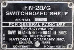
1 1 1 Switch Board Shelf FN-28/G
8-23/32 X 16-3/4 X 22-1/2 45.5
1 1 - Mounting MT-571/G
1-23/32 X 16-7/8 X 19 12.1
6 5 2 Jack Mounting Strip NT-491394
1-23/32 X 3-3/8 X 19 5.8
2 2 1 Patchcord Storage Panel MX-814/G
1-1/4 X 1-23/32 X 19 2
2 2 1 Retainer-Pulley Assembly MX-813/G
2-3/4 X 3- /u X 20-1/4 8.5
5 6 3 Blank Panels Size "A"
3/16 X 1-23/32 X 19 0.6
5 3 2 Blank Panels Size "B"
3/16 X 3-15/32 X 19 1.3
2 2 1 Blank Panels Size "C"
3/16 X 5-7/32 X 19 1.9
2 3 1 Blank Panels Size "0"
3/16 X 6-31/32 X 19 2.5
1 1 1 Blank Panel Size "E"
3/16 X 8-23/32 X 19 3.1
1 1 - Blank Panel Size "F"
3/16 X 10-15/32 X 19 3.7
1 - 1 Blank Panel Size "G"
3/16 X 12-7/32 X 19 4.4
1 - - Blank Panel Size "H"
3/16 X 13-31/32 X 19 5
263 186 77 Connectors NT-49190
20 15 10 Panel Screws #10/32 X
1/2 RH
2 2 2 Code Marker Sets
22 22 11 AF Patchcords installed in MX-814/G NT-491397A
36 in. lg 0.5
1 1 1 Spool #6 lacing twine
12 8 4 Cabinet holding-down bolts (1/2 in. X 3 in. lg bolts)
36 24 12 Clamp Bars each Complete with 3 #10/32 X 1
in. round screws 11-3/4 in. lg
1 - -
Set of equipment Spares 6-1/4 X 10-1/4 X 13-1/4
19
- 1 -
Set of Equipment Spares 6-1/4 X 10-1/4 X
13-1/4 16
- - 1
Set of Equipment Spares 5-1/4 X 7-1/4 X
11-1/8 9
2
2 2 2 Technical Manual NAVSHIPS 91047
GFE
1 1 1 Ohmmeter
ZM-1/U
3-15/32 X 11 X 19
11.9
1 1 1 Multimeter OBQ-4
5-7/32 X 19 X
7-1/2 12
1 1 1 Volume Level Indicator TS-629/U
3-15/32 X 19 X 20
1 1 1 Oscilloscope OBL-3a with:
6-31/32 X 15-1/2 X 19 26.7
Mounting Adapter Kit NT-RL-10625
1 1 - Frequency Meter LR-1
17-1/2 X 19 X 22-3/4
155
- - 1 Frequency Meter
LM-15a with:
8-23/32 X 15-i/2 X 19
123
Mounting Adapter Kit NT-RL-10625
1 - - Radio Receiver RBC Series with:
14-3/4 X 19 X
20-1/8 82
Rack Mounting Cabinet NT-10350
1 - - Power Supply NT-20130 with:
10 X 14 X 19
52
Rectifier Mounting Shelf NT-10348
1 1 1 Set of Electrical Accessories
1 1 1 Set of Tools

 -
-