US Navy Wideband HF Receivers

These receivers have wideband IF outputs that were connected to wideband tape recorders. They were used for intercept and direction-finding operations where gangs of such receivers were used to cover a wide frequency range,

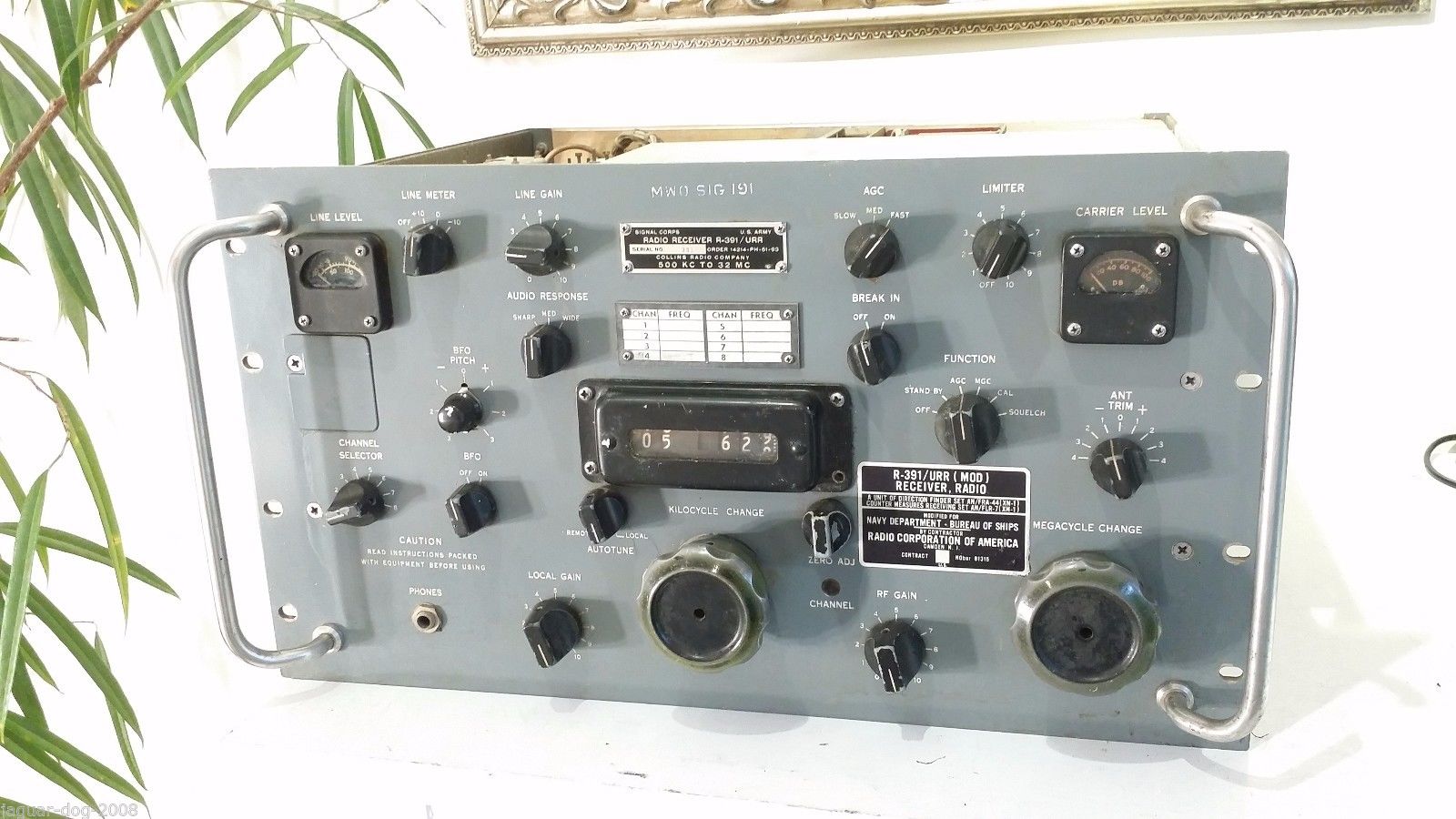
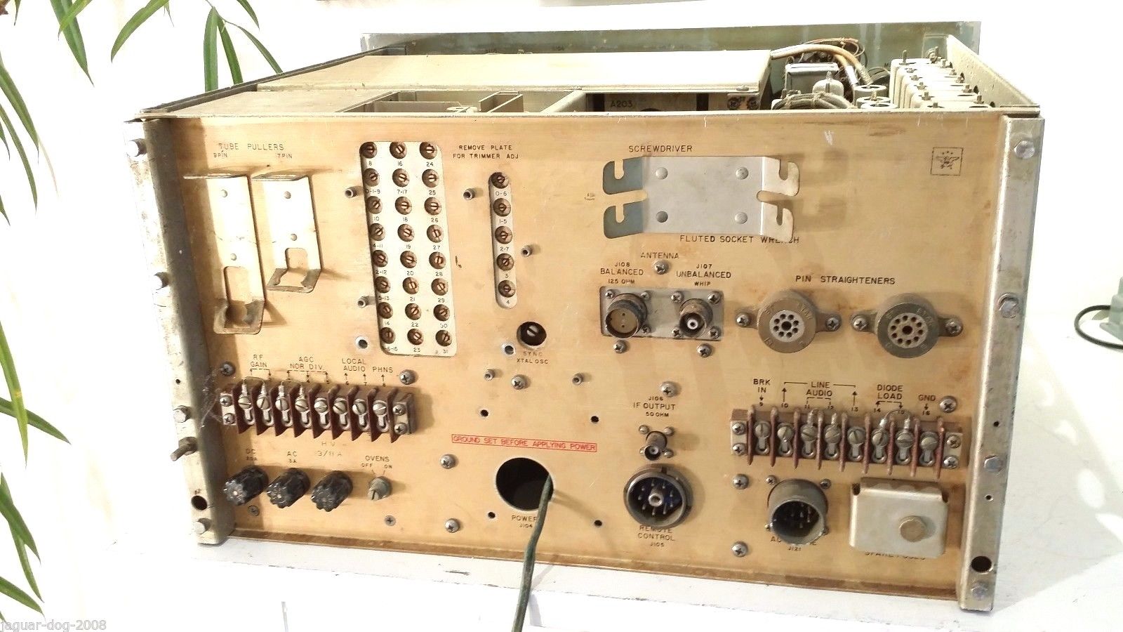
R-391/URR (MOD) for AN/FRA-44 and AN/FLR-7 - note no bandwidth switch 

r391-df-1704-01.jpg (198075 bytes) r391-df-1704-05.jpg (192071 bytes) r391-df-1704-06.jpg (135724 bytes) r391-df-1704-03.jpg (178421 bytes)

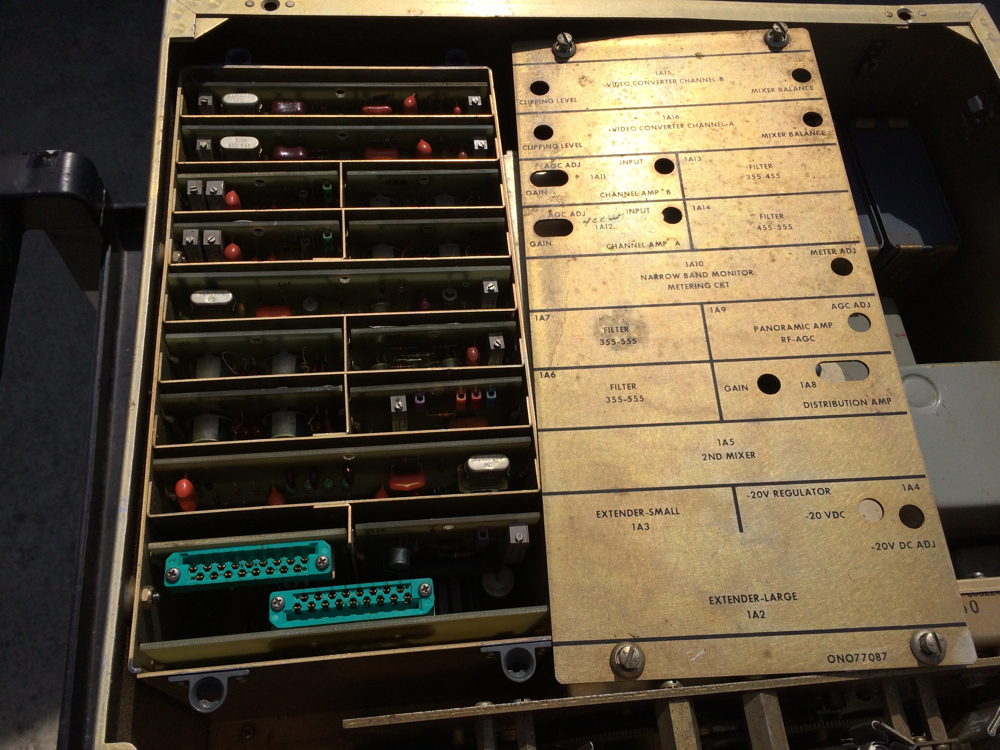
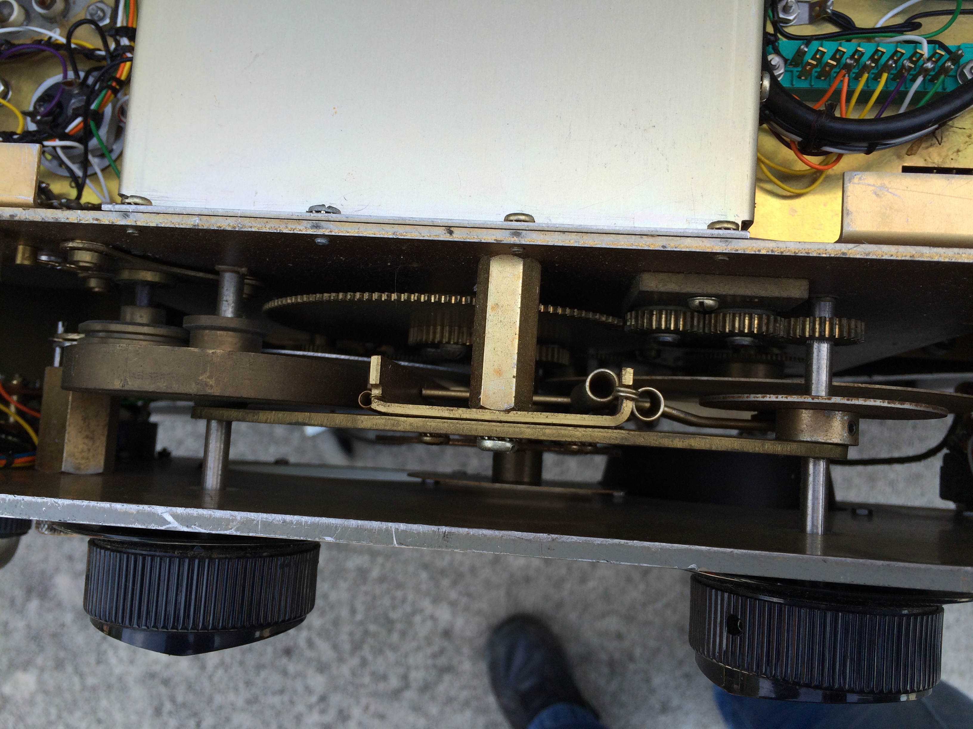
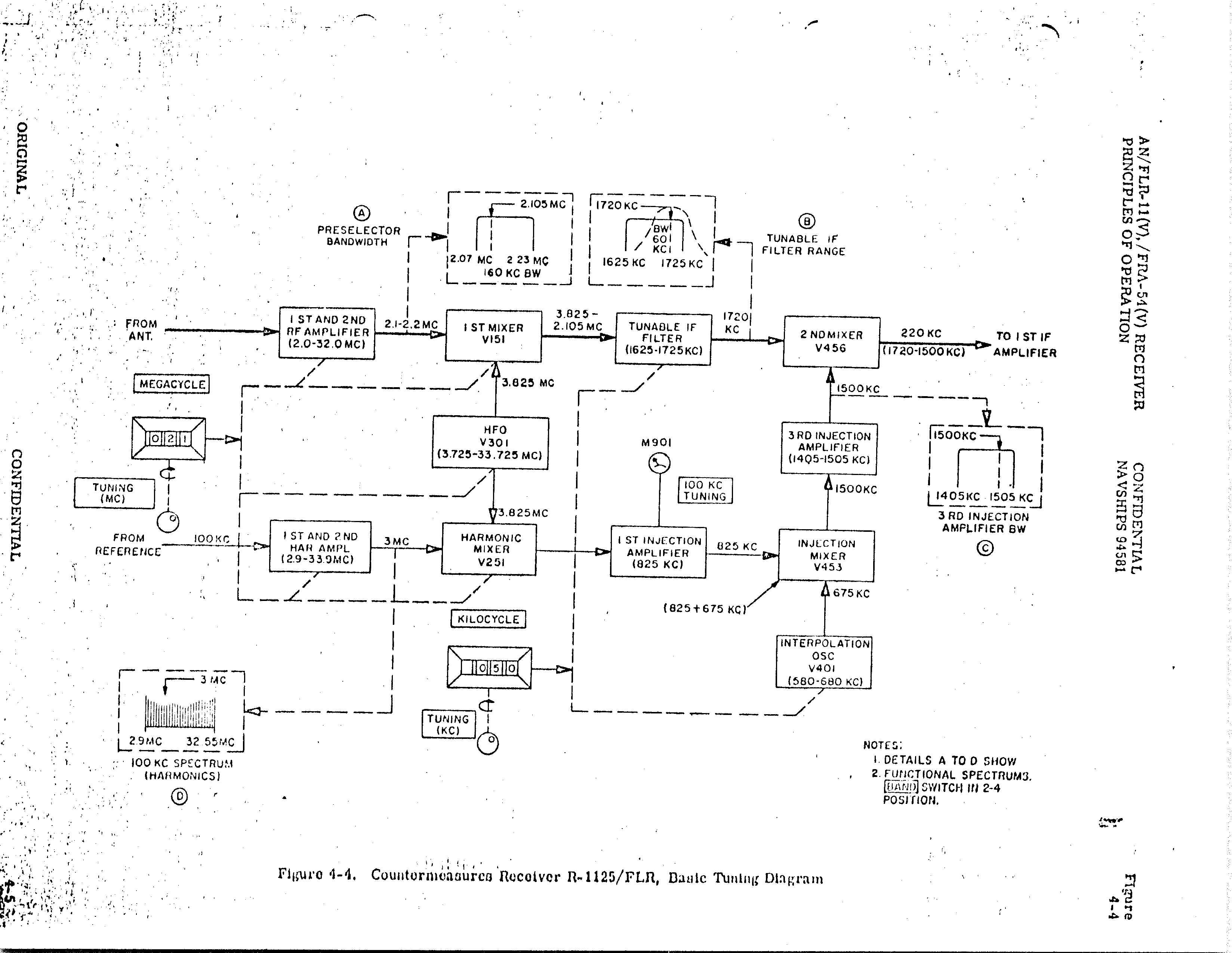
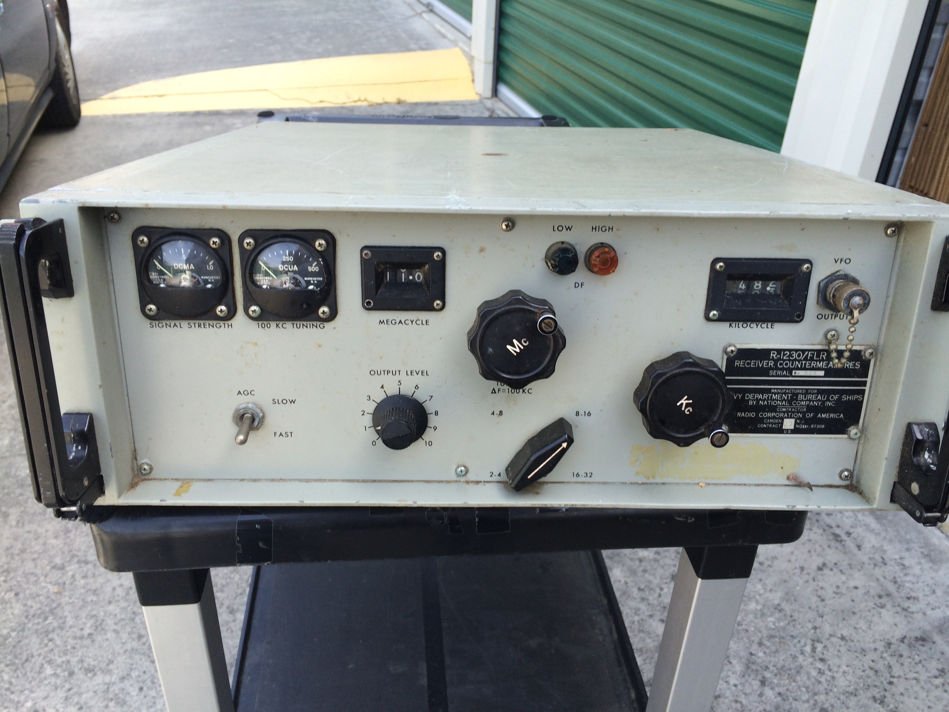
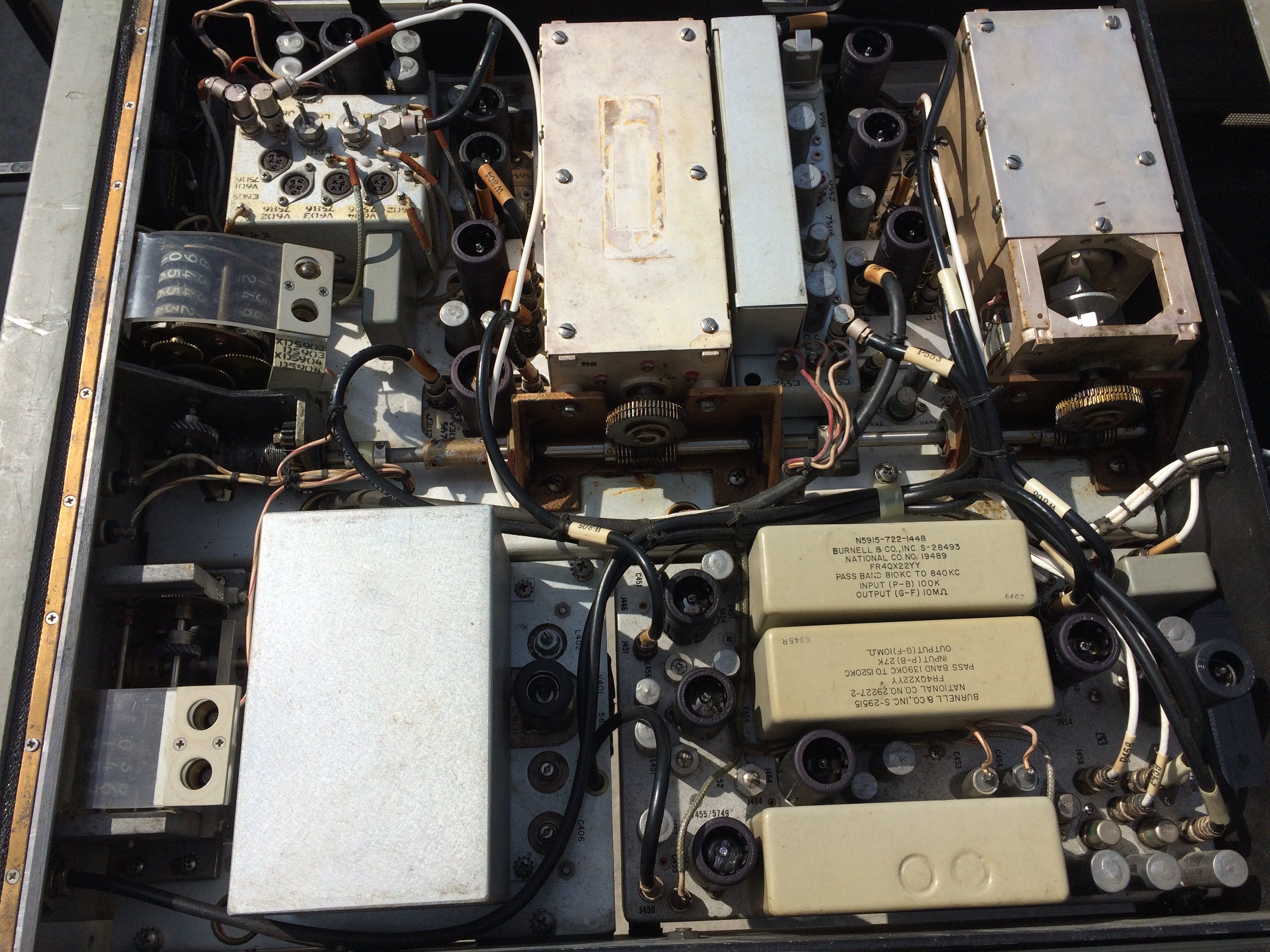
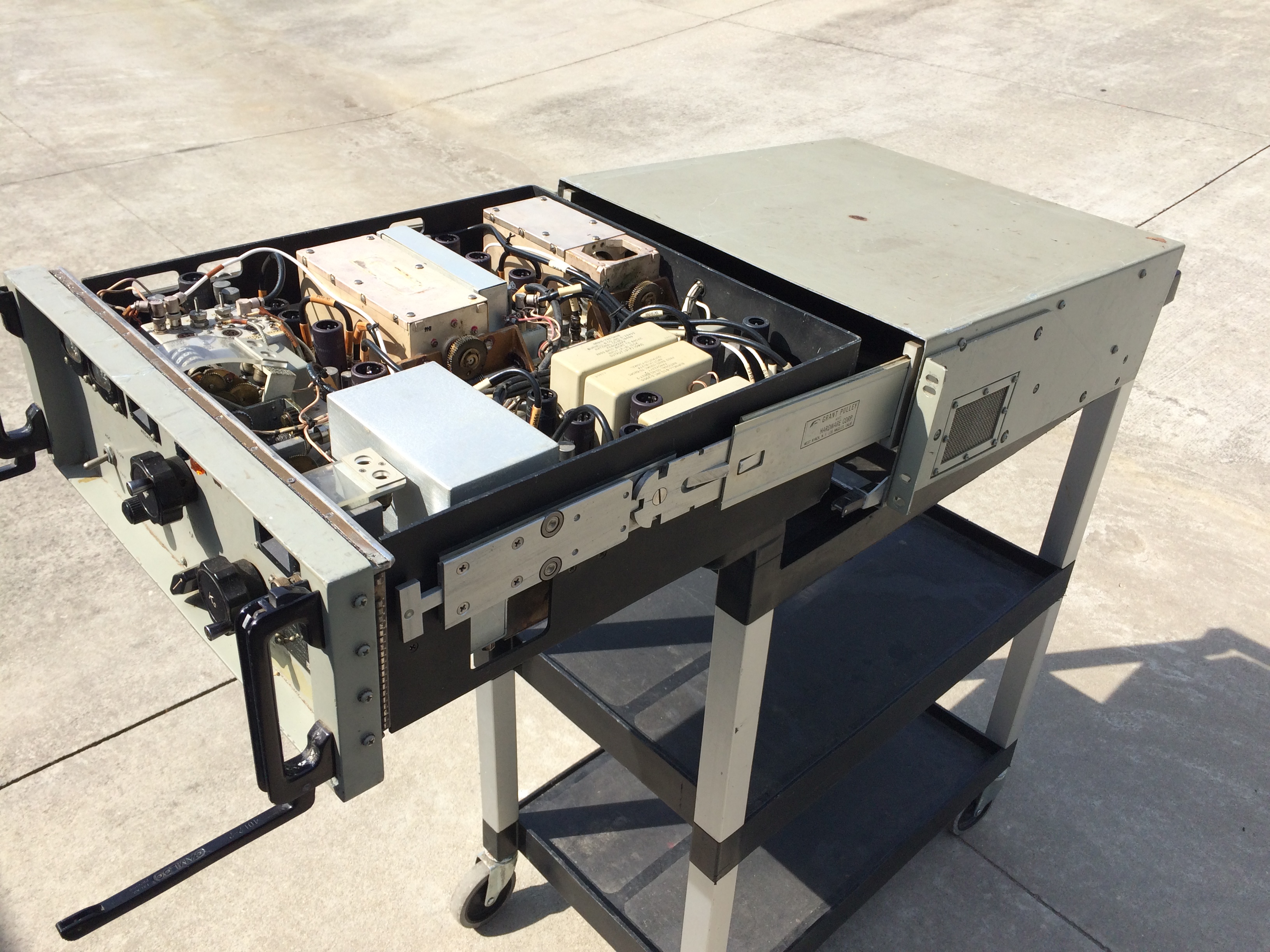
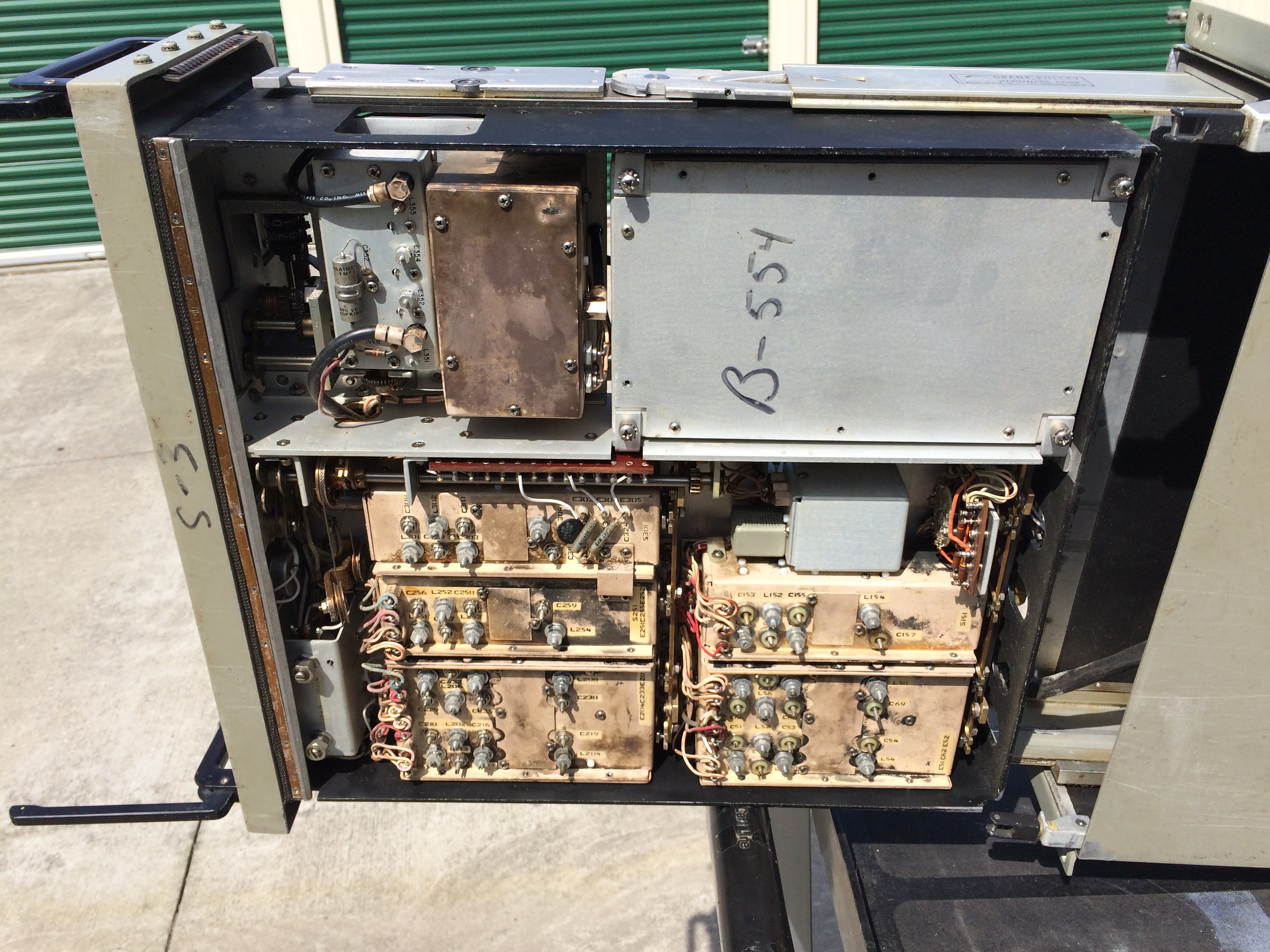
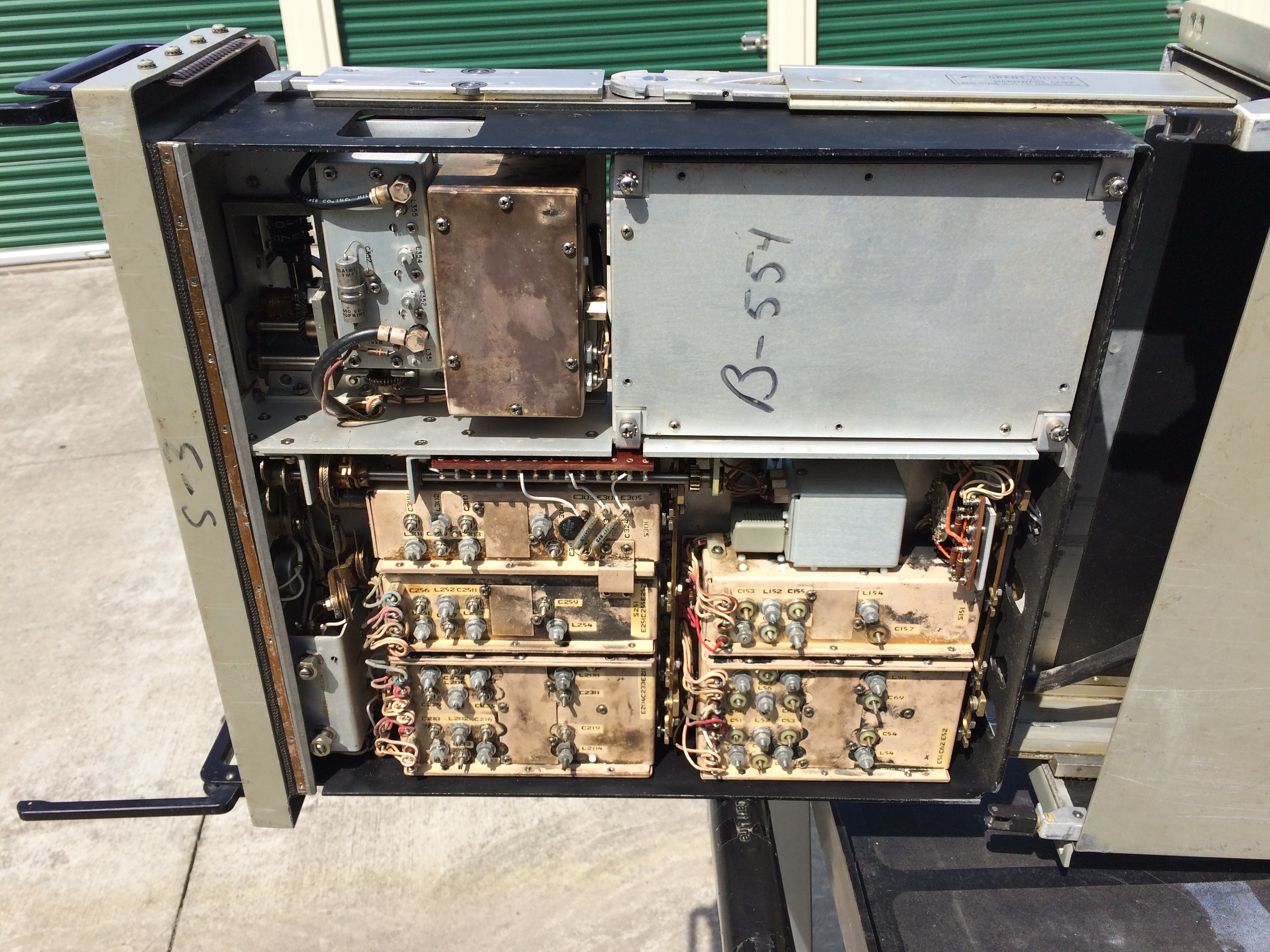
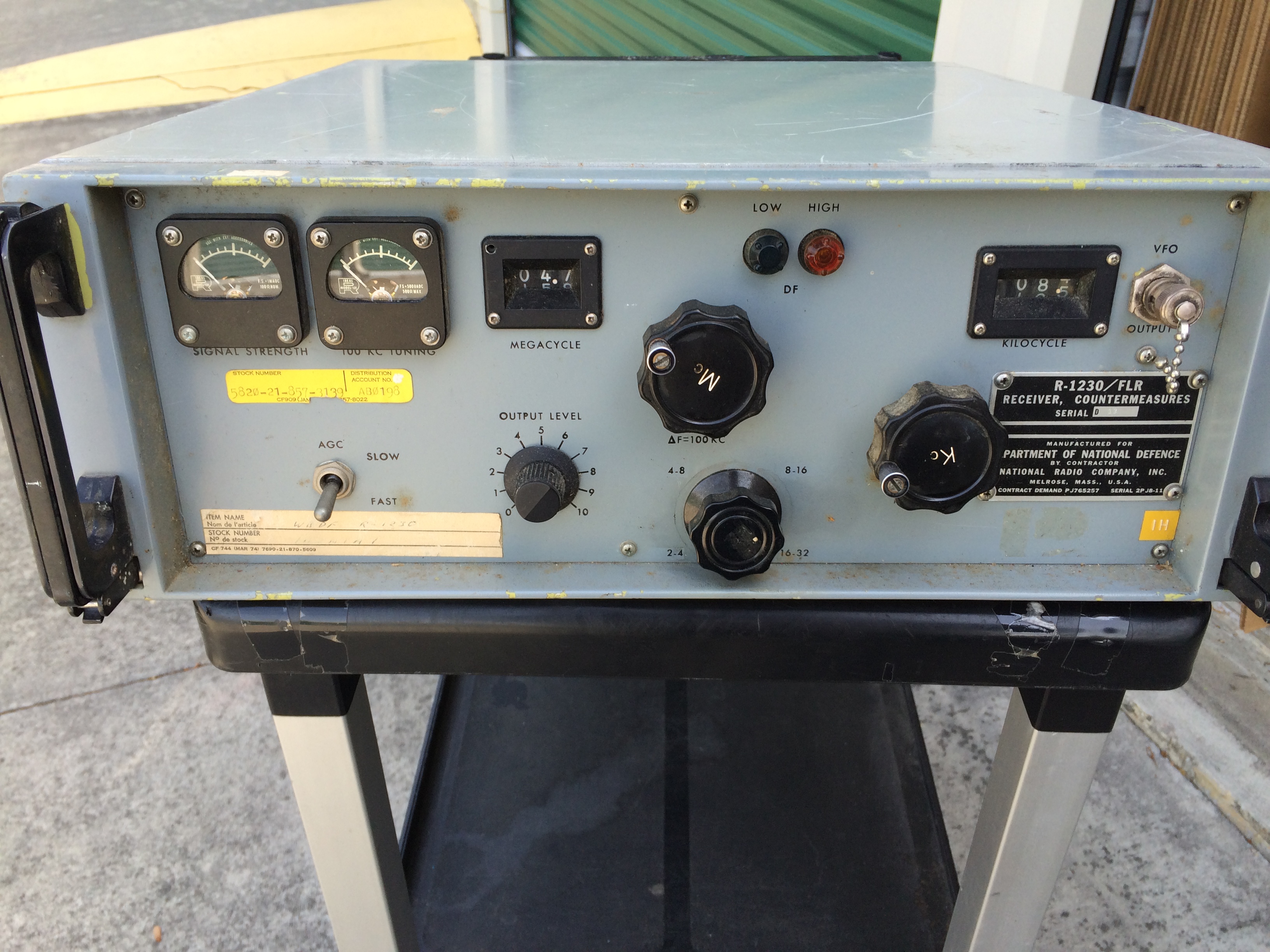
R-1230/FLR - 2-32 mc coverage with 60kc bandwidth output - triple conversion
Used in AN/FLR-11 and AN/FRA-54 systems

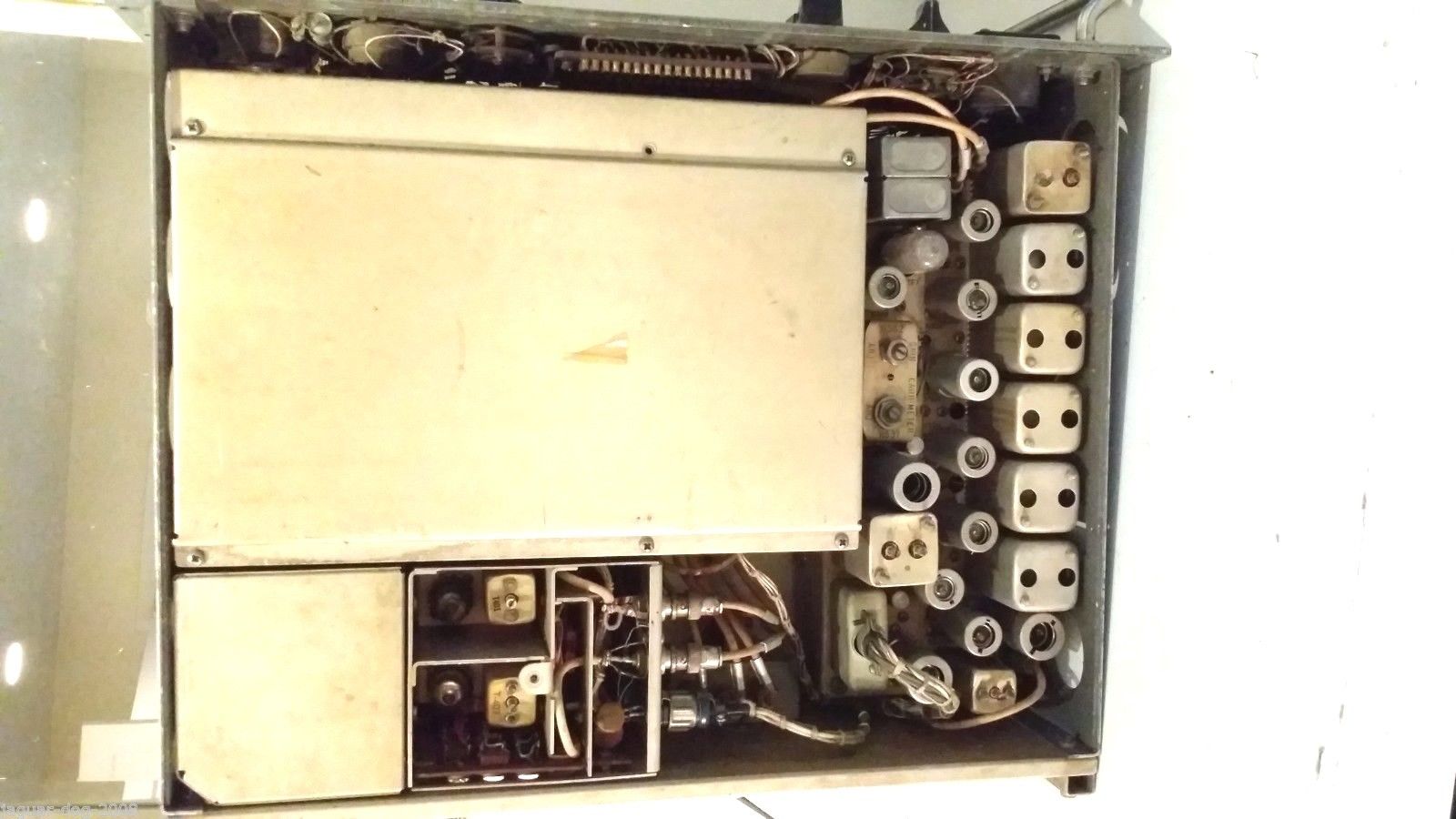
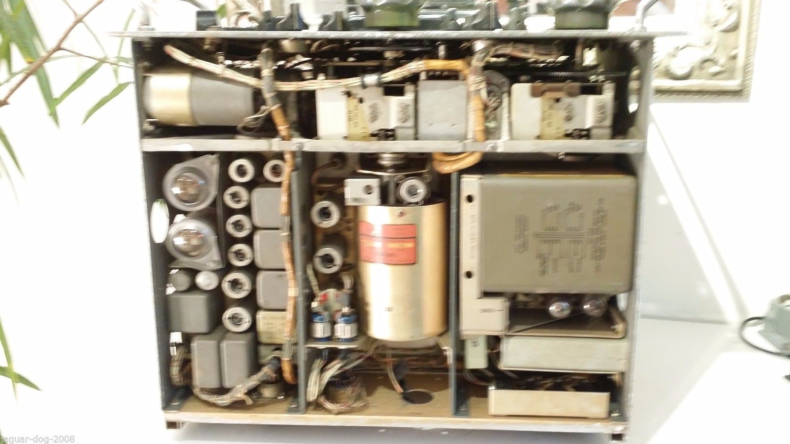
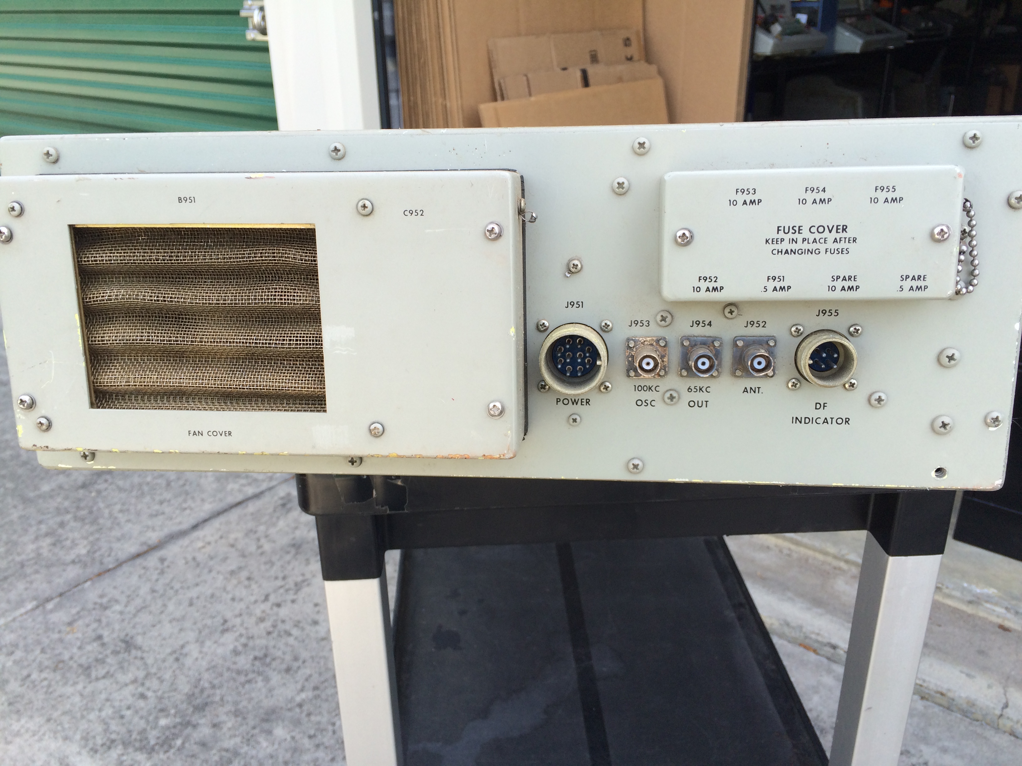
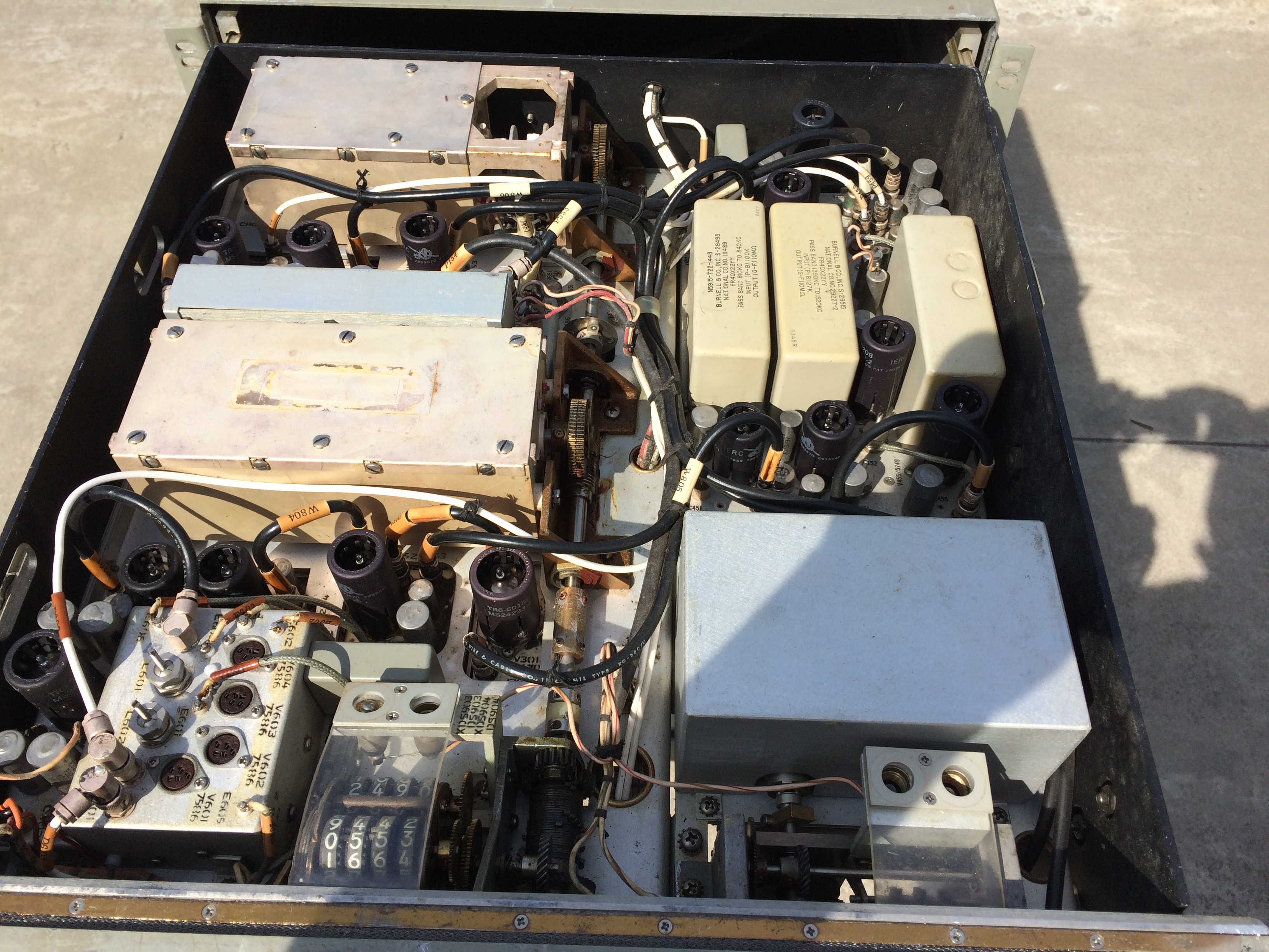
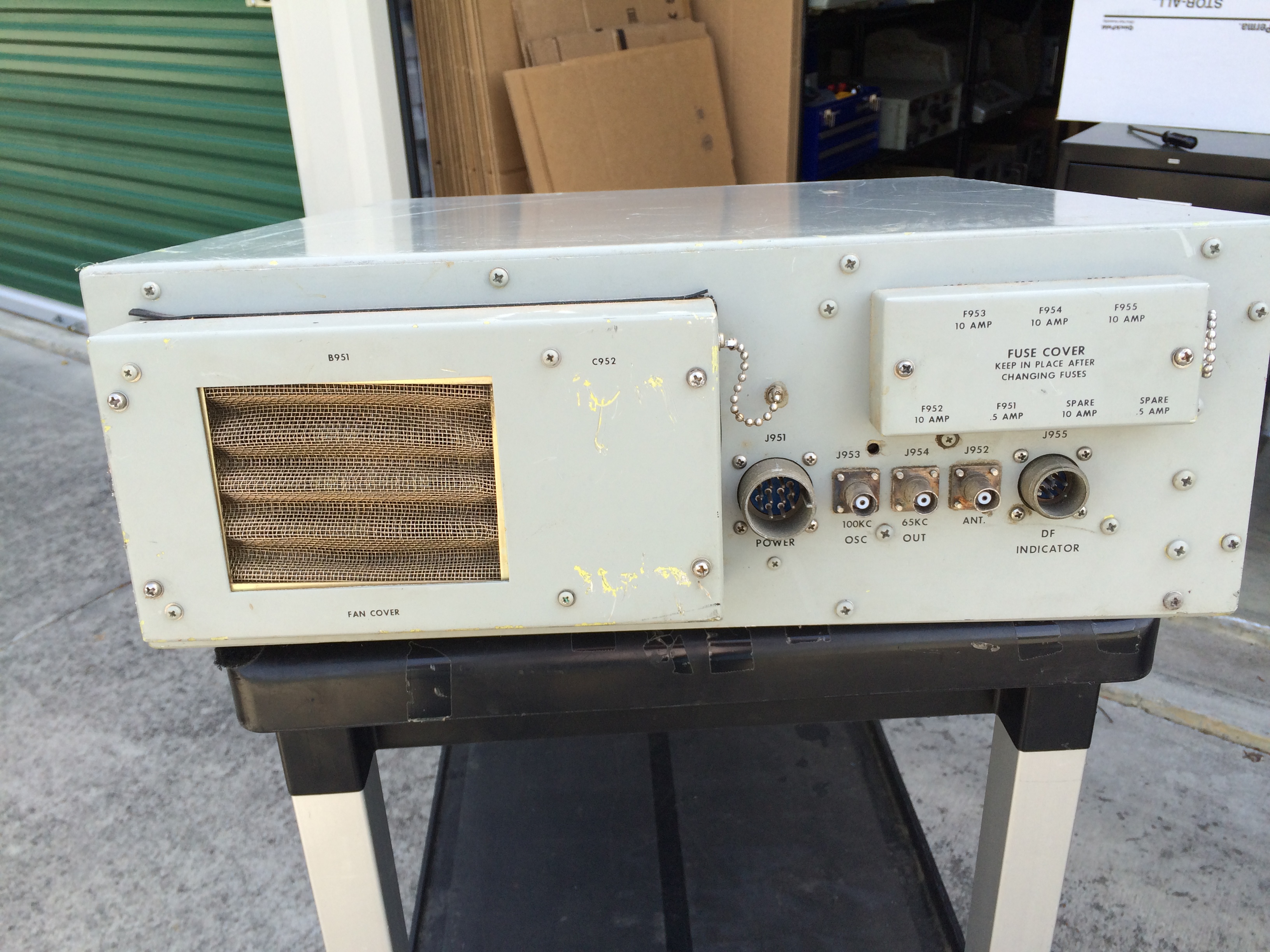
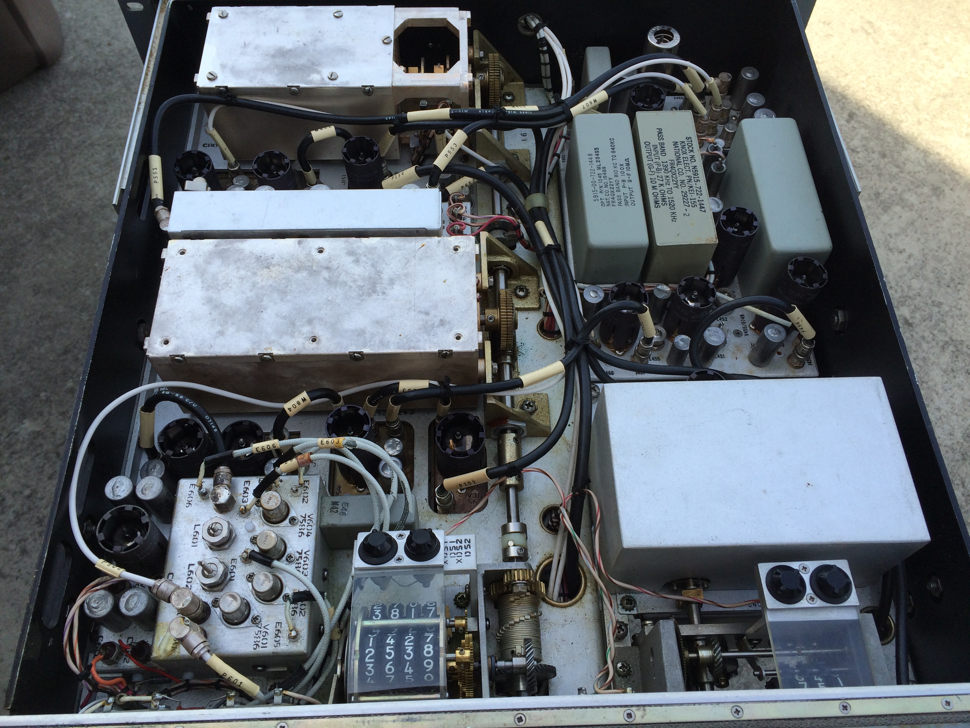
The complete system consisted of two units, one with the RF/IF circuitry and another with the power supply O-928/FLR. The power supply unit was used to power up to 5 RF units and also provides a 100kc reference signal. The power supply section very rarely shows up as surplus. Designed by National Radio. Uses nuvistors as well as miniature tubes. The earlier R-1125/FLR was upgraded to R-1230/FLR via a field change which added a cooling fan.

More photos/info - link
DF/Intercept usage - link
Power supply connections - link
Manual is NAVSHIPS 94581 - poor copy pdf download
           - please send me e-mail if you have an original or a good copy that I could buy or borrow

Countermeasures Receiver R-1125/FLR is a high-frequency, superheterodyne receiver employing triple frequency-conversion for the reception of signals in the frequency range from 2.0 mc to 32.0 mc. It is intended for use in special operating categories and provides a 65 kc output signal having a 60 kc bandwidth. Receiver operation is characterized by extreme frequency stability, permitting long periods of unattended operation. A high level of performance can be expected despite adverse conditions. Initial tuning  is obtained  in 100 kc increments with an interpolation oscillator (in the receiver) which provides continuous tuning between increments. The frequency range is covered in four bands with counter-type tuning dials which permit accurate pre-setting to a desired frequency. A special drift-canceling circuit contributes to the receiver's high performance by canceling any frequency error as the result of frequency drift in the high-frequency oscillator. Drift in the interpolation oscillator circuit is minimal at the low frequency used. 

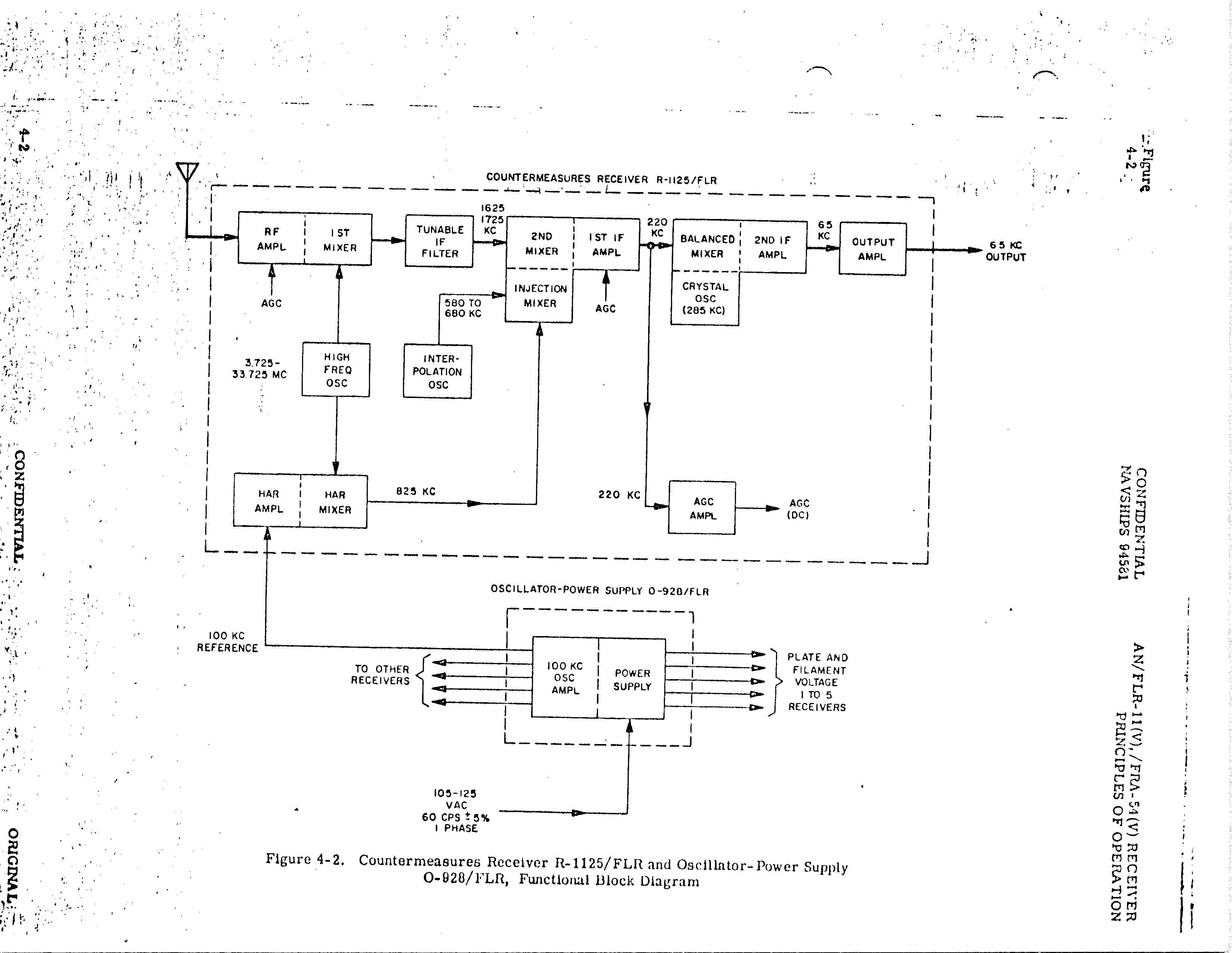
Oscillator- Power Supply O-928/FLR supplies operating power from one to five R-1125/FLR, and includes a 100-kc crystal oscillator which provides a standard reference signal (for incremental tuning) to each receiver.

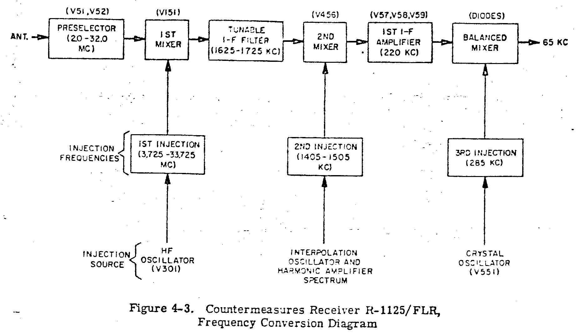
Within the specified frequency range, the R-1125/FLR output is an intermediate frequency band from 35.0 to 95.0 kc which retains all modulation of the received signals with a high degree of fidelity.

Block Diagram
r1125-block-01.jpg (495904 bytes)
Frequency Conversion Diagram
r1125-block-02.jpg (150376 bytes)
Tuning Diagram
r1125-block-03.jpg (572678 bytes)
--
R-1230/FLR with US Navy ID plate
IMG_9608.JPG (1815163 bytes)
IMG_9610.JPG (1850145 bytes) IMG_9611.JPG (2429558 bytes) IMG_9612.JPG (2651187 bytes)
Chassis slides out of the rack-mounted case and also has tilt hinges.
IMG_9613.JPG (2153505 bytes)
IMG_9623.JPG (1944777 bytes) IMG_9622.JPG (2452458 bytes) IMG_9621.JPG (2485200 bytes)
R-1230/FLR with Canadian Dept of National Defence ID plate
IMG_9624.JPG (1937498 bytes)
IMG_9625.JPG (1944013 bytes) IMG_9626.JPG (2564510 bytes) IMG_9627.JPG (2527196 bytes)
==

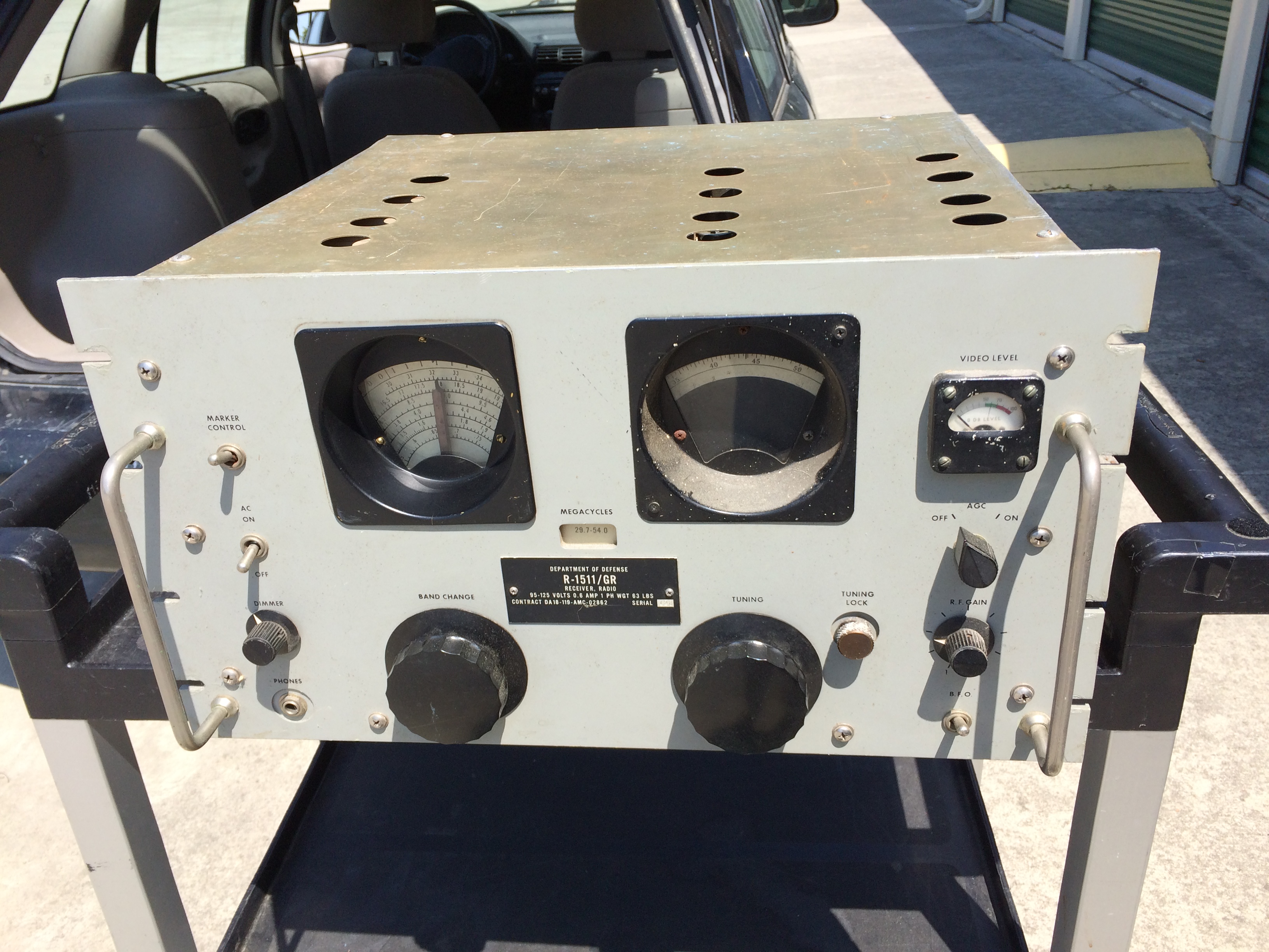
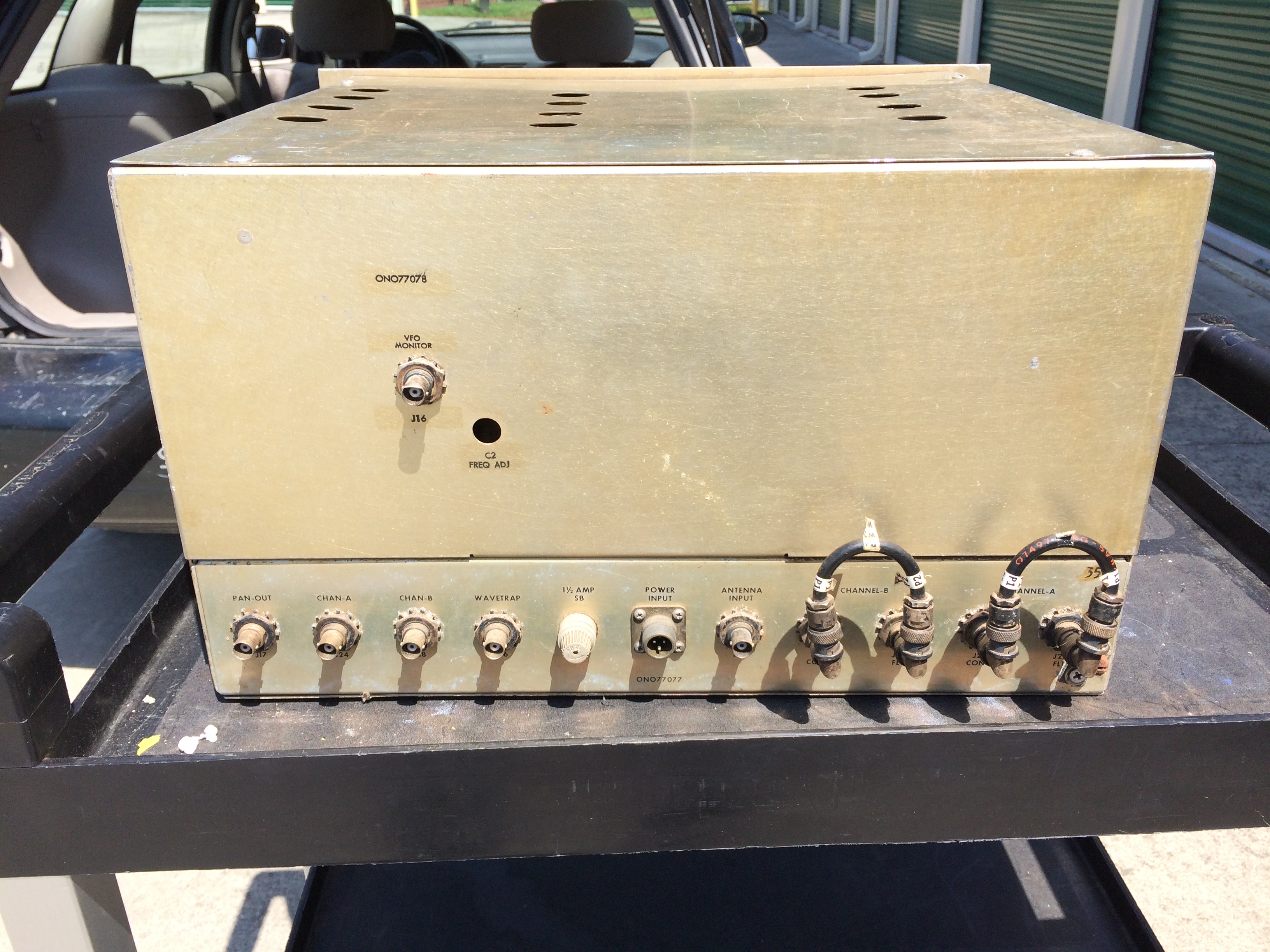
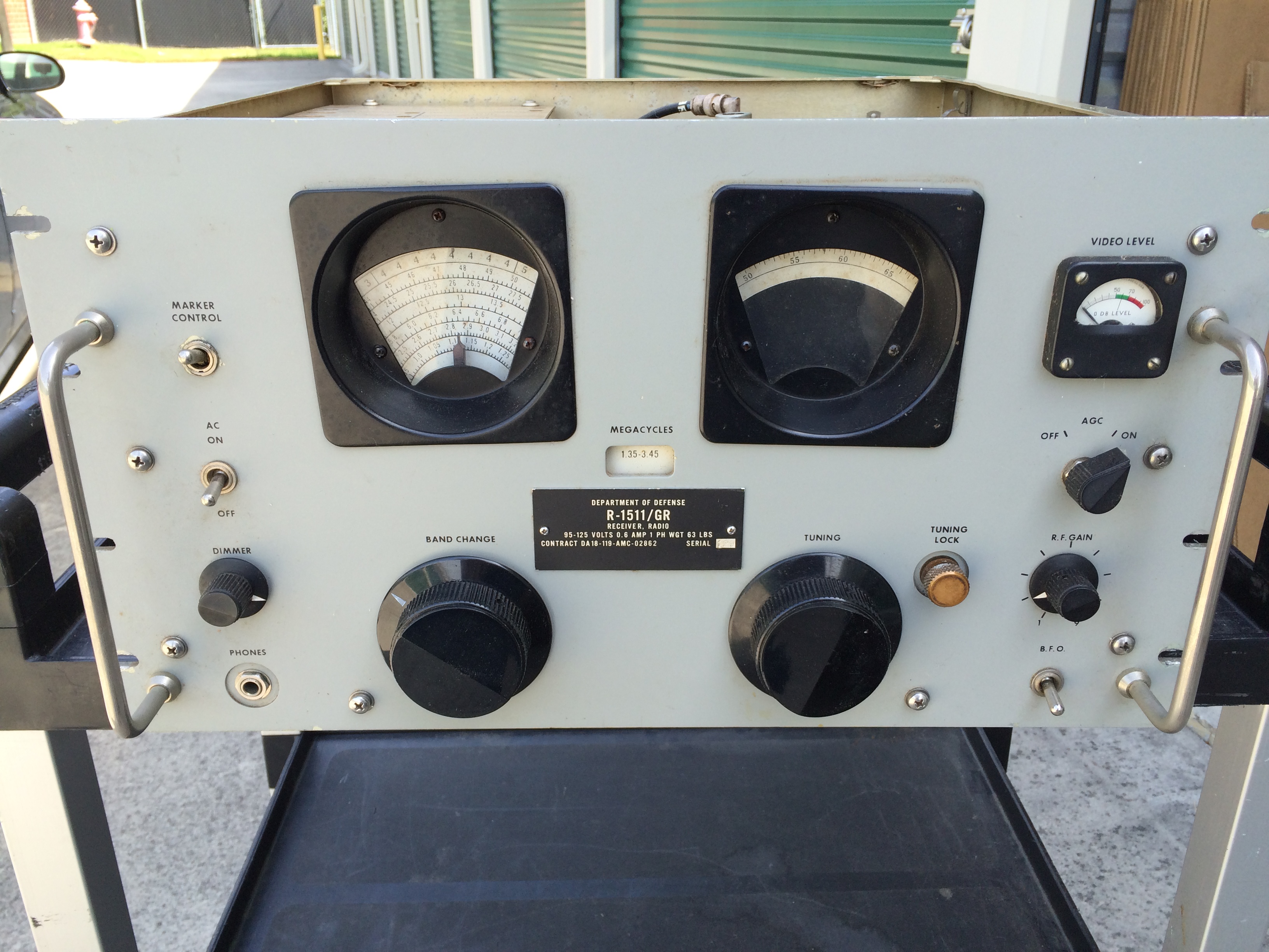
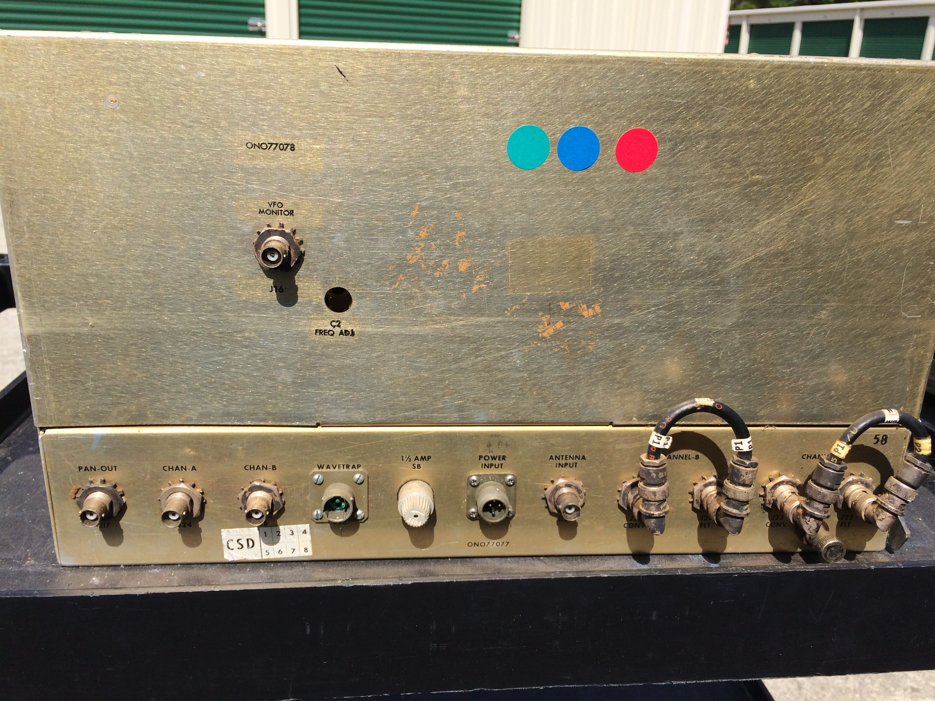
R-1511/GR - 1.35-54mc coverage with 200kc bandwidth output
(also 0.54-1.35mc narrow band coverage)

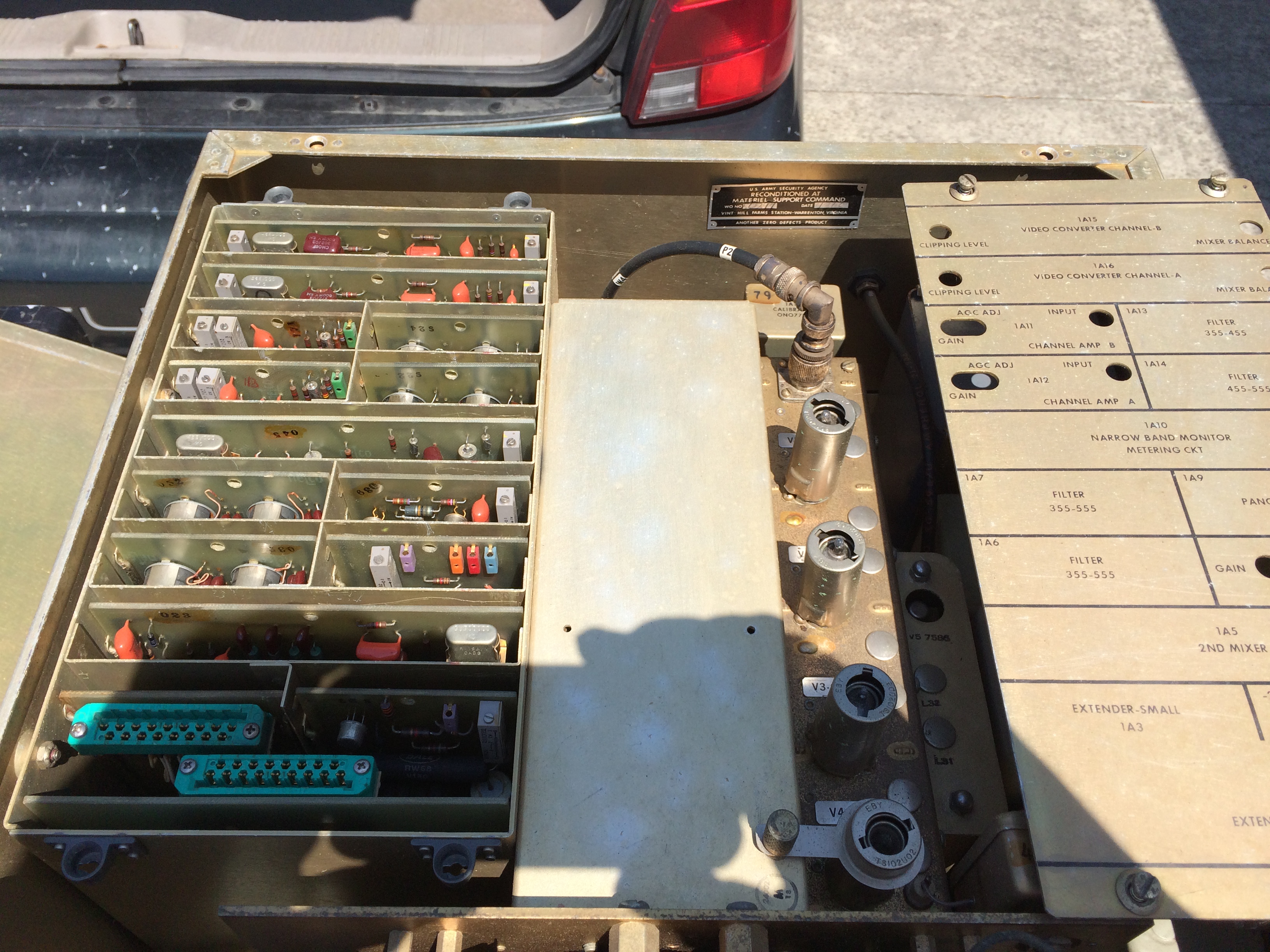
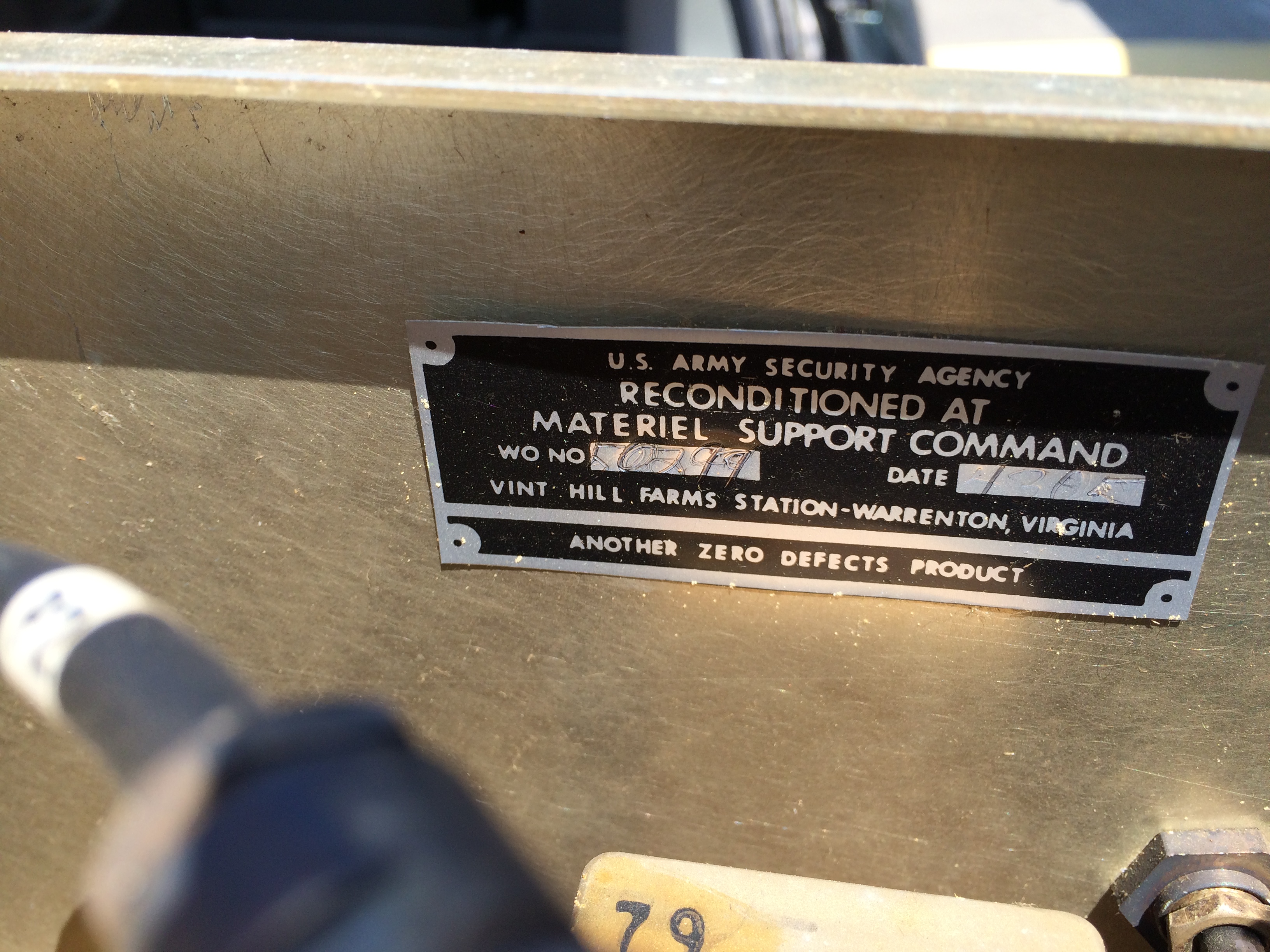
These were used for intercept/DF work much like the R-1230. The ones I have seen have a US Dept of Defense (NSA) ID tag. I think they were primarily used by ASA, but may have also been used at Navy sites.

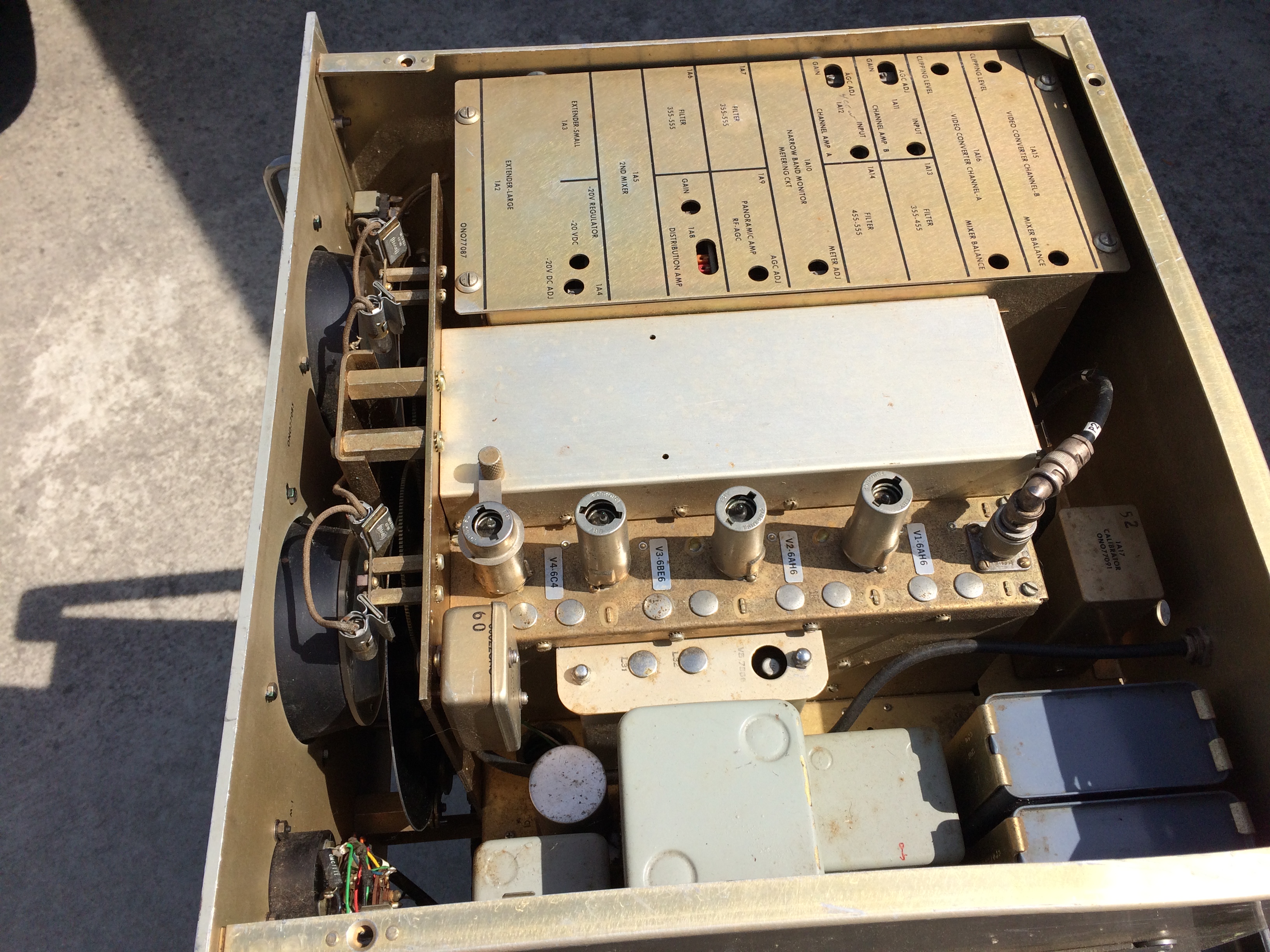
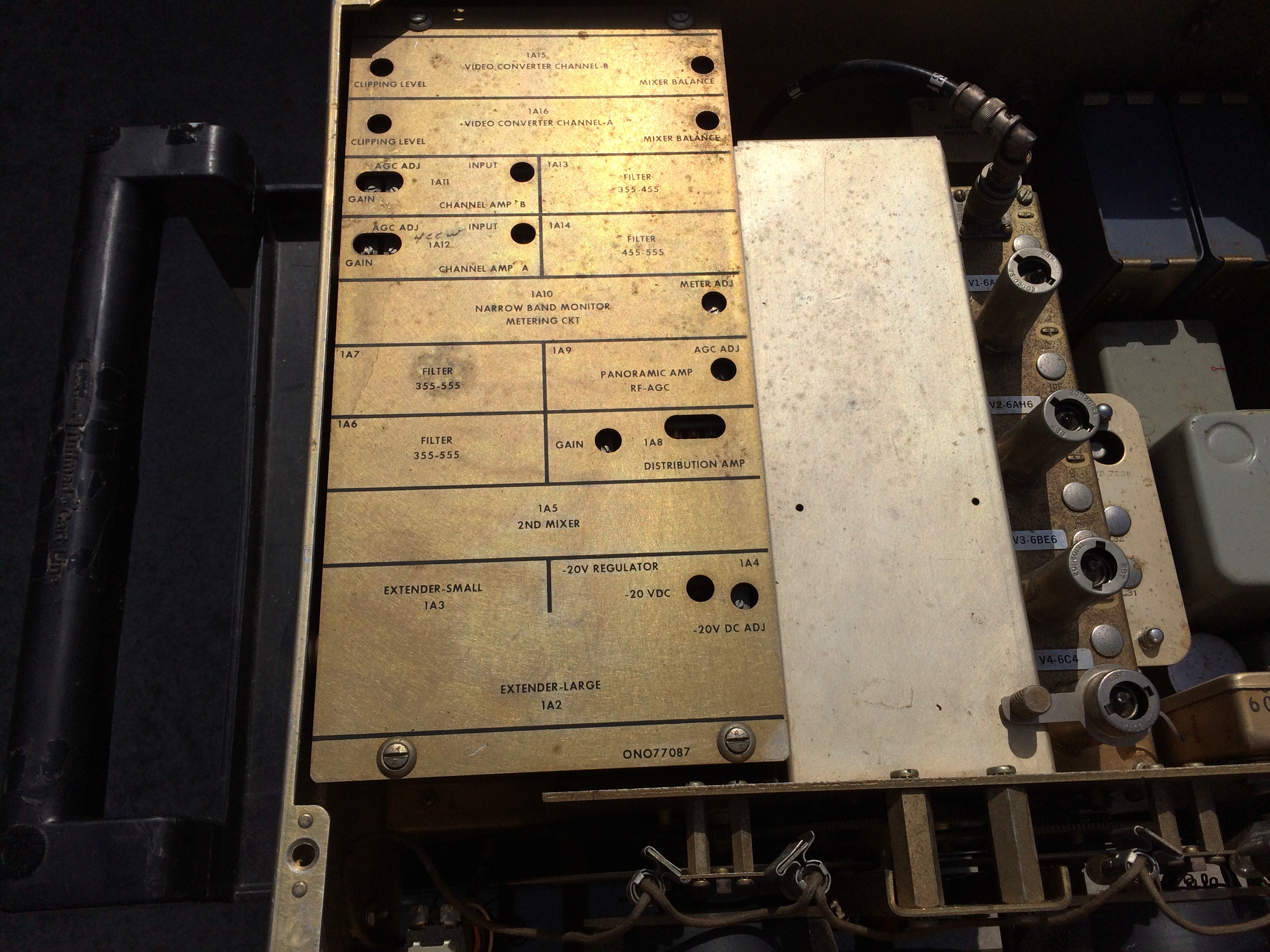
The RF front end is obviously a traditional Hammarlund SP-600 but the IF section is composed of solid state circuit boards.

Manual is NSA TEM-0541-01-0A - pdf download

r1511-block.jpg (519783 bytes)
Serial #128
IMG_9653.JPG (2001325 bytes)
IMG_9645.JPG (2301619 bytes) IMG_9646.JPG (2193419 bytes) IMG_9654.JPG (2328753 bytes)
with PC board cover removed
IMG_9656.JPG (2416786 bytes)
Reconditioned by ASA at Vint Hill Farms Station

IMG_9655.JPG (2244568 bytes)

Bottom cover removed
IMG_9657.JPG (2614604 bytes)
--
Serial #129 (no top/bottom covers)
IMG_9628.JPG (1821534 bytes)
IMG_9631.JPG (2991343 bytes) IMG_9629.JPG (2448960 bytes) IMG_9630.JPG (2597501 bytes)
with PC board cover removed
IMG_9632.JPG (2589832 bytes)
IMG_9633.JPG (2501477 bytes) IMG_9634.JPG (2214501 bytes) --

See also the AN/FRD-10 CDAA page

During the 1950s and 1960s, NRL demonstrated technology that permitted a radical improvement in the performance of high-frequency direction finding (HFDF) networks and oversaw the deployment of this technology in Project Boresight and Project Bulls Eye.

The first of three innovations that underlay this work was retrospective direction finding. Previously, all stations in an HFDF network were required to measure characteristics of the same signal while transmission was still occurring; after-the-fact measurements were needed. Previous attempts at NRL and elsewhere were limited by storage bandwidth and recorder instabilities. Recording significant fractions of the HF spectrum and using a digital method for overcoming recorder instabilities enabled retrospective DF. This was the basis of the 1960 quick-reaction Project Boresight that deployed the AN/FLR-7 and AN/FRA-44 worldwide.

The second innovation was the use of circularly disposed wide-aperture direction finding arrays, which significantly increased HFDF location accuracy and signal collection. In the 1950s, NRL constructed a 400-ft diameter electronically steerable array and perfected the underlying technology. During Project Bulls Eye, scaled-up versions of this prototype were deployed worldwide by the Navy as the AN/FRD-10.

The third innovation was the use of computers for control of the HFDF network and for the prompt triangulation of target locations. To achieve high computer reliability in the pre-integrated-circuit era, a novel architecture of closely coupled shared-memory multiprocessors was reduced to practice and was deployed as the AN/GYK-3.

Project Boresight’s crucial contribution to national defense was recognized by the awarding of the Distinguished Civilian Service Award to NRL’s R.D. Misner and M.J. Sheets. The more ambitious Project Bulls Eye deployed the second and third innovations and improved the first with the AN/FRA-54 and the AN/FSH-6, thereby making HFDF a principal means of global ocean surveillance, with special capabilities against critical targets.