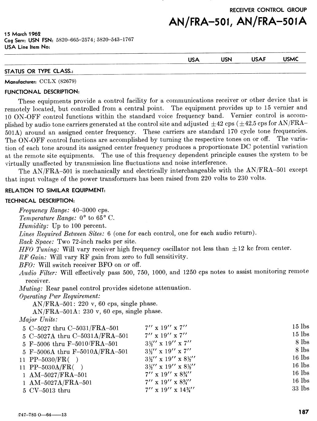
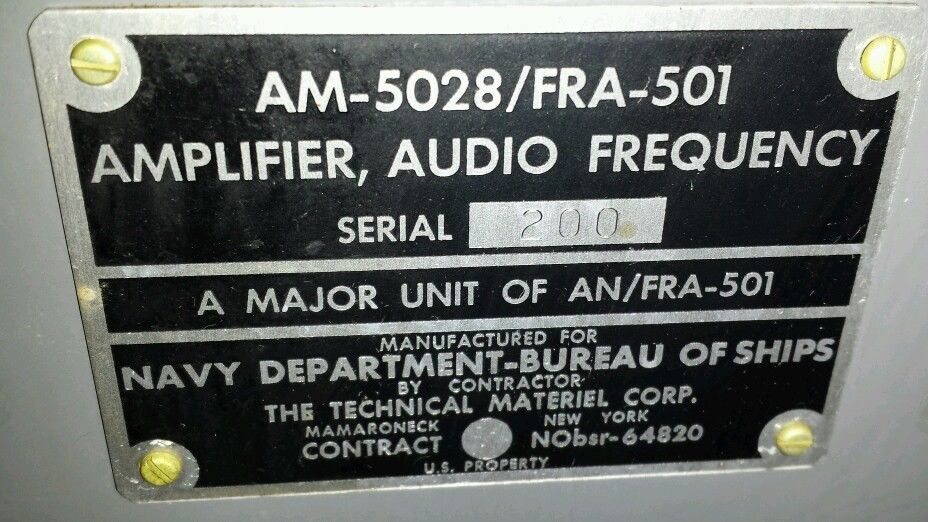
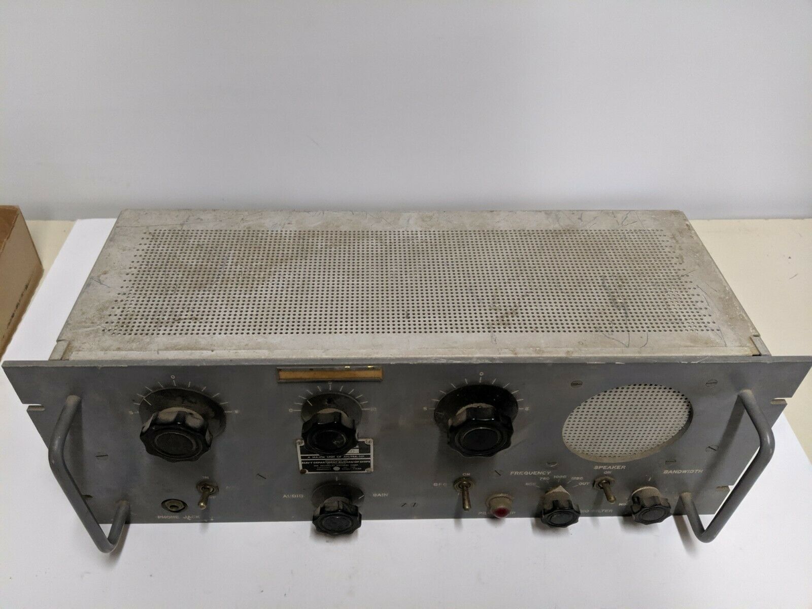
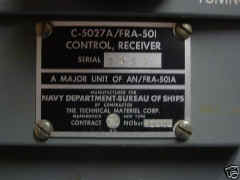
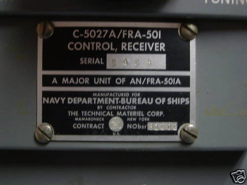
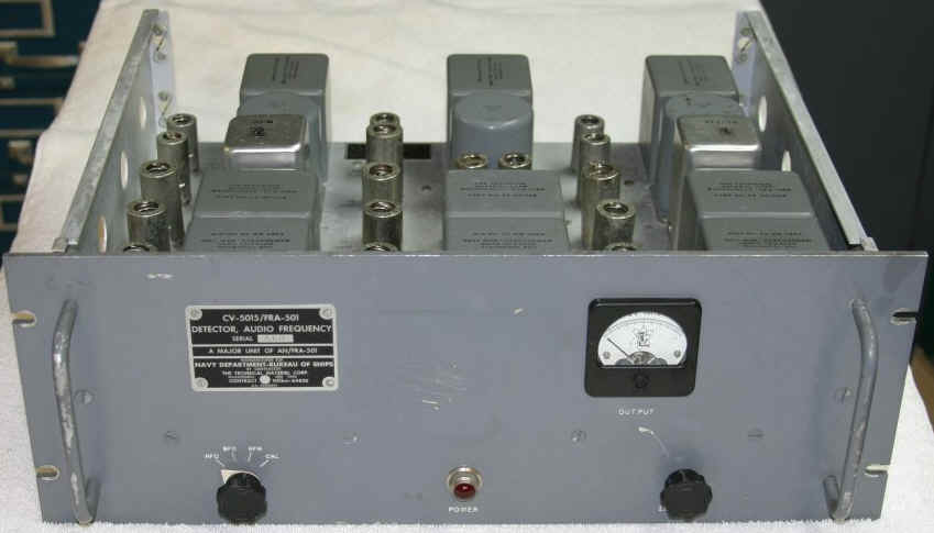
AN/FRA-501, AN/FRA-501A, AN/FRA-19(V) Receiver Remote Control
Remote control for AN/FRR-49 and AN/FRR-502 - allows
control of HF osc, BFO, RF gain, BFO on-off, AGC on-off
Remote Receiver - Long Range Ship-Shore and Air-Ground Service
BuShips Journal June 1957
By Lester G. Douglas
Receiver Systems Section, Bureau of Ships
Communication offices in industrial centers, such as shipyards and administration
areas at air stations, are usually heavy with interference generated by
electrical, electronic, and mechanical equipments. This condition makes radio reception
with equipments and associated antennas in the immediate vicinity extremely difficult.
Expeditious, accurate, and dependable communications are a primary need for carrying out the
military mission. Considerable study and analysis has been given the radio interference
problem, and many remedial actions have been recommended. Although the studies have resulted in improvement, interference
still remains a major problem
This article describes equipment and a system recommended by the Bureau of Ships for reducing interference
in communications received in, but not limited to, administrative areas of shipyards and
air stations. The equipment, AN/FRA-501 and AN/FRR-502, was approved for service
use by the Chief of Naval Operations in April 1956.
The full significance of "interference" cannot be comprehended without knowing the kinds of
equipments that cause interference. The list includes such common equipment as- Electric calculating machines,
mercury arc rectifiers, flashing signs, electric typewriters, ignition systems, buzzers, vehicle
regulators, relays, switches, telephone dials, teletypewriters, thermostatic controls, traffic signals, electric
motors, magnetos. Also, defective lamp sockets, defective switching and wiring, high
frequency equipment such as diathermy, neon signs, swinging grounds, electric razors, vibrators,
power lines, poor ground (sparking), shot effect, thermal agitation, generators,
arc welders, loose fuses, fluorescent lights.
This list is by no means complete. To relax the tremendous task of reducing interference of the
individual offenders to acceptable levels and still have reliable radio communications, sensitive radio
equipment should be installed in well-protected, noise-free areas. This precaution is
usually followed whenever possible.
However, when other than remote controlled receivers are installed at locations removed from noisy
administrative areas, an operator must be at the equipment position to tune in the signals properly,
copy the messages, and then relay them to the administrative area communications center. The use of
the AN/FRA501 and AN/FRR-502 equipment eliminates the need for an operator at the signal-receiving
site and saves the time lost in relaying the message.

Remote Tuning
Complete remote tuning of all necessary receiver functions becomes a very complex problem, especially
when functional controls must be transmitted over telephone landline or microwave (radio) link.
Therefore, early in the development of the AN/FRA-501 and AN/FRR-502 equipment, the Bureau of
Ships decided that, far the time being, only those functions necessary for fixed-frequency application
would be provided. The decision greatly simplified the task of development, with consequent
reduction in cost to a practical figure.
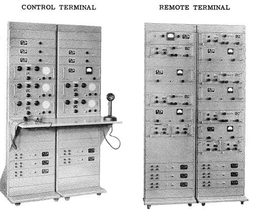
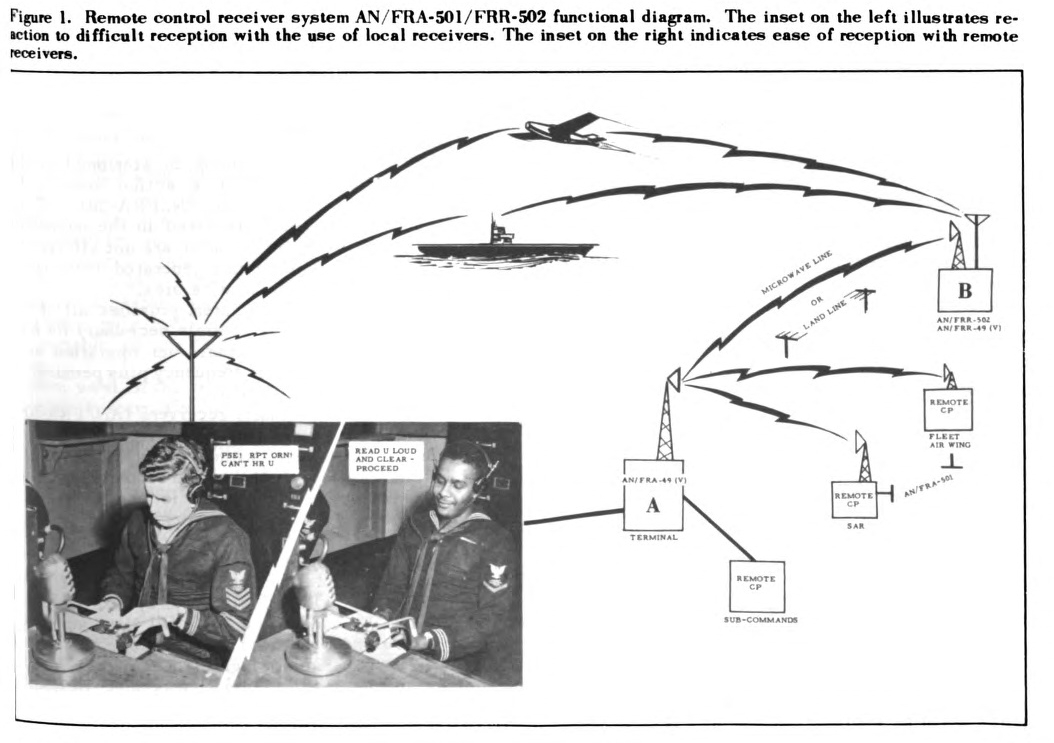
In the system evolved (figure 1), the receivers (AN/FRR-502) with their associated antennas are installed in remote
noise-free areas, and the necessary operator for proper tuning is stationed in
the administrative action area at the control unit (AN/FRA-501). Thus signals received in the
noise-free remote location are not affected by interference generated at the
noisy administrative area.
The system provides all of the normal controls necessary for non-clear channel net operation on
a specific frequency plus permissible signal drift.
Remote receivers (AN/FRR-502) have functioned for as long as 2 weeks without attention,
but a daily system check is recommended. Additional periodic checks to
meet local conditions should be made when recommended by the technical maintenance
authority.
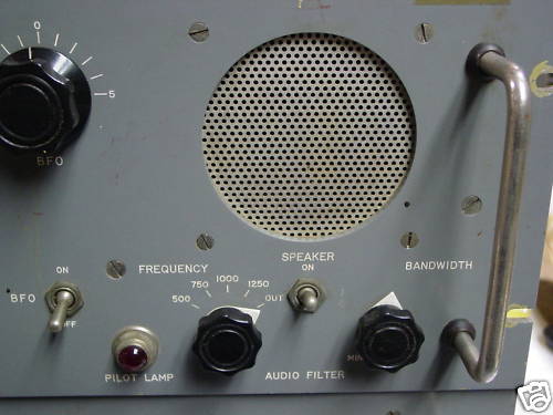
The receiver component (AN/FRR-502) of the system has been designed to fulfill
the long existing need for a sturdy, easily tunable, single frequency receiver
that will provide maximum flexibility and give thoroughly dependable, unattended continuous reception
of AM radio, telephone, CW (continuous wave) telegraph or teletype, and MCW (modulated
continuous wave) teletype and single side band signals.
The design of the AN/FRR-502 is a departure from the conventional single channel receiver in that it
provides for both crystal and variable frequency oscillator operation of the
high frequency oscillator and the beat frequency oscillator.
The front end of the receiver is simply and accurately tuned by a single frequency tuning dial with
a vernier reduction ratio of 10 to 1. The tuning dial gives maximum traverse speed and ease of
operation. A specially designed input transformer provides an impedance matching circuit suitable for use
with 75-ohm unbalanced line or 300-ohm balanced line.
Frequency Range
The AN/FRR-502 covers a frequency range of 2 to 32 megacycles by means of four plug-in tuning
drawers that contain the necessary coils to cover the frequency range. The drawers are sturdily built and
incorporate the first RF, second RF, VFO, and mixer circuits. This type of
construction provides excellent shielding between stages and minimizes the difficulties
usually found with this type of receiver.
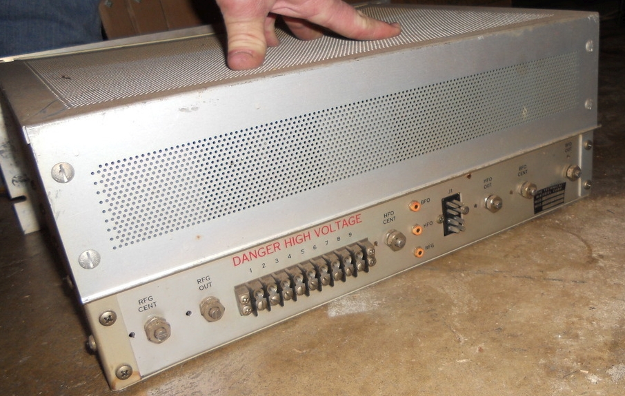
Remote control facilities have been provided for on the rear of the receiver so that the high-frequency
oscillator, the beat frequency oscillator, and the radio frequency gain may be controlled
by variable direct current potentials.
When used in the remote control receiver system, the high-frequency oscillator, the beat frequency
oscillator, and sensitivity are controlled by means of audio tone carriers generated at the control
site. In addition, on/off control of the AVC and BFO are provided for. This feature is particularly
useful when the receiver is to be used remotely for CW and telephone operation.
This remote control provides approximately plus or minus 2.5-kilocycle and 1.5-kilocycle adjustment
of the high-frequency oscillator from the preset frequency of 5 megacycles and 10 megacycles, respectively,
and a plus or minus 2-kilocycle range of the beat frequency oscillator.
Although the receiver is controlled by direct current, it is impractical to transmit direct
current signals over rather long distances, and an alternate method is used.

Control signals are generated as tones in the frequency range of from 425 to 2805 cycles a second
and transmitted via land lines or microwave radio to the receiving site where the tones are separated
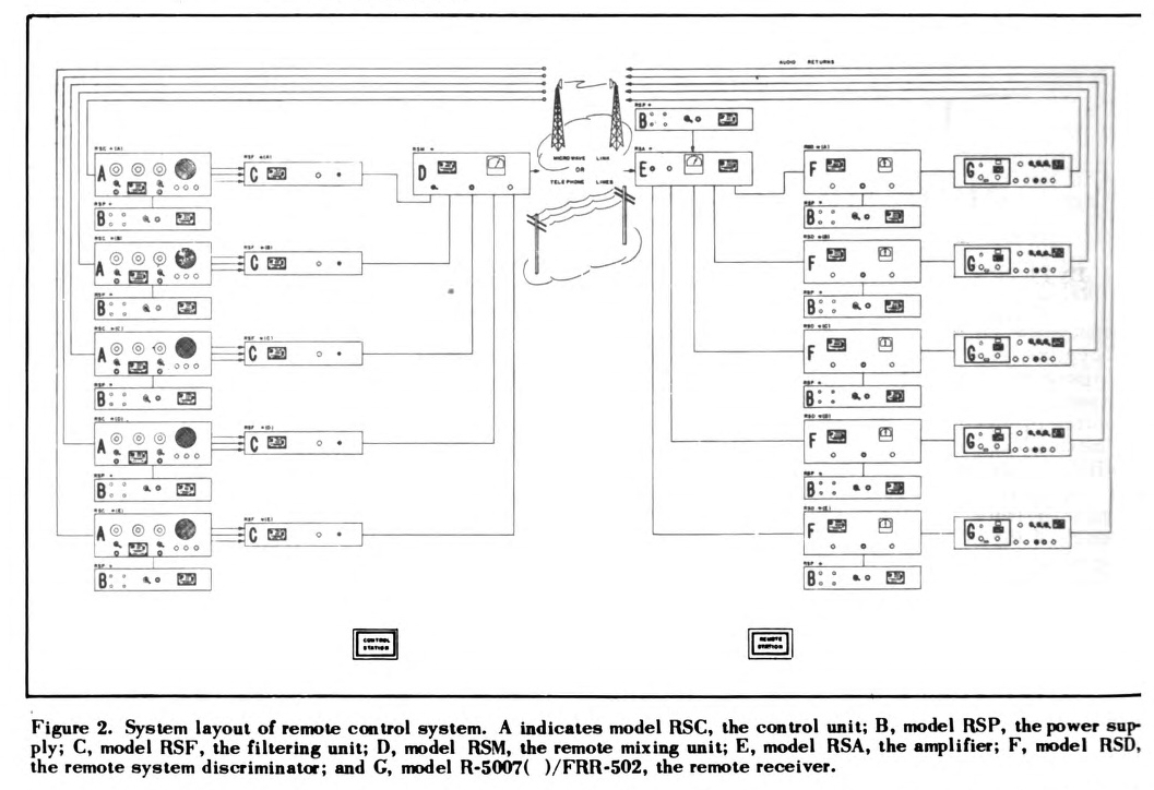
and rectified (converted to direct current). The components required (shown in figure 2)
are-
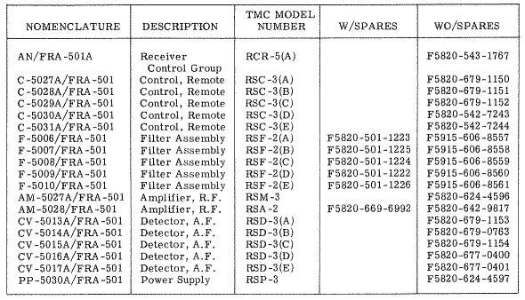
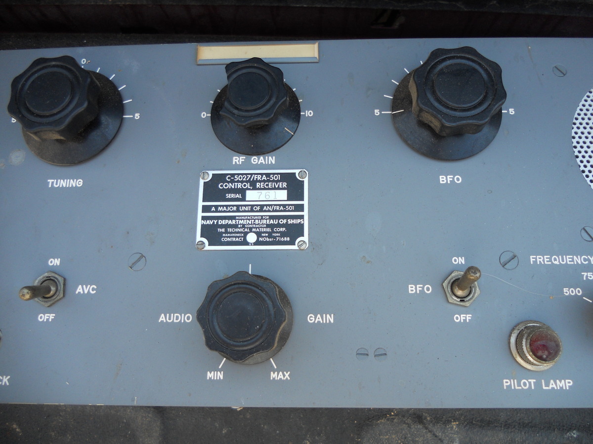
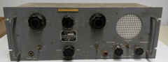
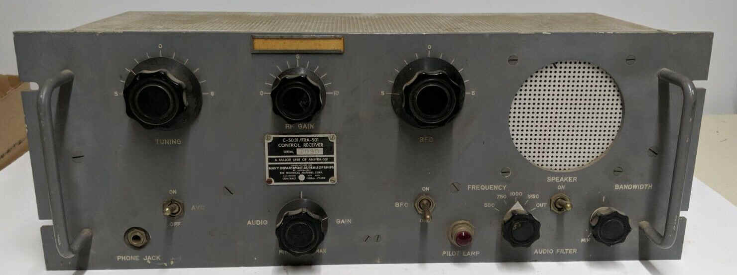
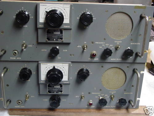
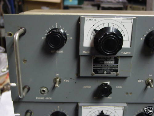
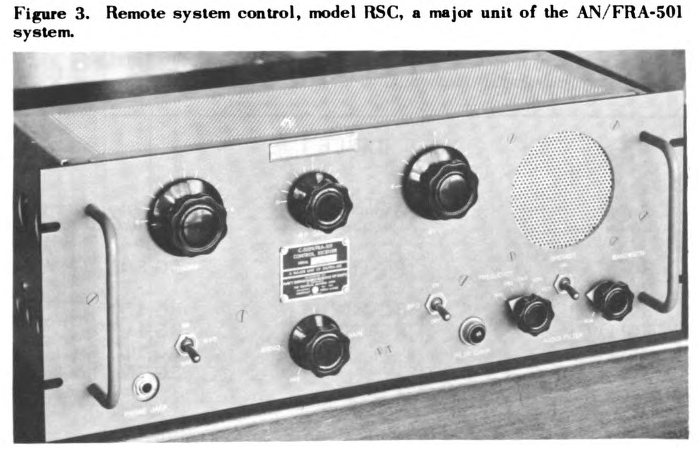
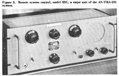
- The remote system control, model RSC (figure 3), in which tones are generated and controlled.
Also in this unit, the returning audio intelligence is amplified and monitored for operating purposes.
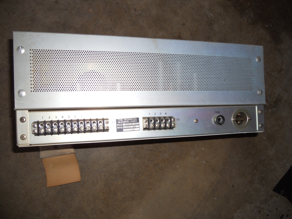
- The remote system filter, model RSF, that receives the output of model RSC and filters the control
tones of harmonic content and improves the wave form.
- The remote system mixer, model RSM, that is used to combine and amplify the tone frequencies that
are generated in model RSC and filtered in model RSF.
At the remote station, there are also three types of equipment in addition to the power supply:
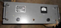
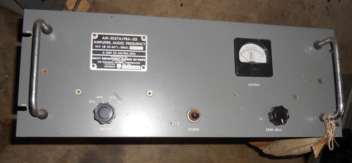
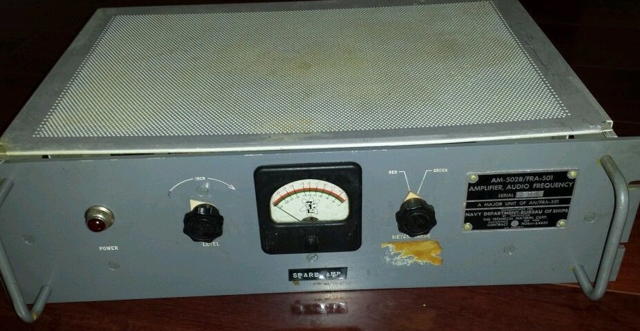
- The remote system amplifier, model RSA, is the initial receiving equipment at the remote site and
is used to amplify the incoming composite signals and to feed them to the discriminator units.
- The remote system discriminator, model RSD, is used to provide the direct current voltages necessary
to control the receiver from a distant station.
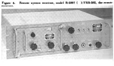
- The remote system receiver, model FRR (figure 4) is used to receive the signals at the remote
station.
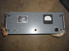
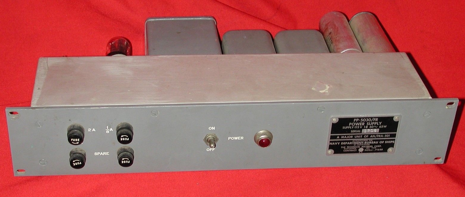
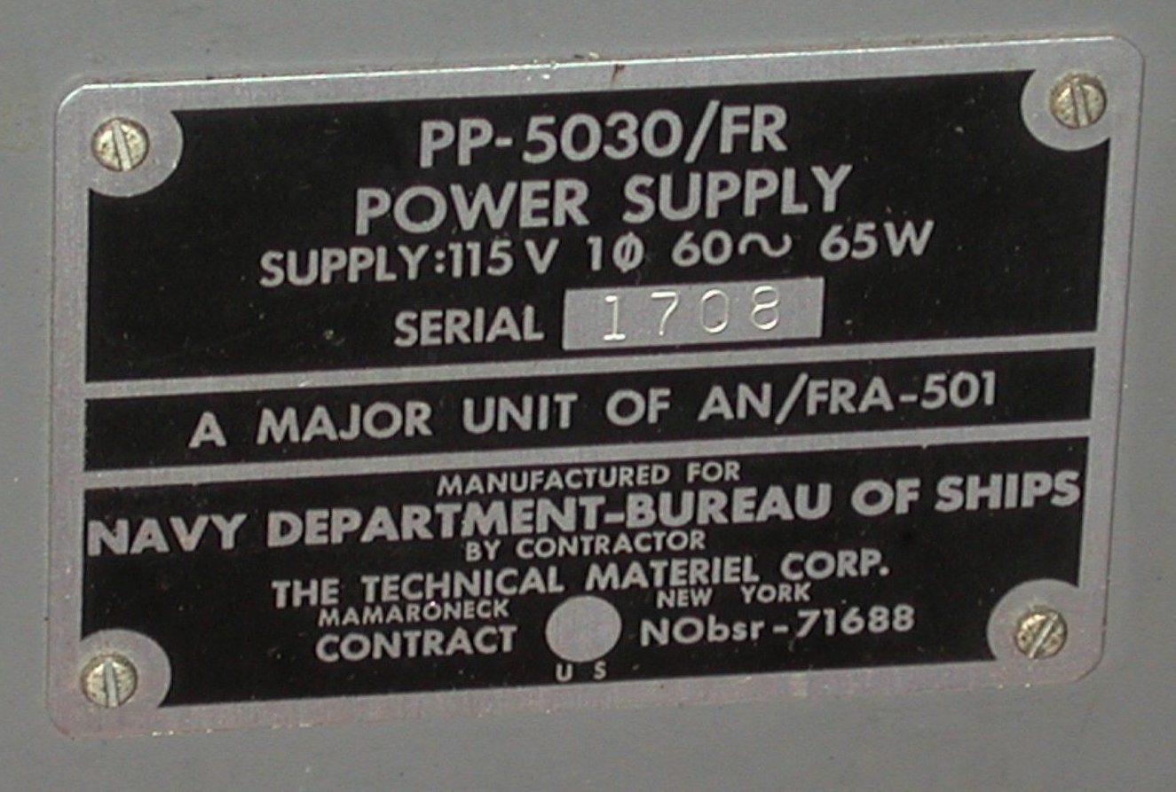
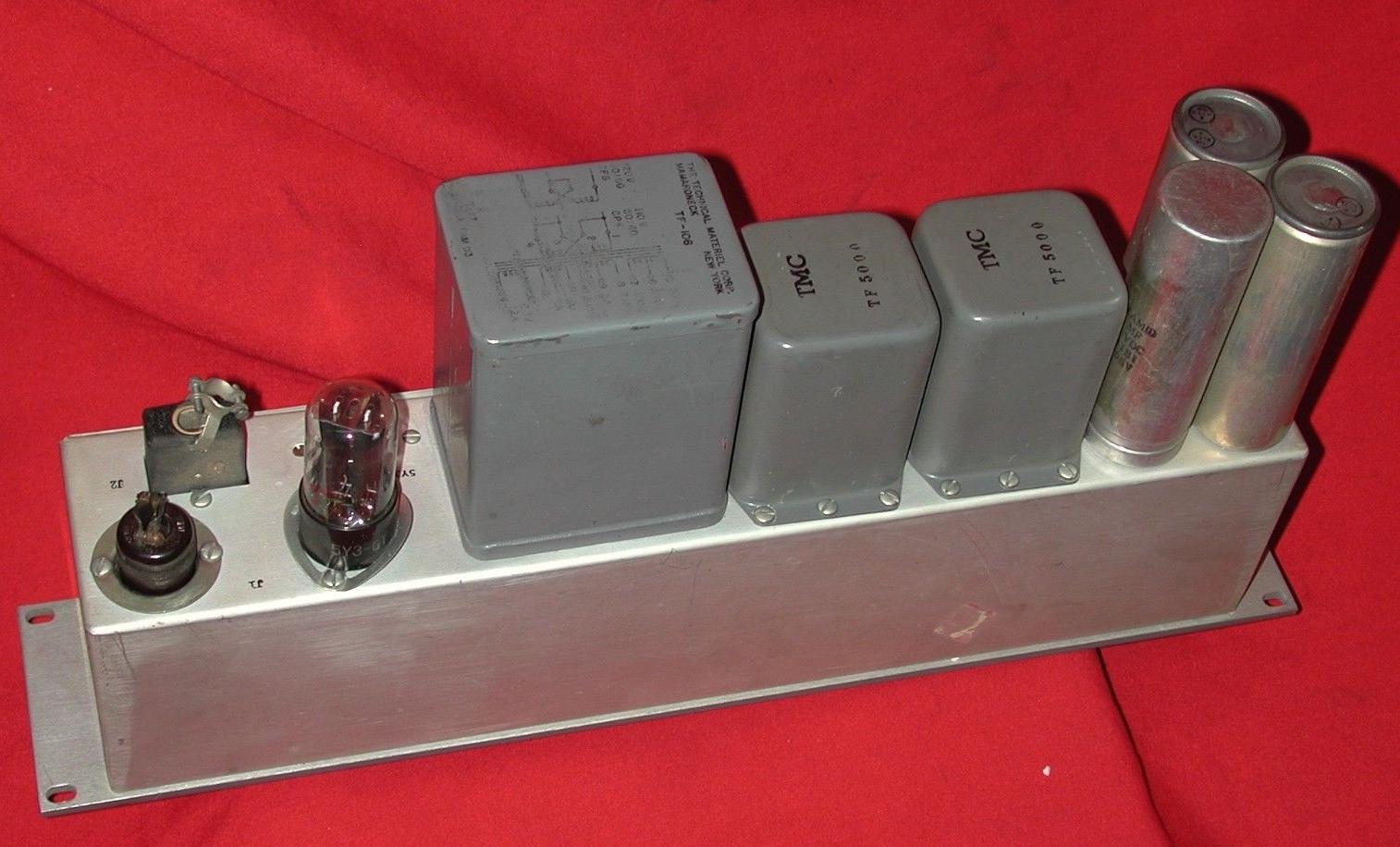
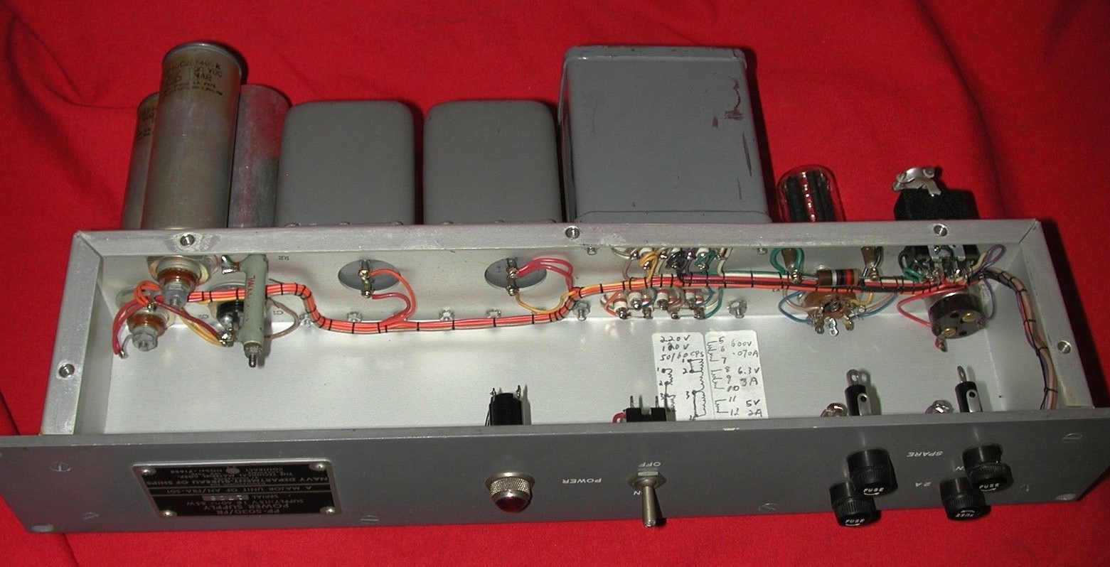
Only one of the units is found in both systems - the power supply, model RSP. The power supply provides
the filament and plate voltages to the control system, the amplifier, and the discriminator.
The control station may have as may as five power supplies; the remote station, as many as
six. The units are identical and may be used interchangeably.
The relative positions of model RSC and model R-5007( )/FRR-502 in the system can be seen in
figure 1 - model RSC at point A on the left and model R-5007( )/FRR-502 at point B on the right.
At the operator's control panel (model RSC), three tones differing by 170 cycles at the
center frequency provide the control functions. One tone is required to vary the
receiver high-frequency oscillator (HFO), a second for the receiver beat frequency oscillator
(BFO), and a third for the receiver radio-frequency gain (RF Gain). A change in frequency in any one of
corresponding change in a receiver function.
In addition, the BFO on/off and automatic volume control (AVC) on/off functions of the remote
receivers are automatically controlled by means of on/off switches on the beat frequency oscillator and
radio-frequency gain control tones, respectively.
At the receiving end of the line or radio link, the components of the composite tone are separated
by mans of channel-tone filters. Each tone is then amplified and discriminated in the remote
terminal. The output of the discriminator is a direct current potential that is
proportional to the deviation of the tone from its center frequency.
This direct current is then used to control the receiver reactance tubes, which in turn
control the high-frequency oscillator and the beat frequency oscillator of the receiver.
Instruction books on maintenance and operation of the equipment have bear
prepared and distributed. Additional copies may be obtained by naval activities
from the nearest forms and publications supply distribution points.
NavShips 92600 covers the control station equipment AN/FRA-501 (AN/FRA-19V) and its
operation with the remote station receiver AN/FRR-502. NavShips 92687 provides information on
receiver AN/FRR-502 (AN/FRR-49(V)). In the latest revisions, the two instruction books
are combined in one volume.