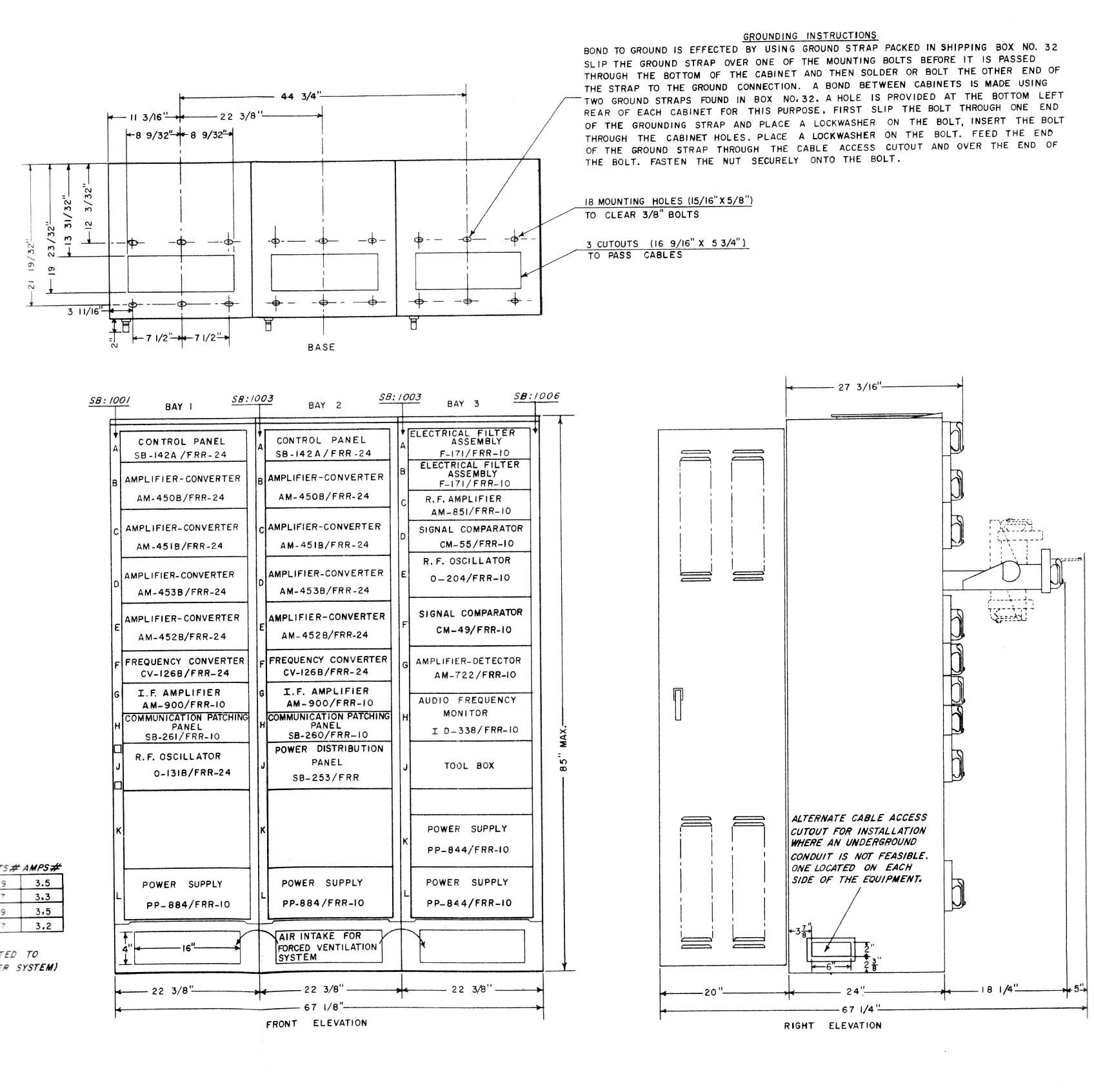
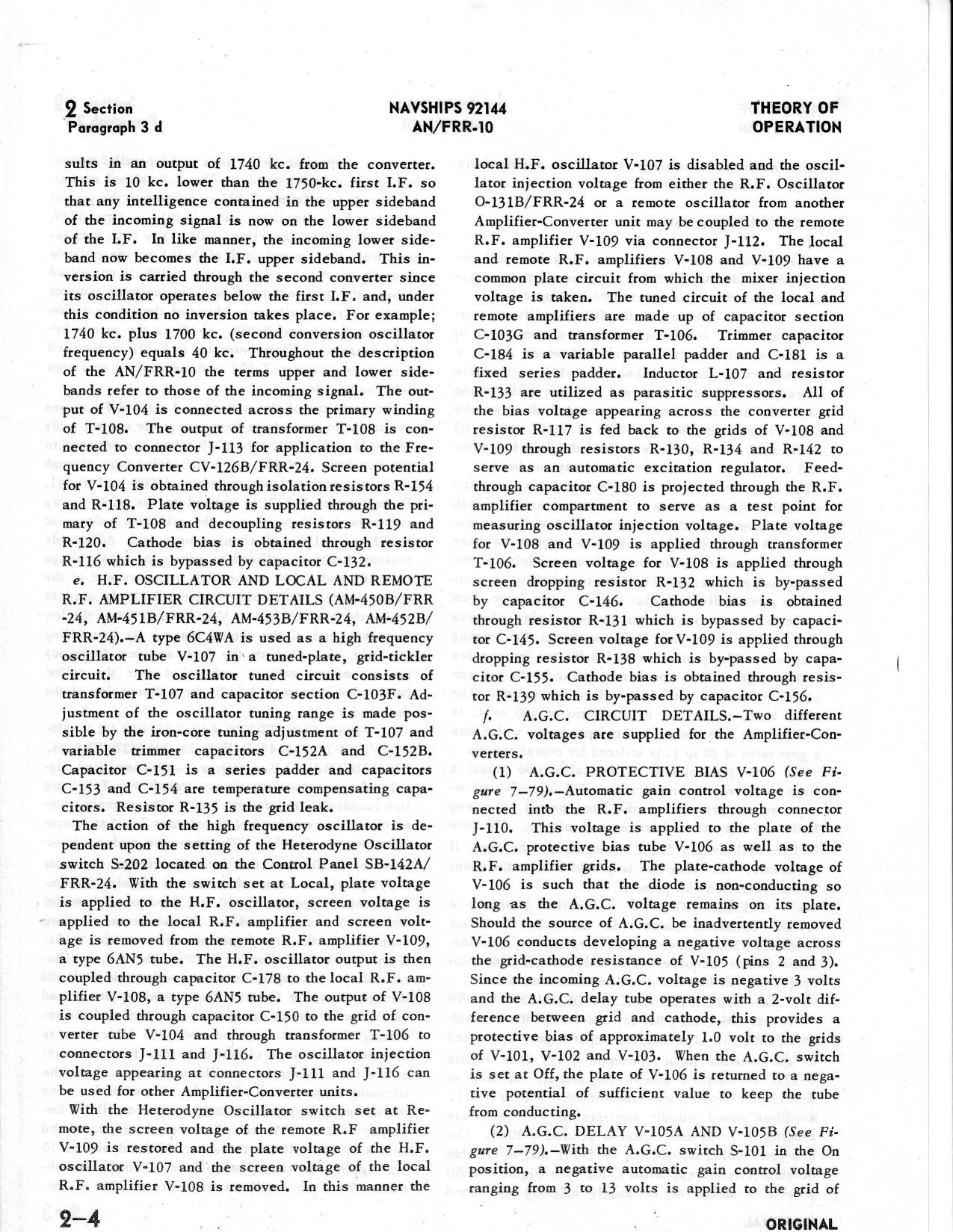
Installation drawing from FRR-10 manual
Circuit Description from 1960 ET2 Rate Training Manual NAVPERS 10190-B
|
|
|
|
|
|
|
|
|
|
Installation drawing from FRR-10 manual |
|
System Configuration - Click on any module name to see a photo - more info coming later 
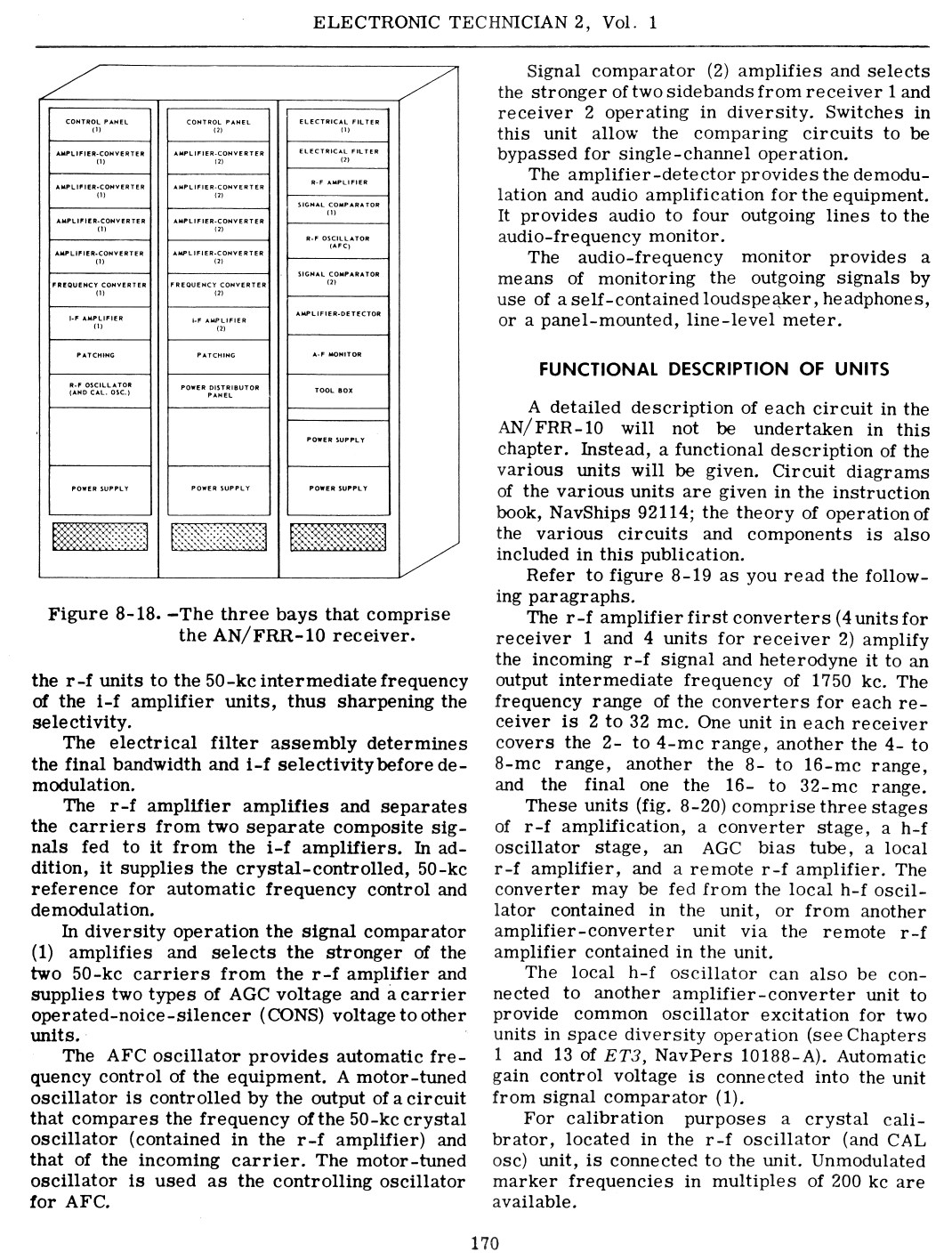
| Module | Rack 1 | Rack 2 | Rack 3 |
| cabinet | CY-1377/FRR-10 | CY-1377/FRR-10 | CY-1377/FRR-10 |
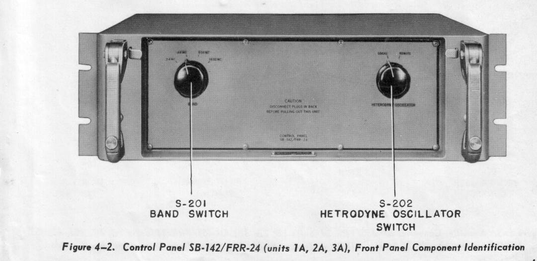
| A | SB-142A/FRR-24 Control Panel Band Switch |
SB-142A/FRR-24 Control Panel Band Switch |
F-171/FRR-10 IF filter |
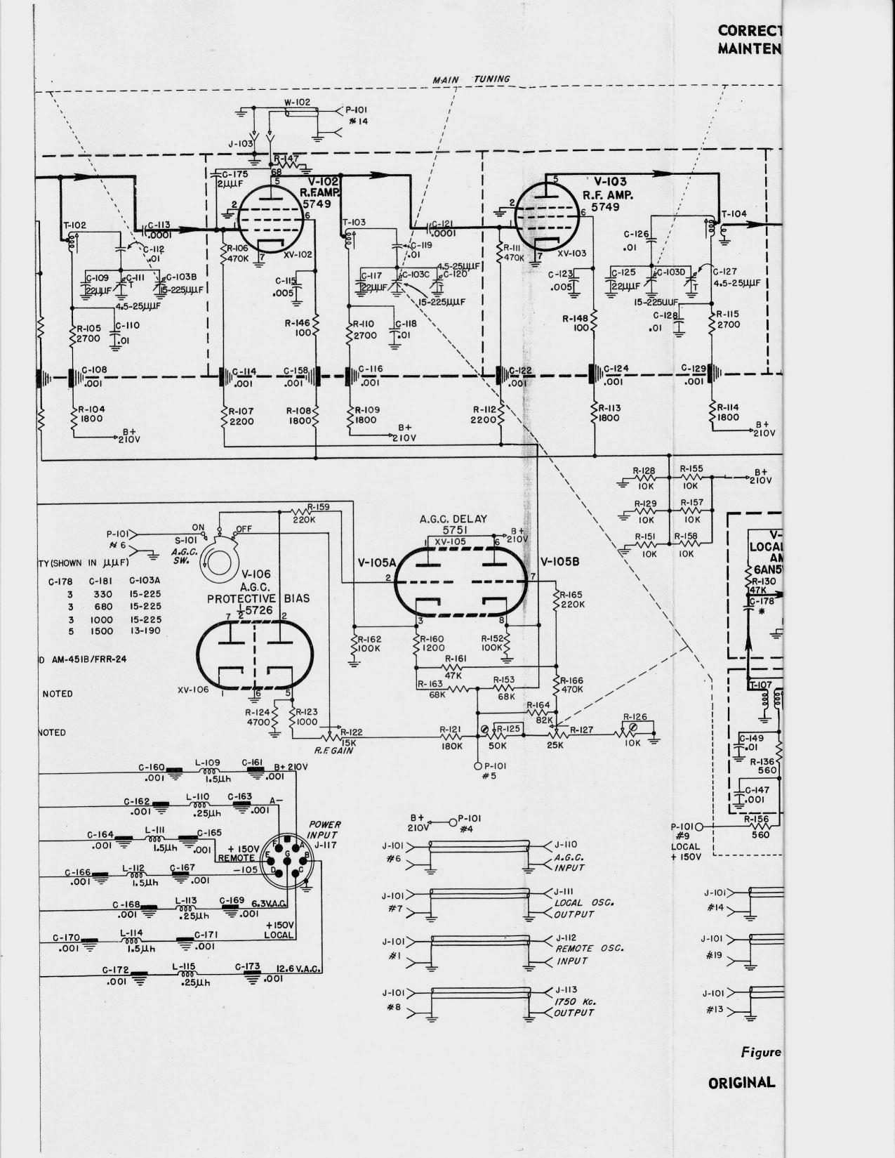
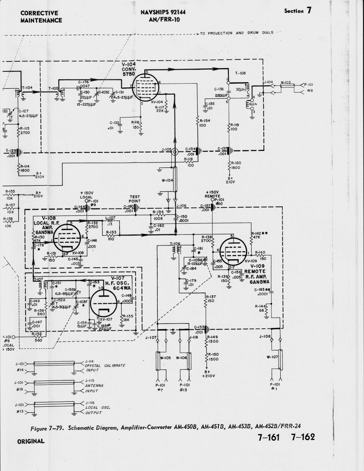
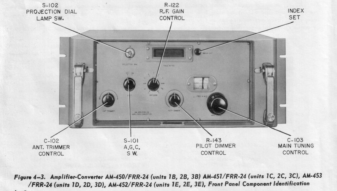
| B | AM-450B/FRR-24 2-4 mc RF 1st converter 1750 kc IF out |
AM-450B/FRR-24 2-4 mc RF 1st converter 1750 kc IF out |
F-171/FRR-10 IF filter |
| C | AM-451B/FRR-24 4-8 mc RF 1st converter 1750 kc IF out |
AM-451B/FRR-24 4-8 mc RF 1st converter 1750 kc IF out |
AM-851/FRR-10 RF amplifier |
| D | AM-453B/FRR-24 8-16 mc RF 1st converter 1750 kc IF out |
AM-453B/FRR-24 8-16 mc RF 1st converter 1750 kc IF out |
CM-55/FRR-10 signal comparator |
| E | AM-452B/FRR-24 16-32 mc RF 1st converter 1750 kc IF out |
AM-452B/FRR-24 16-32 mc RF 1st converter 1750 kc IF out |
O-204/FRR-10 AFC Oscillator |
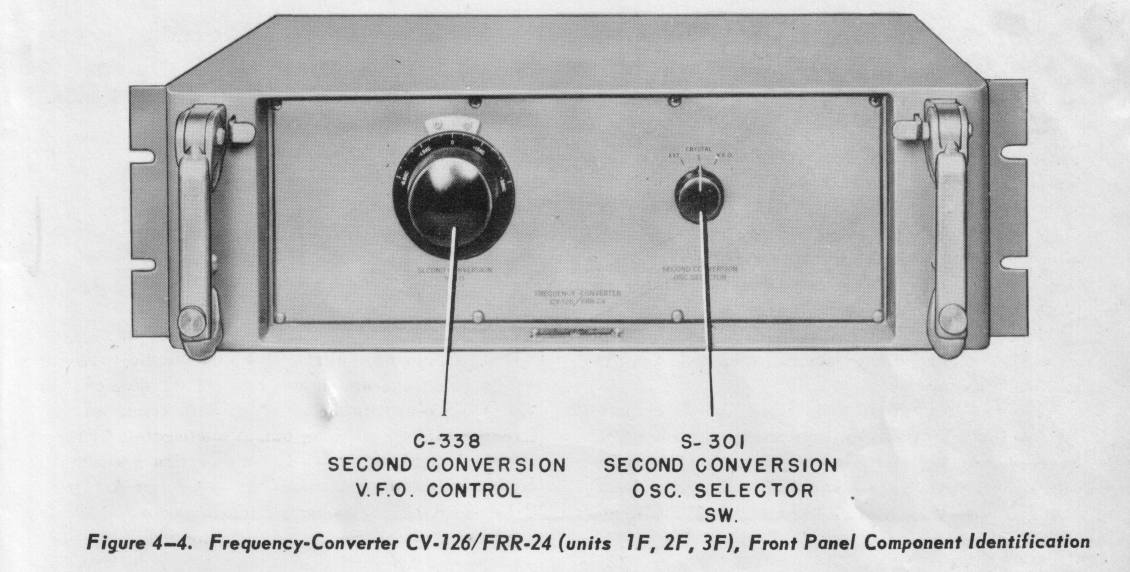
| F | CV-126B/FRR-24 2nd converter 1750 kc IF in 50 kc IF output |
CV-126B/FRR-24 2nd converter 1750 kc IF in 50 kc IF output |
CM-49/FRR-10 signal comparator |
| G | AM-900/FRR-10 50 kc IF amp |
AM-900/FRR-10 50 kc IF amp |
AM-722/FRR-10 amp/detector |
| H | SB-261/FRR-10 patch panel |
SB-260/FRR-10 patch panel |
ID-338/FRR-10 AF monitor |
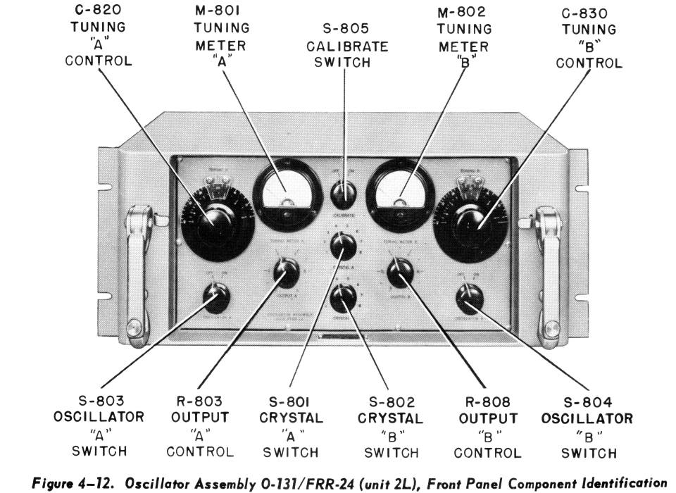
| J | O-131B/FRR-24 Oscillator |
SB-253/FRR Power Distribution Panel |
Tool Box |
| K | Blank
|
Blank | PP-844/FRR-10 Power Supply for Rack 3 |
| L | PP-884/FRR-10 Power Supply for Rack 1 |
PP-884/FRR-10 Power Supply for Rack 2 |
PP-844/FRR-10 Power Supply for Rack 3 |
 |
 |
 |
 |
 |
 |
 |
 |