Go to the Teletype Corp Manuals Page
Please send me email if you have hints, corrections, or a better way to do this.
Note 1 - Found in a box of parts - a handwritten note from Fred Schmidt at Typetronics
"to replace the plastic hammer on the reperf, insert the hammer onto a paper clip
and rotate the reperf to where the hammer lever is most accessible and insert it"
I haven't tried this yet - please let me know about your experience and take
some photos
Note 2 - Here is the procedure I got from Don House -
Note - removing/replacing the side-plate seems difficult to me, particularly if
you have the backspacing option.
1. Do not attempt this without having some time set aside in an area without a phone and good lighting.
2. It is a bit easier if the unit is removed and sitting by itself on a work table where you can get your hands on any part of the unit you need to.
3. Make sure the unit is relatively clean and the parts all move when you turn the shaft.
4. Remove the side-plate or "cover" from the side of the punch and type wheel.
4a. Notice exactly where the home position is on the type wheel.
5. Set up any typing code on the transfer levers that is intended to print.
6. Slowly turn the shaft until the type wheel comes out and the print hammer comes up to print.
7. Depending on which character you set up you might need to remove the type wheel at this point.
7a. Sometimes but not always…
8. Be careful to keep from turning the shaft any further in either direction.
9. Slip the lower portion of the hammer head under the semi-T shaped hammer. The hammer heads are asymmetrical.
10. Us a standard "pull" spring hook to stretch the hammer head over the other side of the T-shaped hammer.
10a. If you pull too hard it is possible, but not probable, that you might tear the hammer head or it's substitute.
11. Put everything back together that was necessary to remove.
Note 3 - I have also removed the entire hammer lever and ribbon guide
assembly out the back,
but I think the method below is easier - thanks to Tom Tillson for the pointer..
"It is a damn poor job that doesn't require at least one new tool"
If you don't have a couple of spring hooks, make or buy some - they come in handy
Crochet hooks, bent paper clips, or the real thing from Central
Tools
The M28 typing reperf (this one is chadless and has power
backspace)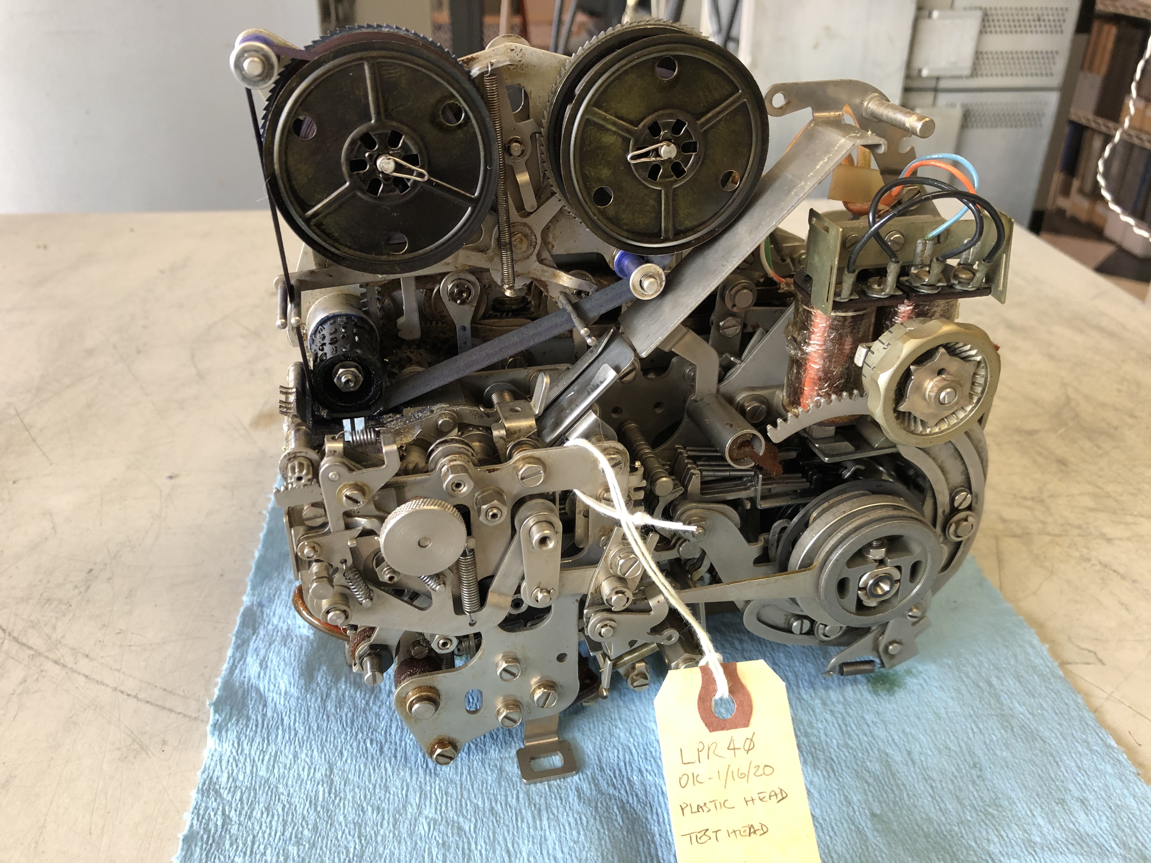 |
View of the punch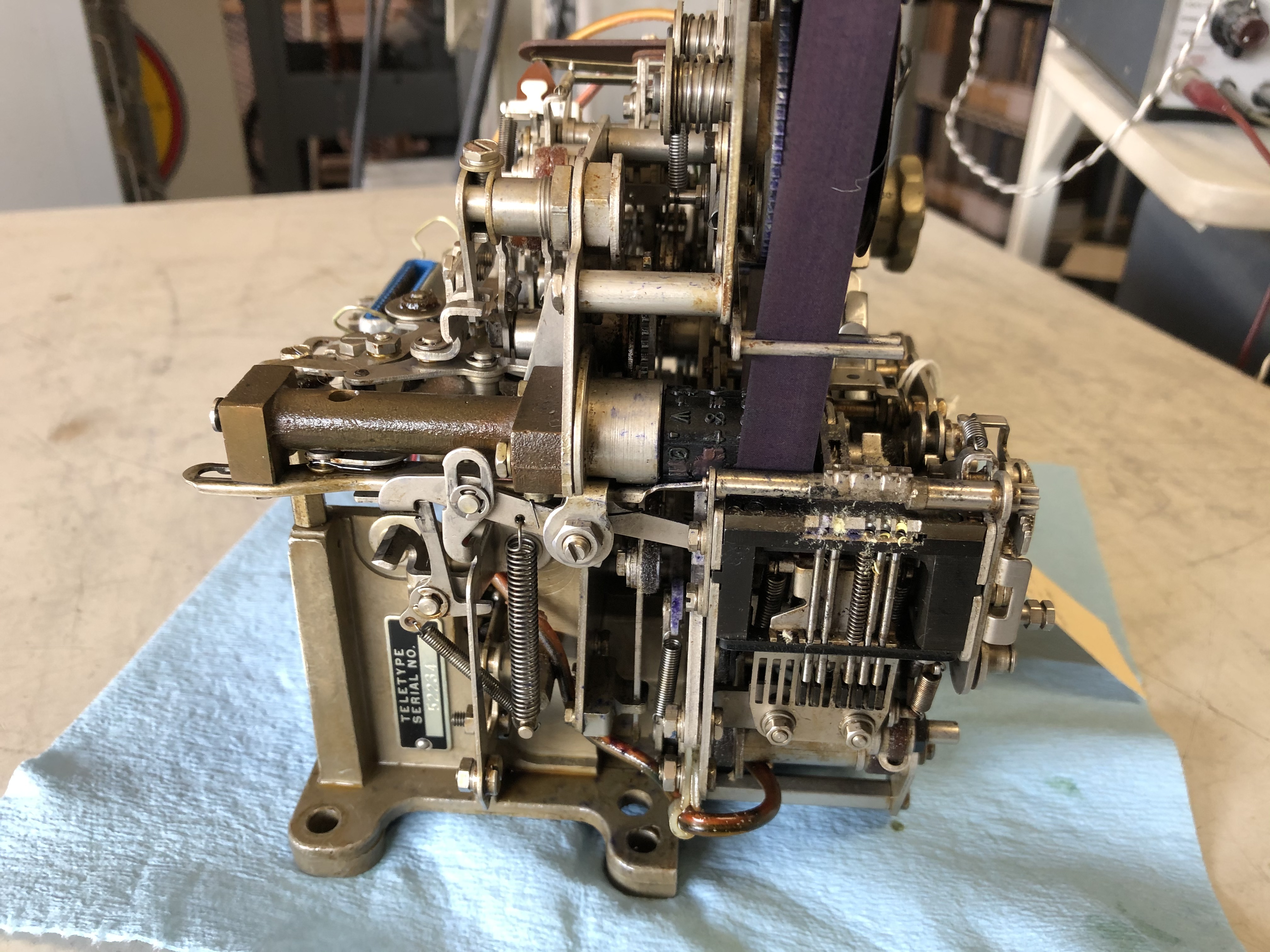 |
This is the plastic print hammer head - yours may be missing
or cracked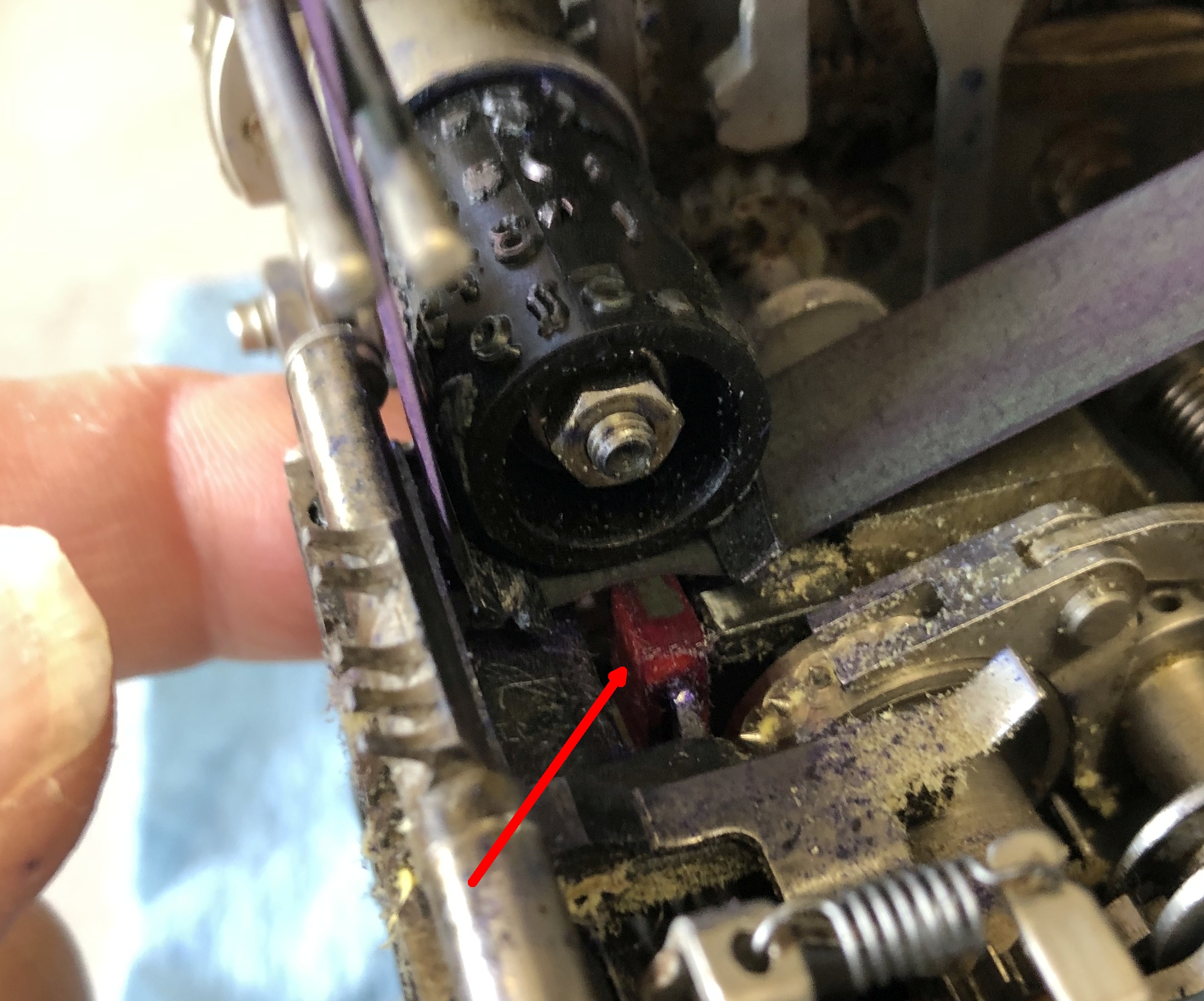 |
We will remove the punch block to get access to
remove/replace the head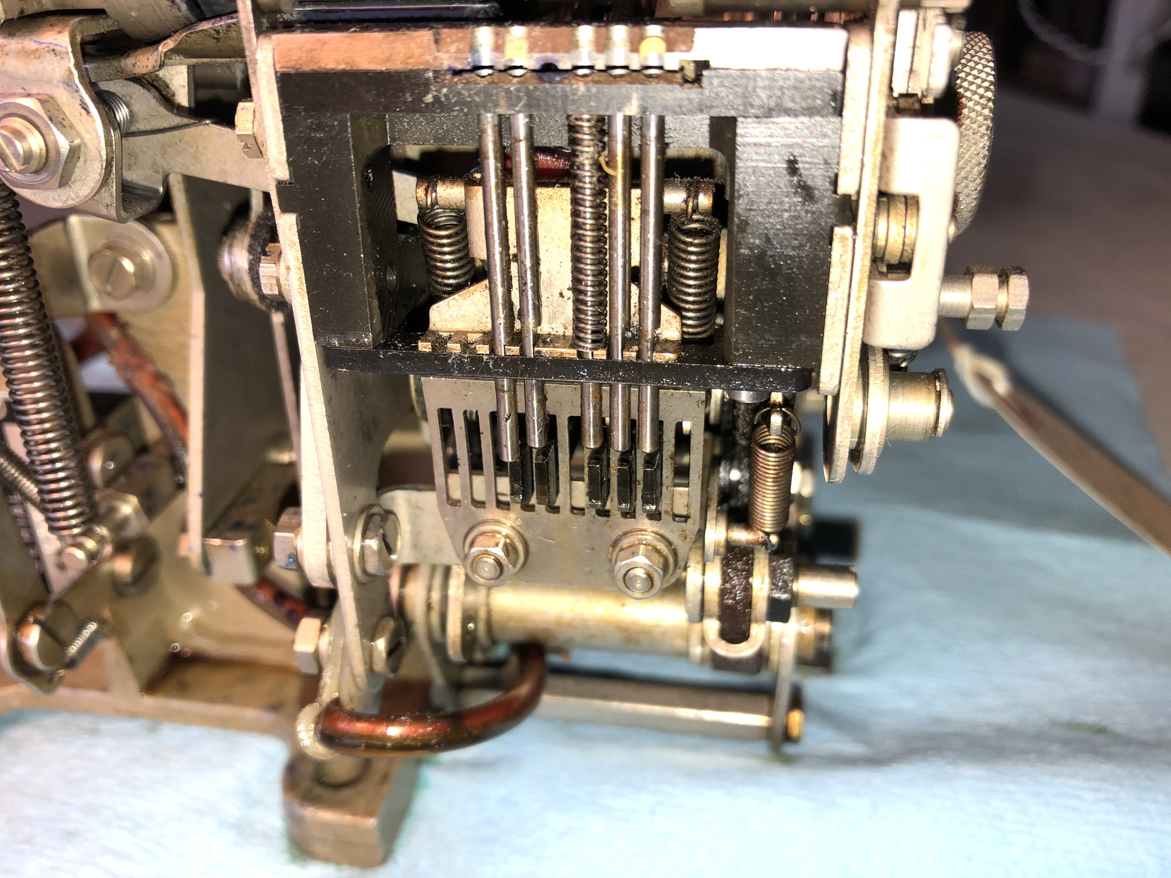 |
| Remove two screws on each side (a 3/16 wrench is handy) 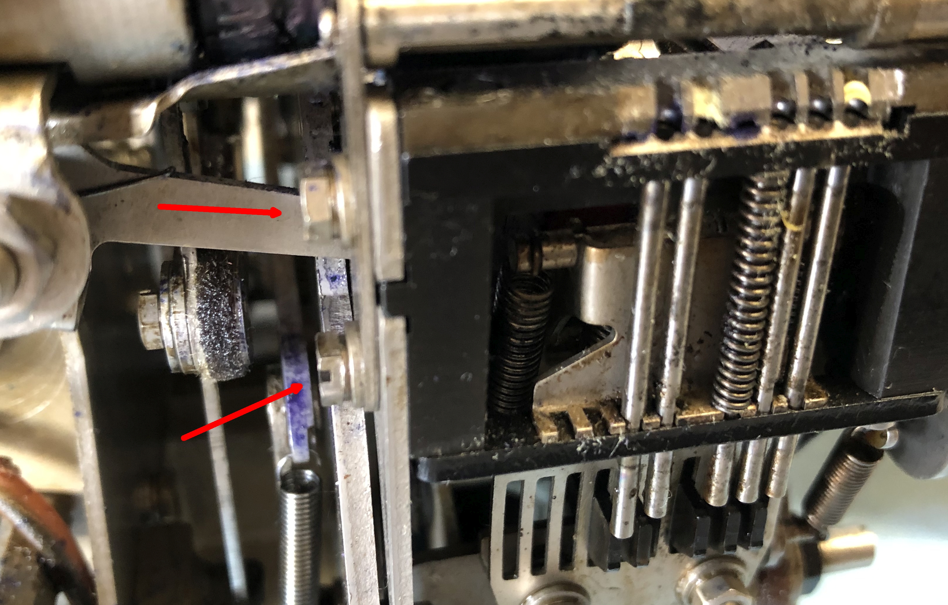 |
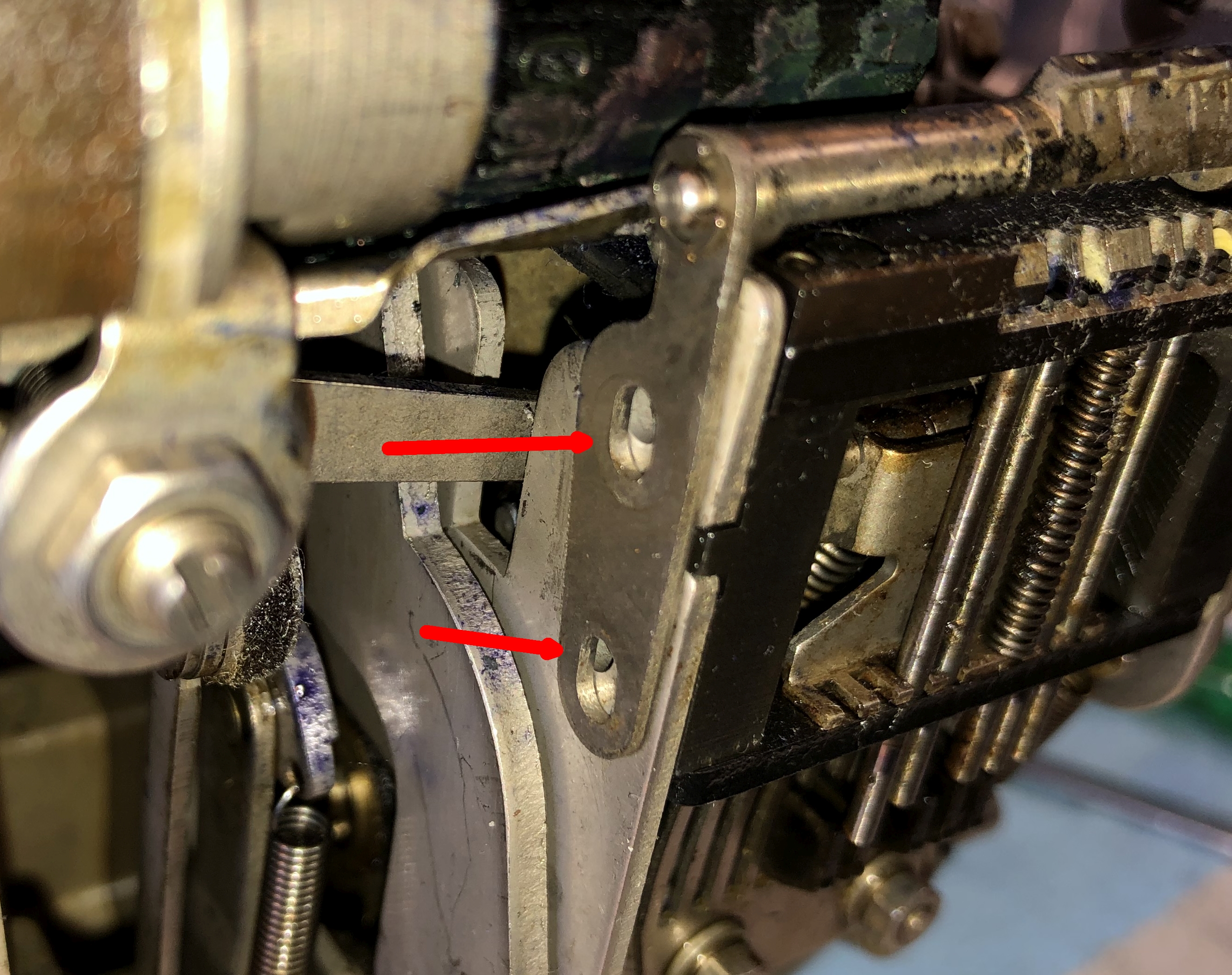 |
The backspace mechanism has a screw and a stud - you may
just have two screws on this side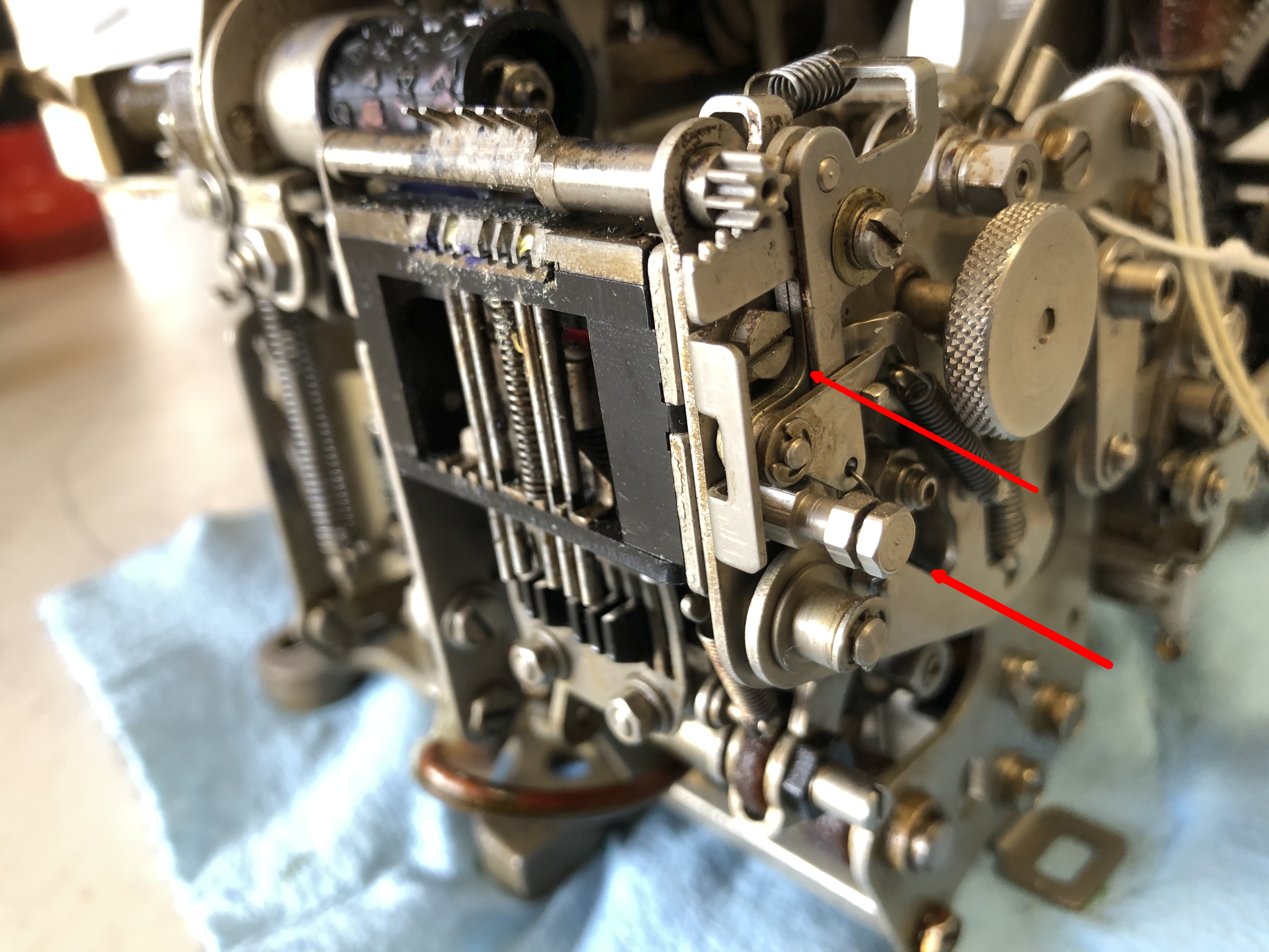 |
Stud and bracket removed from backspace mechanism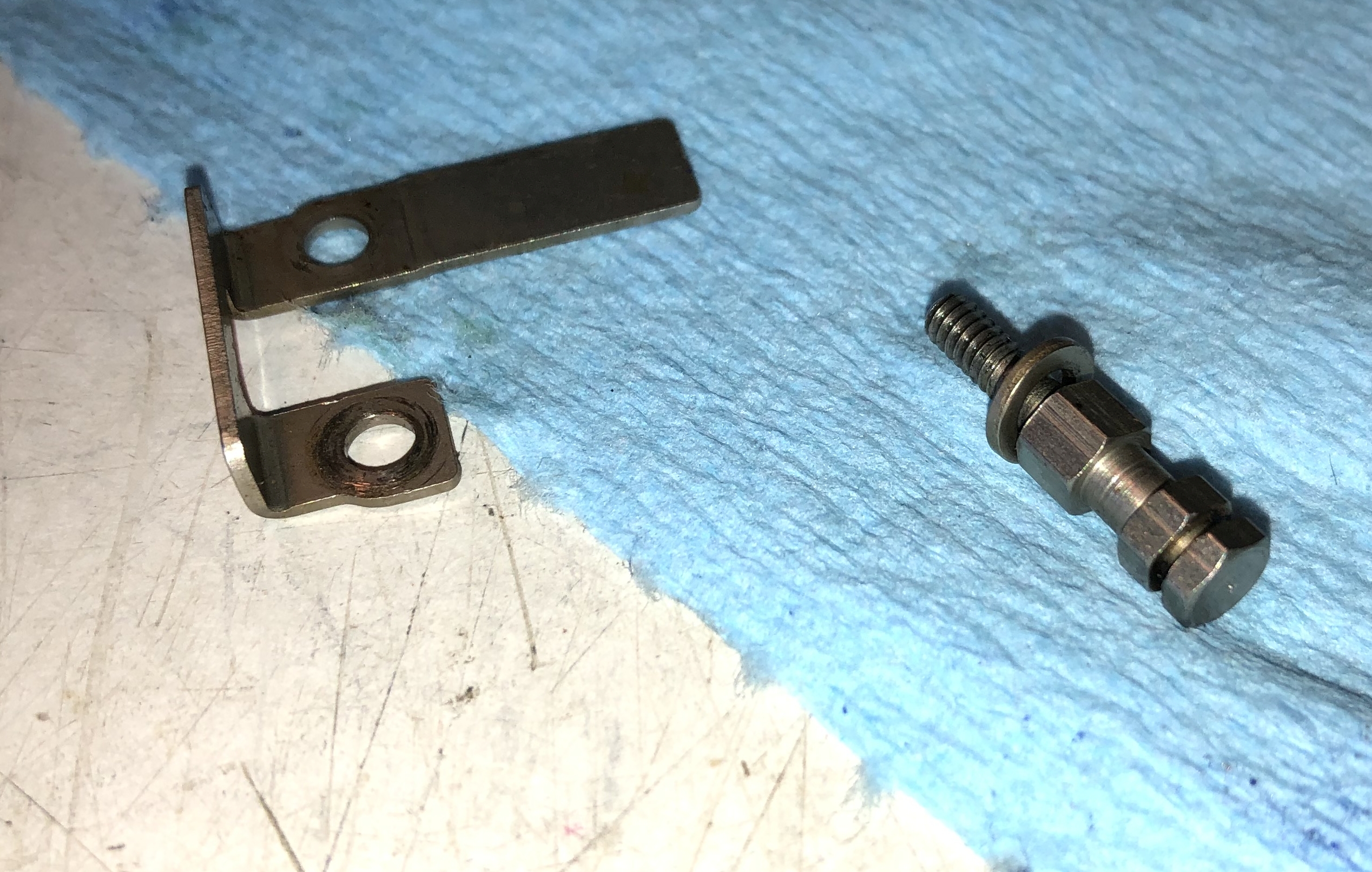 |
The punch pins are retracted by 4 springs - you need to
detach these at their bottom ends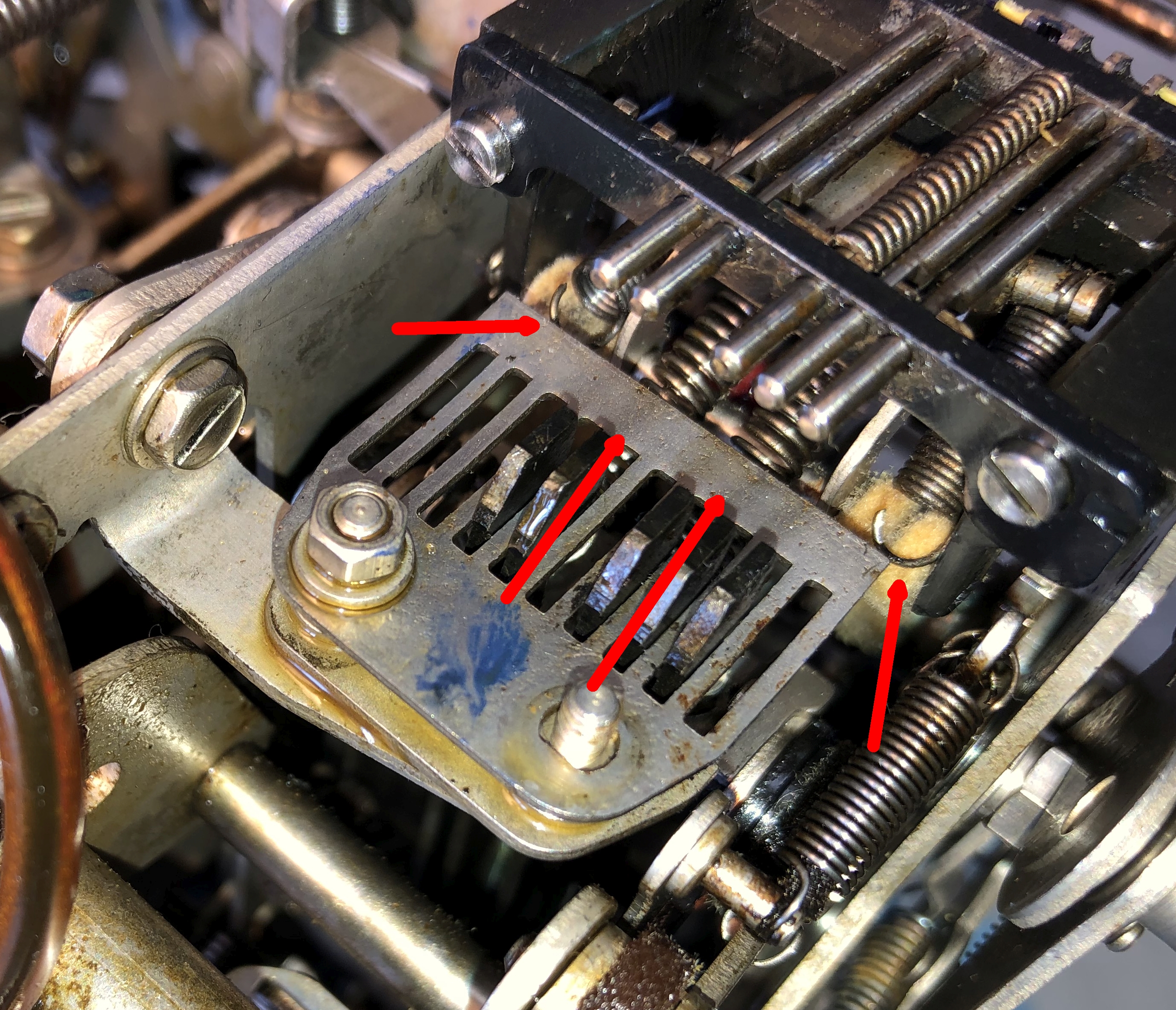 |
Remove the punch lever guide plate and you get access to
detach the springs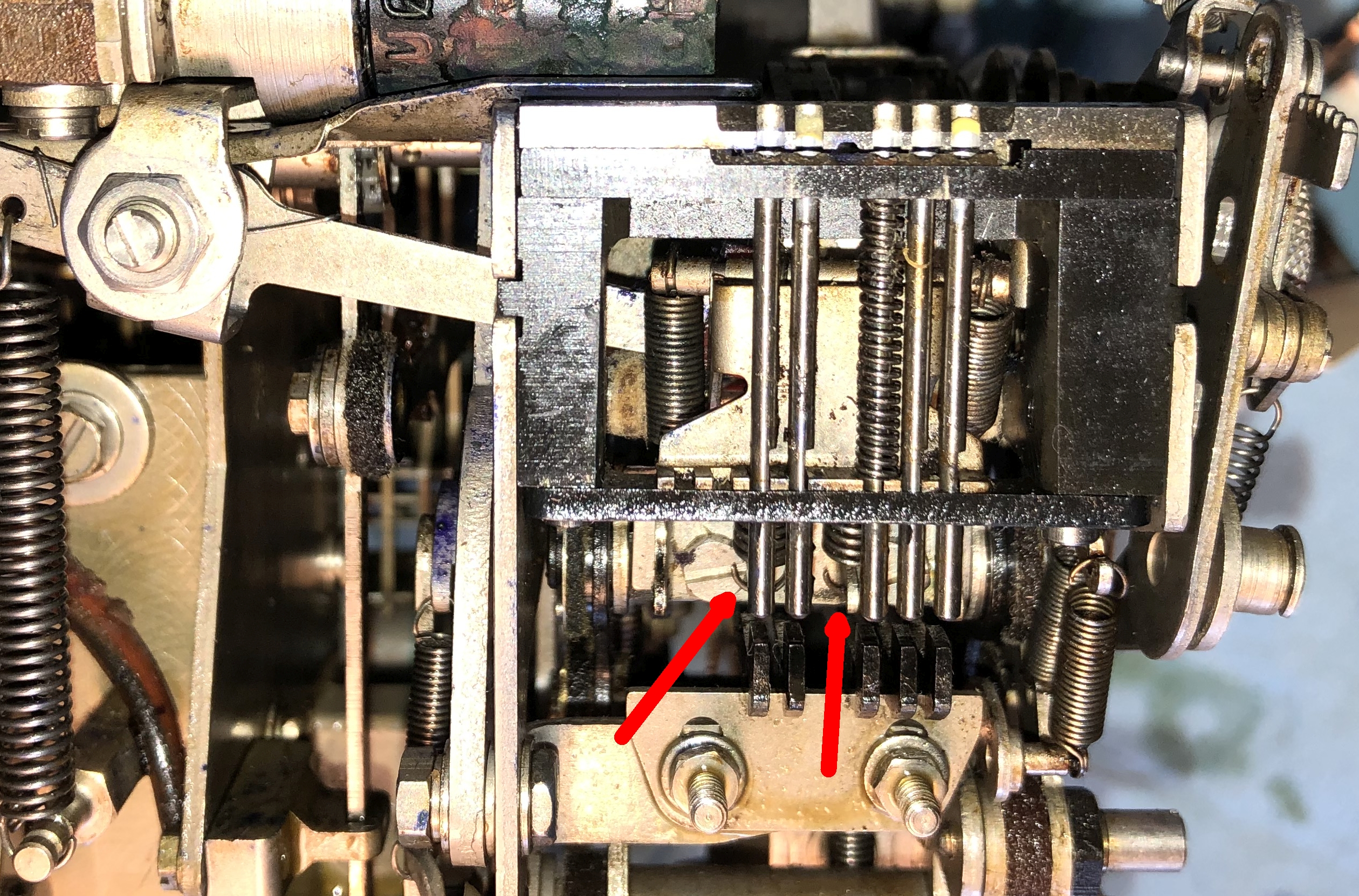 |
After the springs are detached you can slide the punch block
out - it fits into slots in the side plates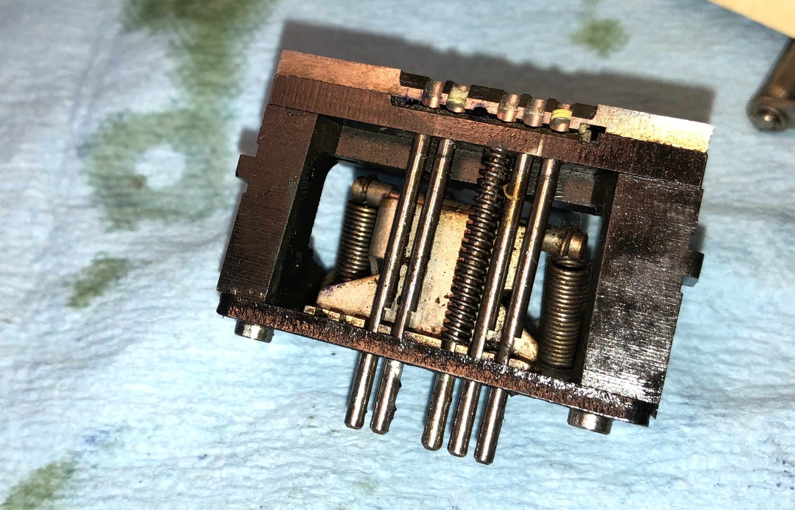 |
Rear of the punch block showing those 4 pesky springs still
attached at the top and detached at the bottom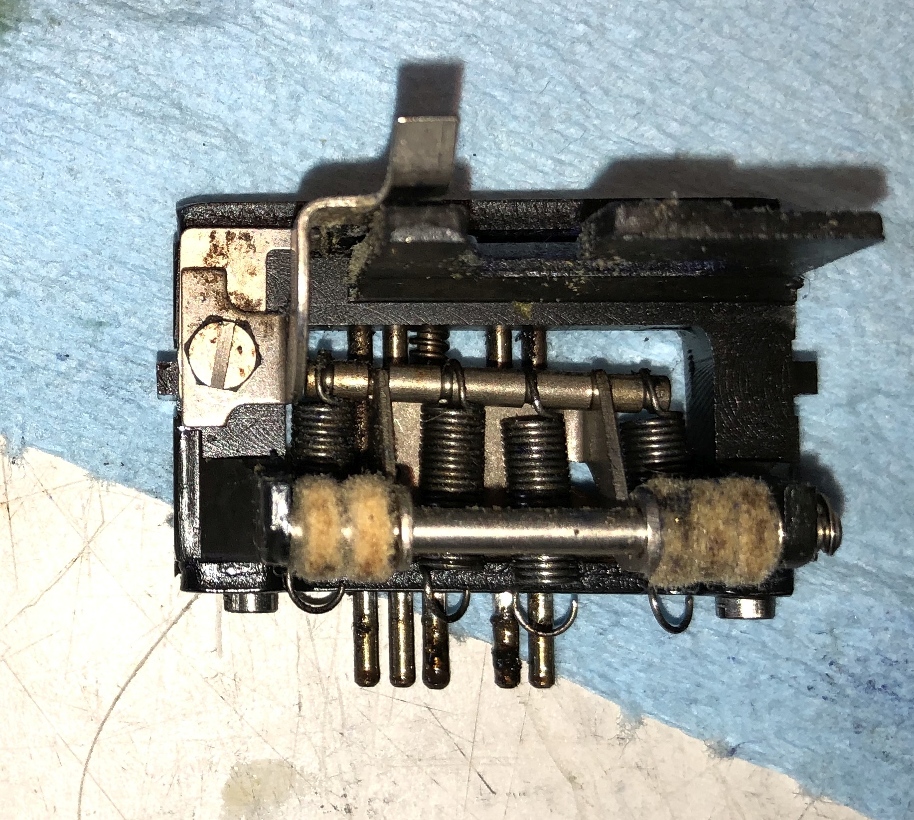 |
The old hammer is now exposed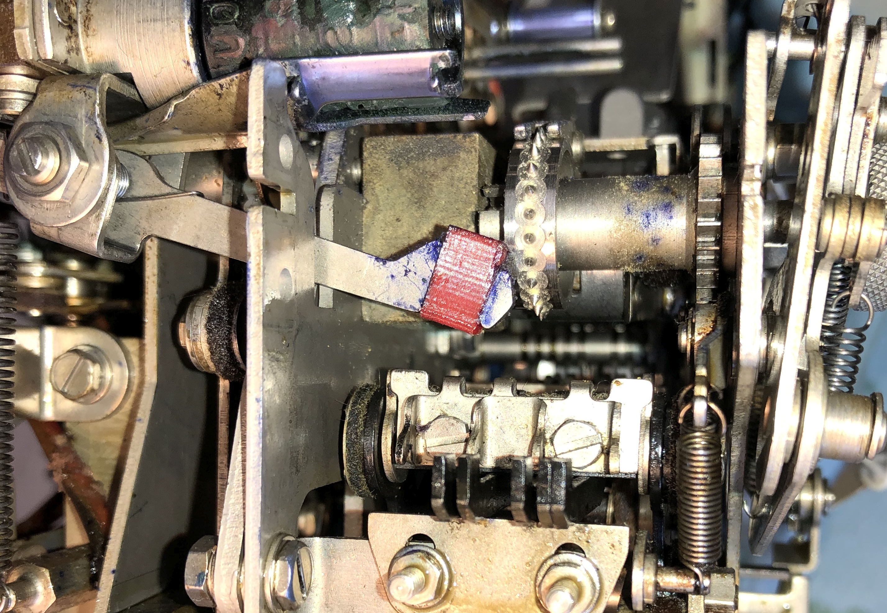 |
I used long nosed pliers to remove the old one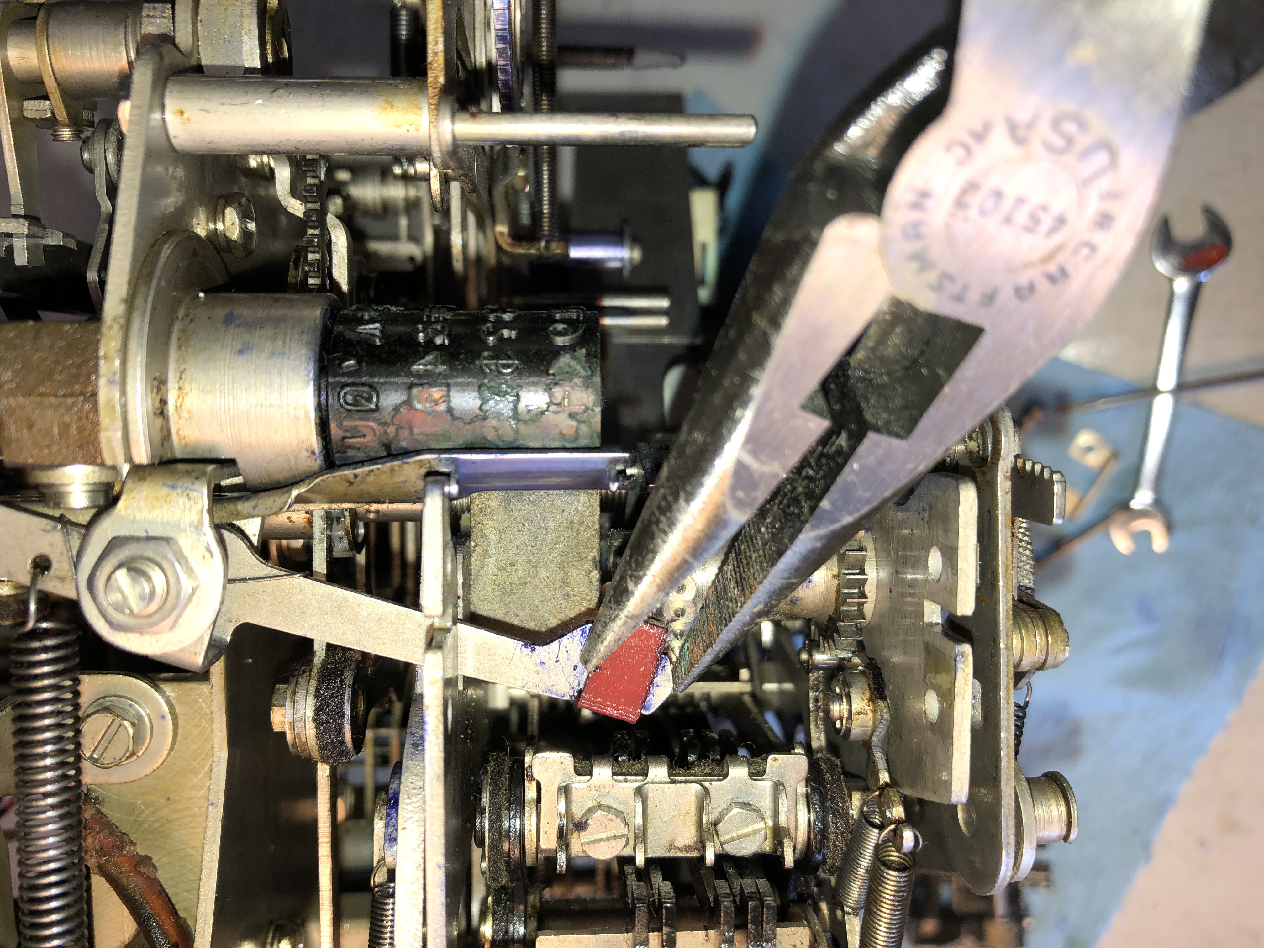 |
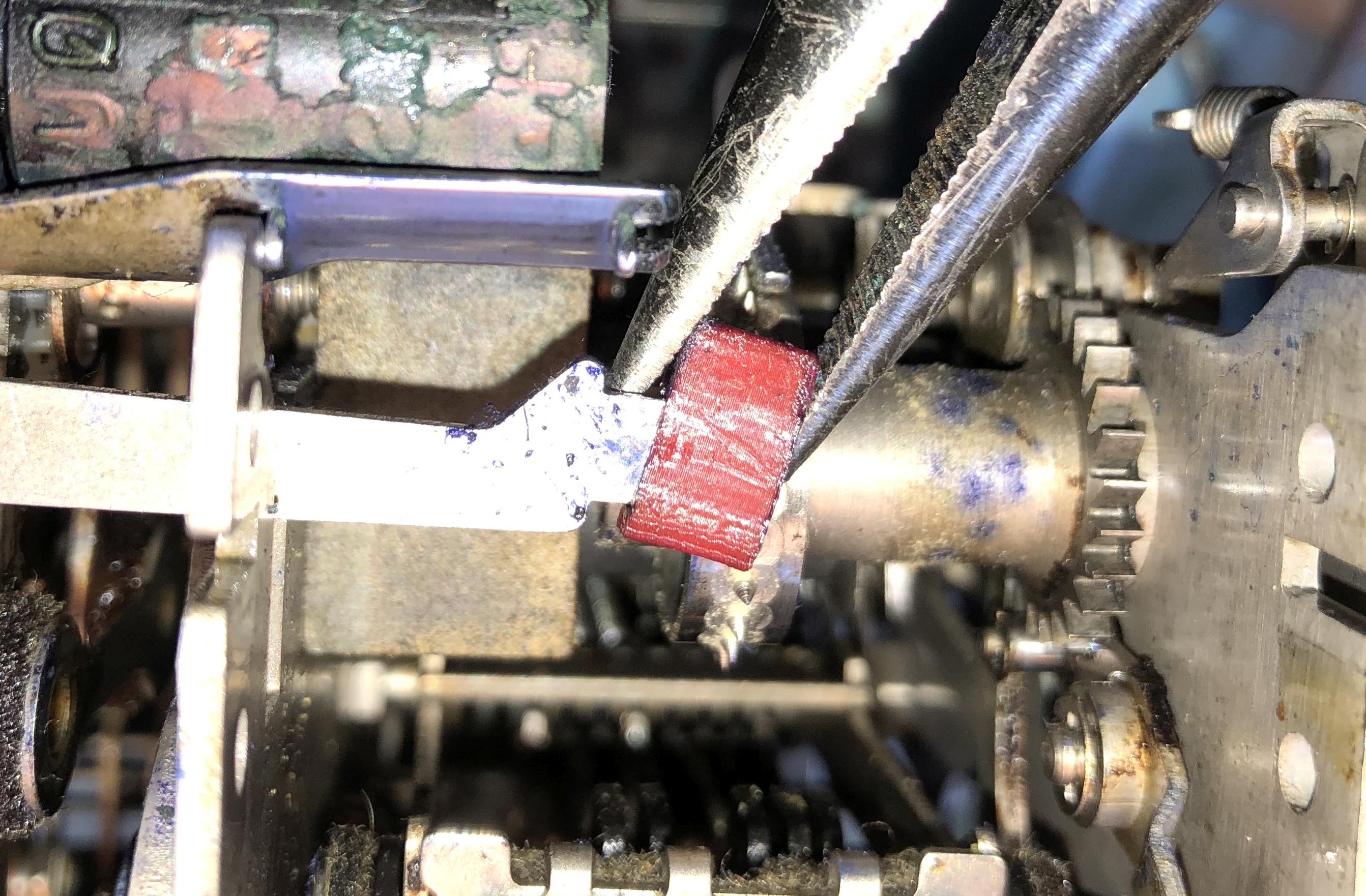 |
Hammer lever with no head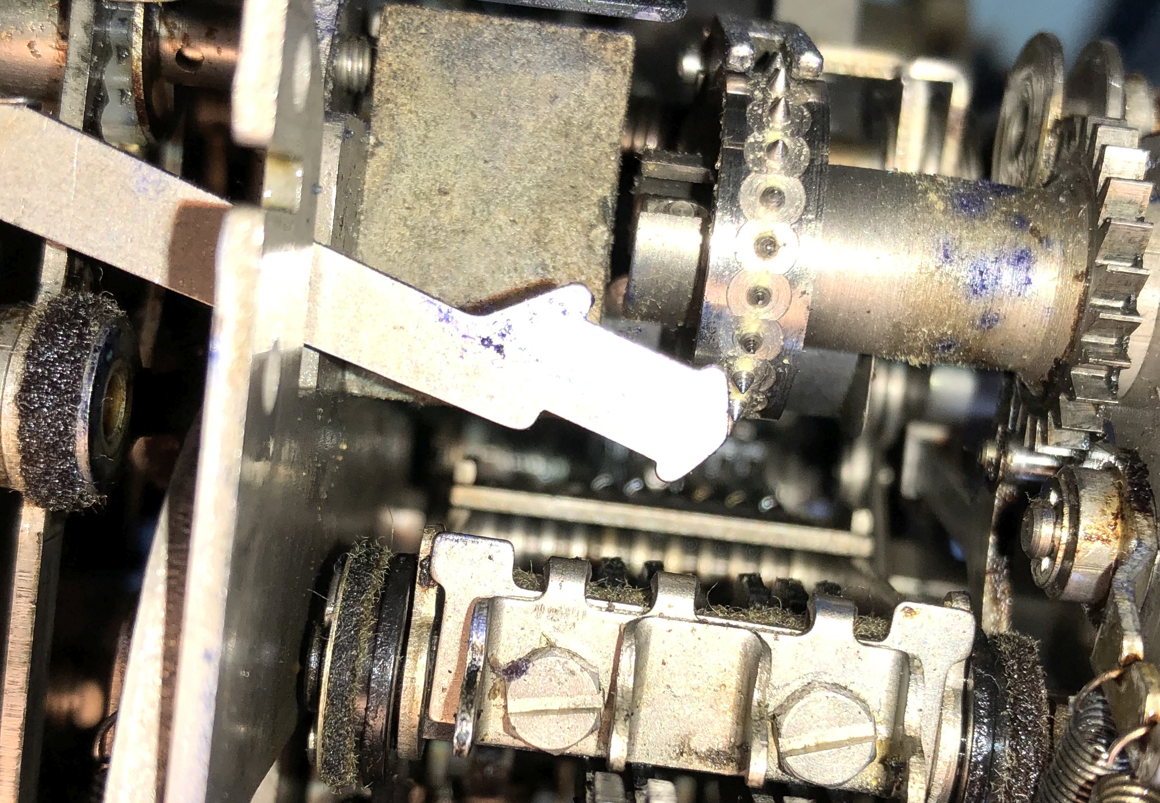 |
Replacing the head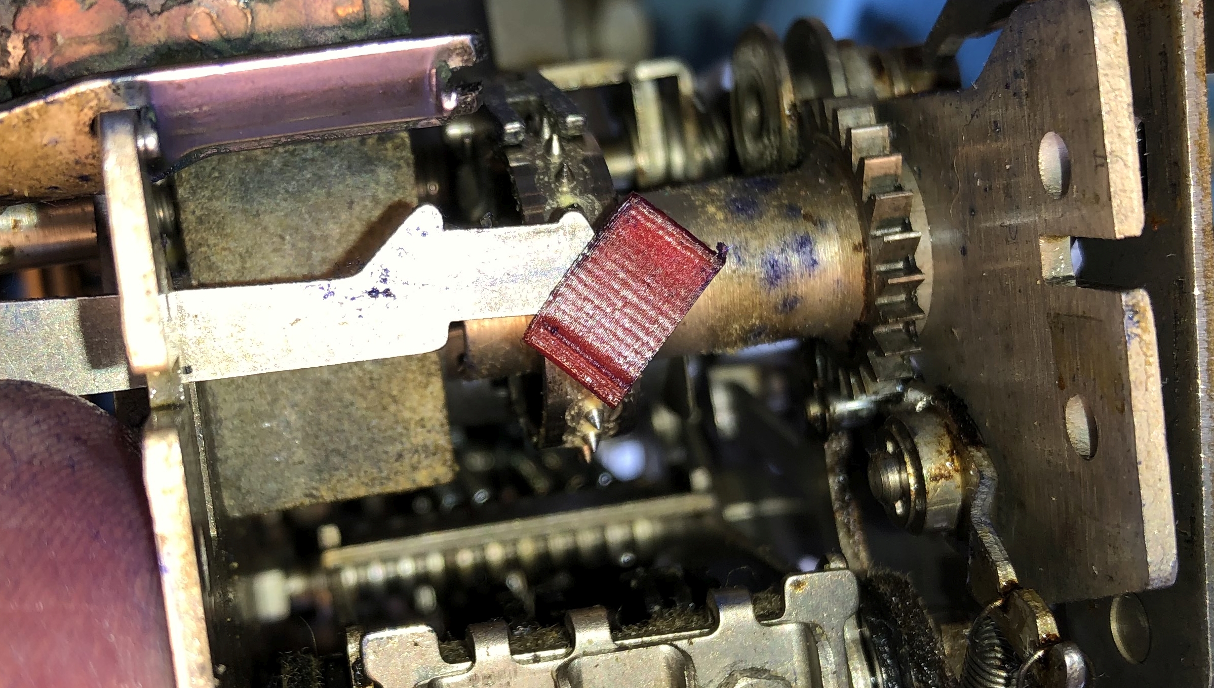 |
It is flexible so you need to get it started and just push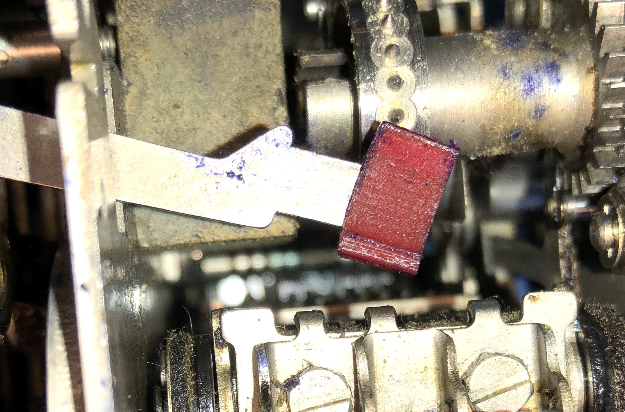 |
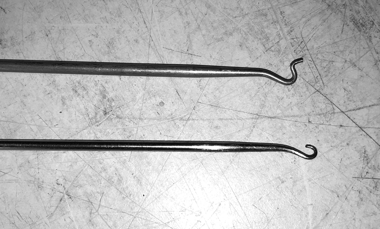
IMPORTANT - THE THICK PART OF THE HEAD FACES UP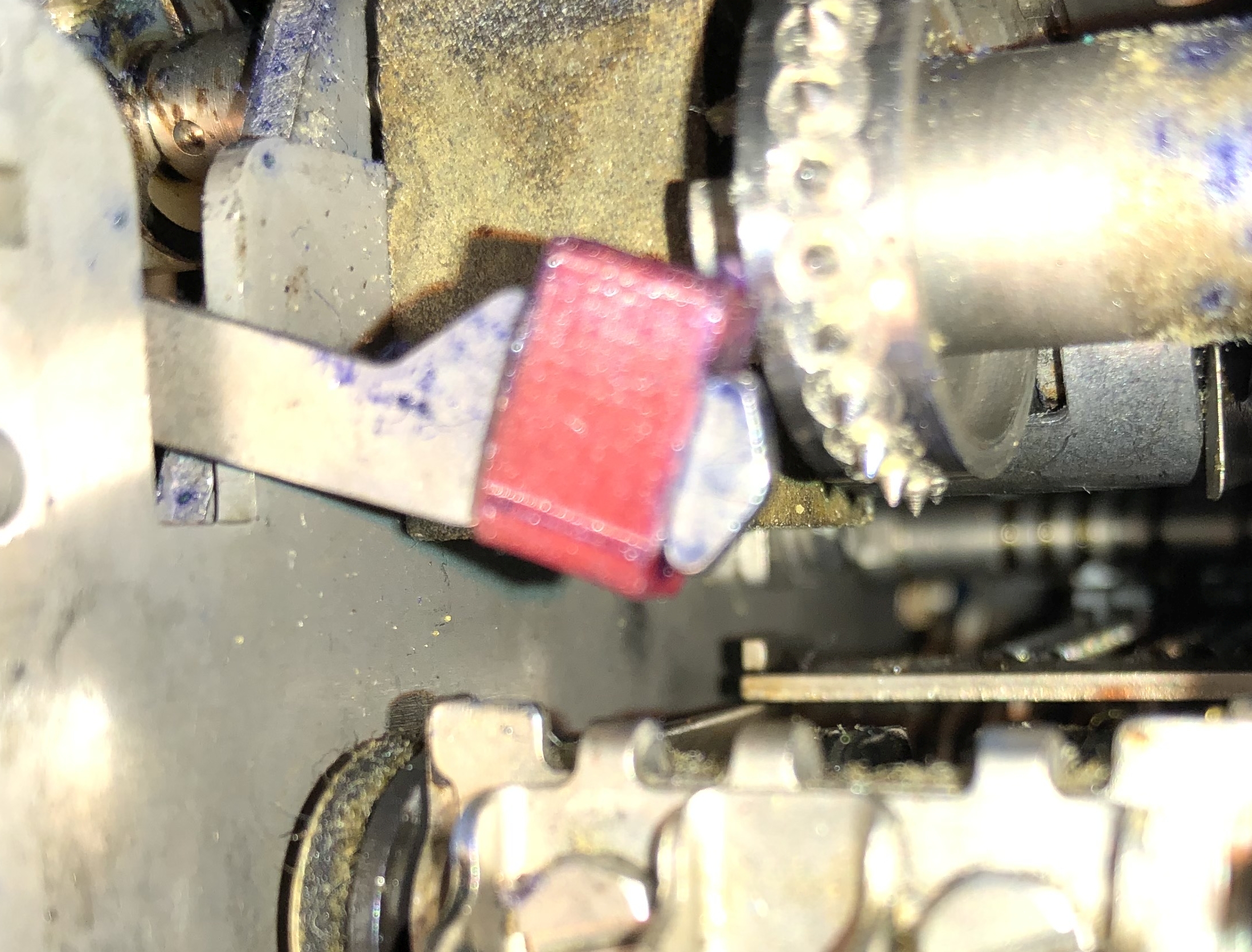 |
IMPORTANT - THE THICK PART OF THE HEAD FACES UP -
HERE'S A DIFFERENT HEAD SHOWING THIS 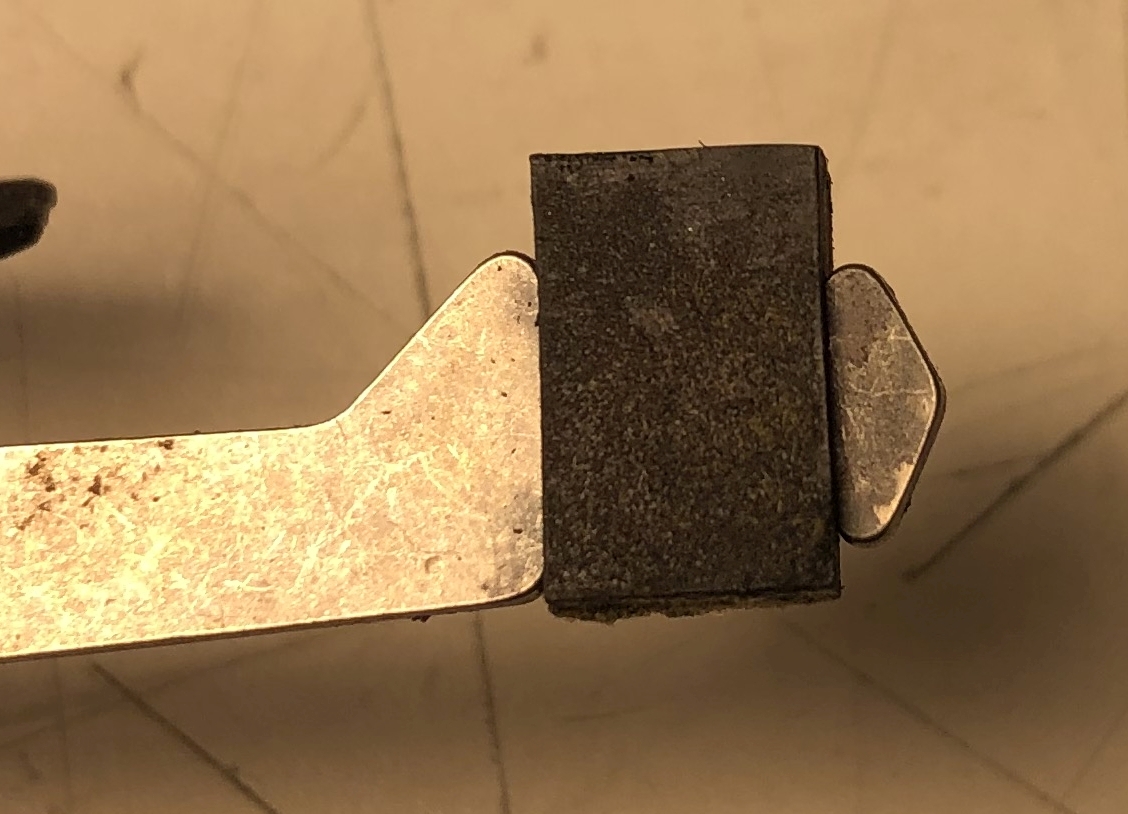 |
Slide the punch block back in and replace the two screws on
each side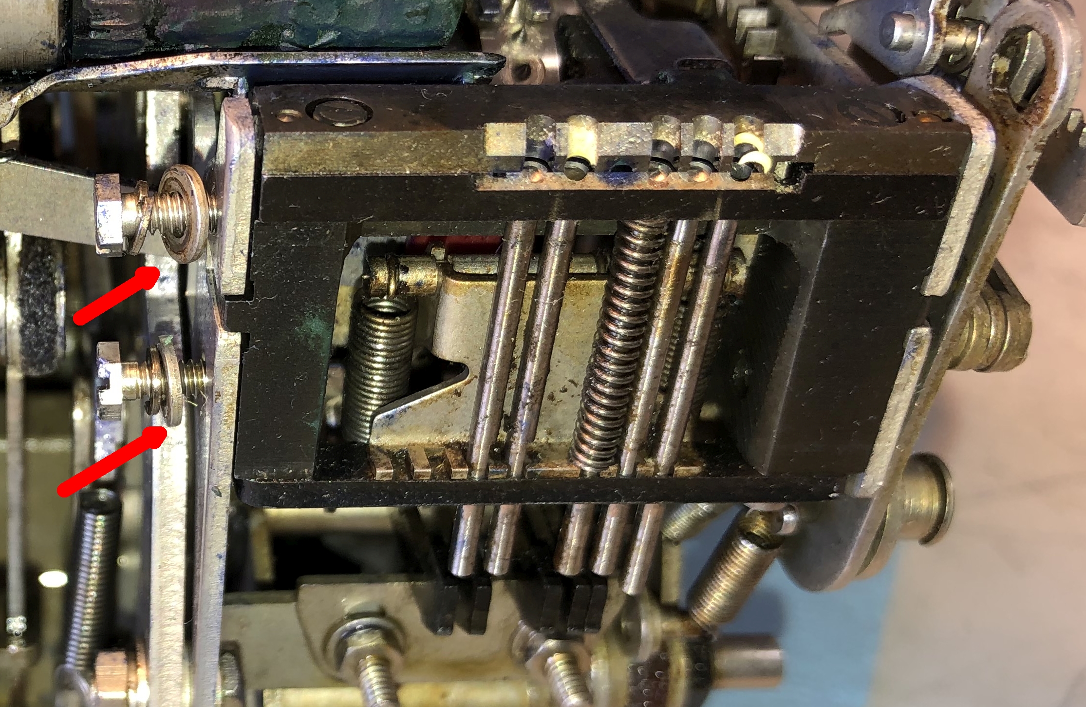 |
Re-attach the 4 punch springs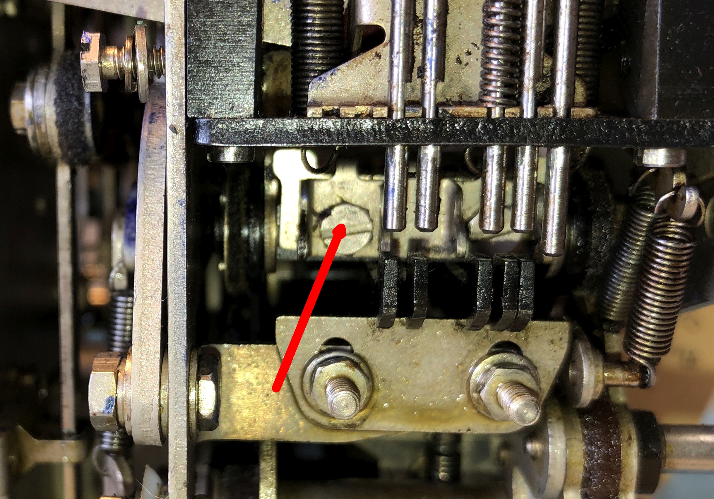 |
Using the spring hook to re-attach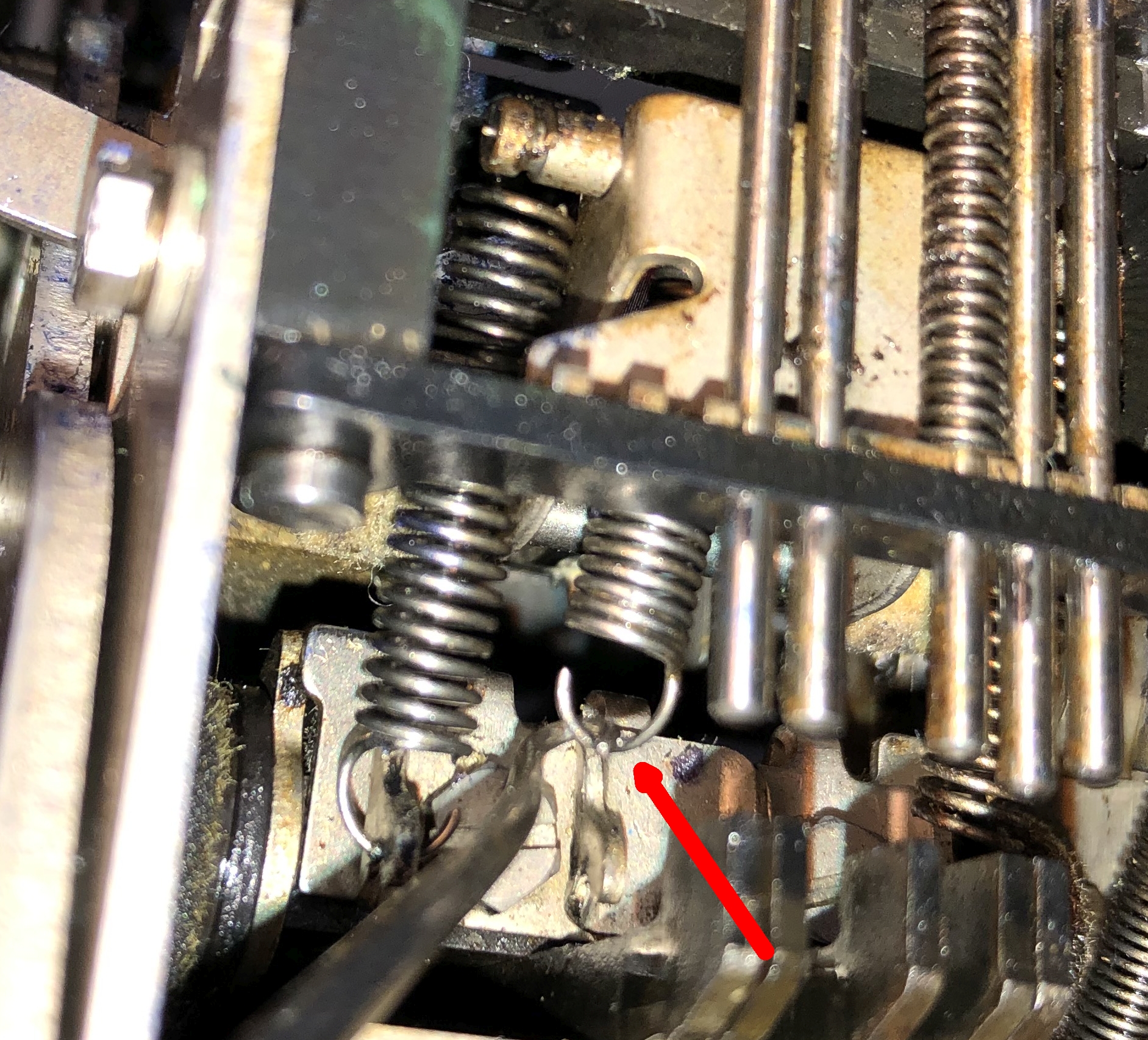 |
Re-install the punch lever guide plate, making sure the
levers align with the punch pins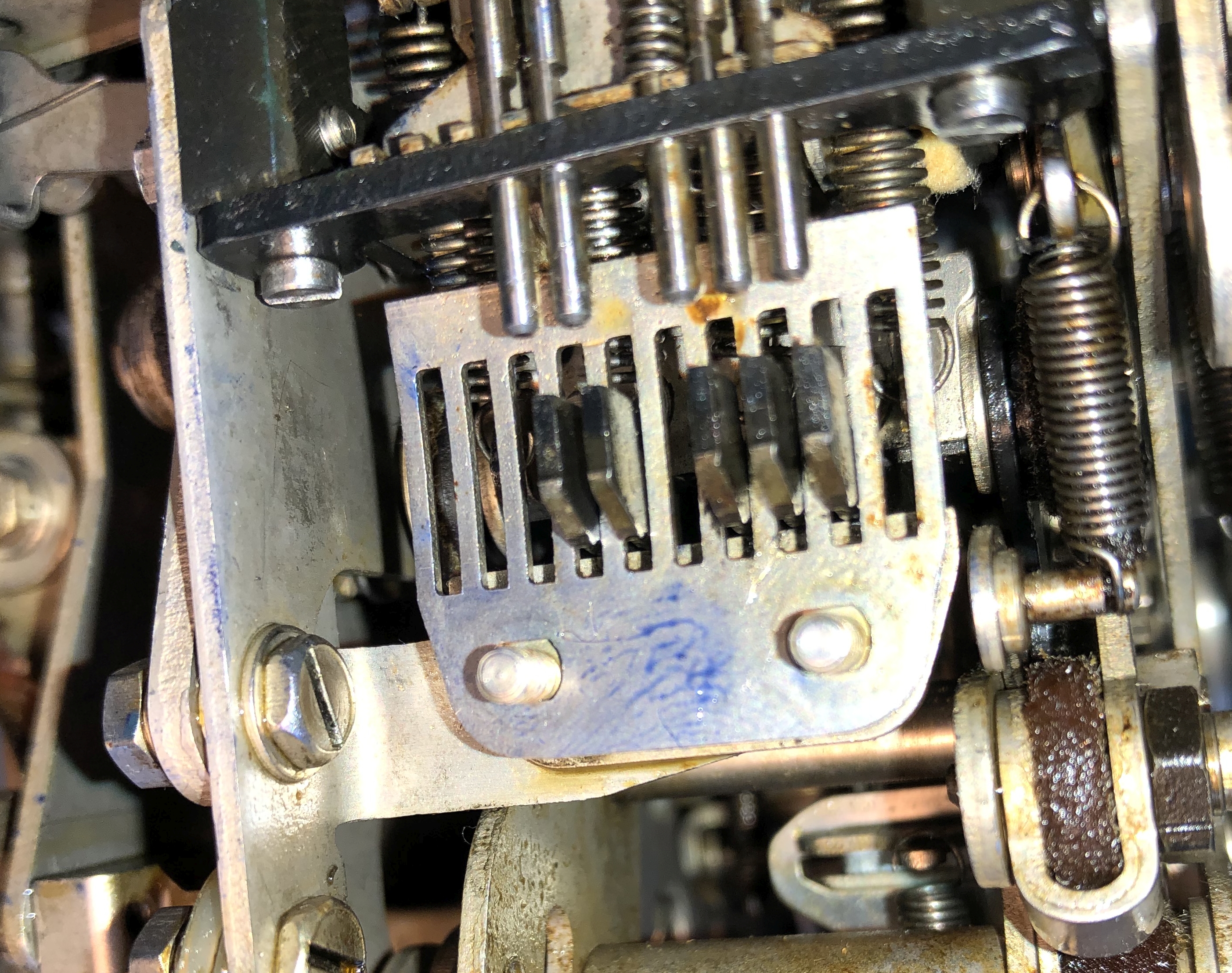 |
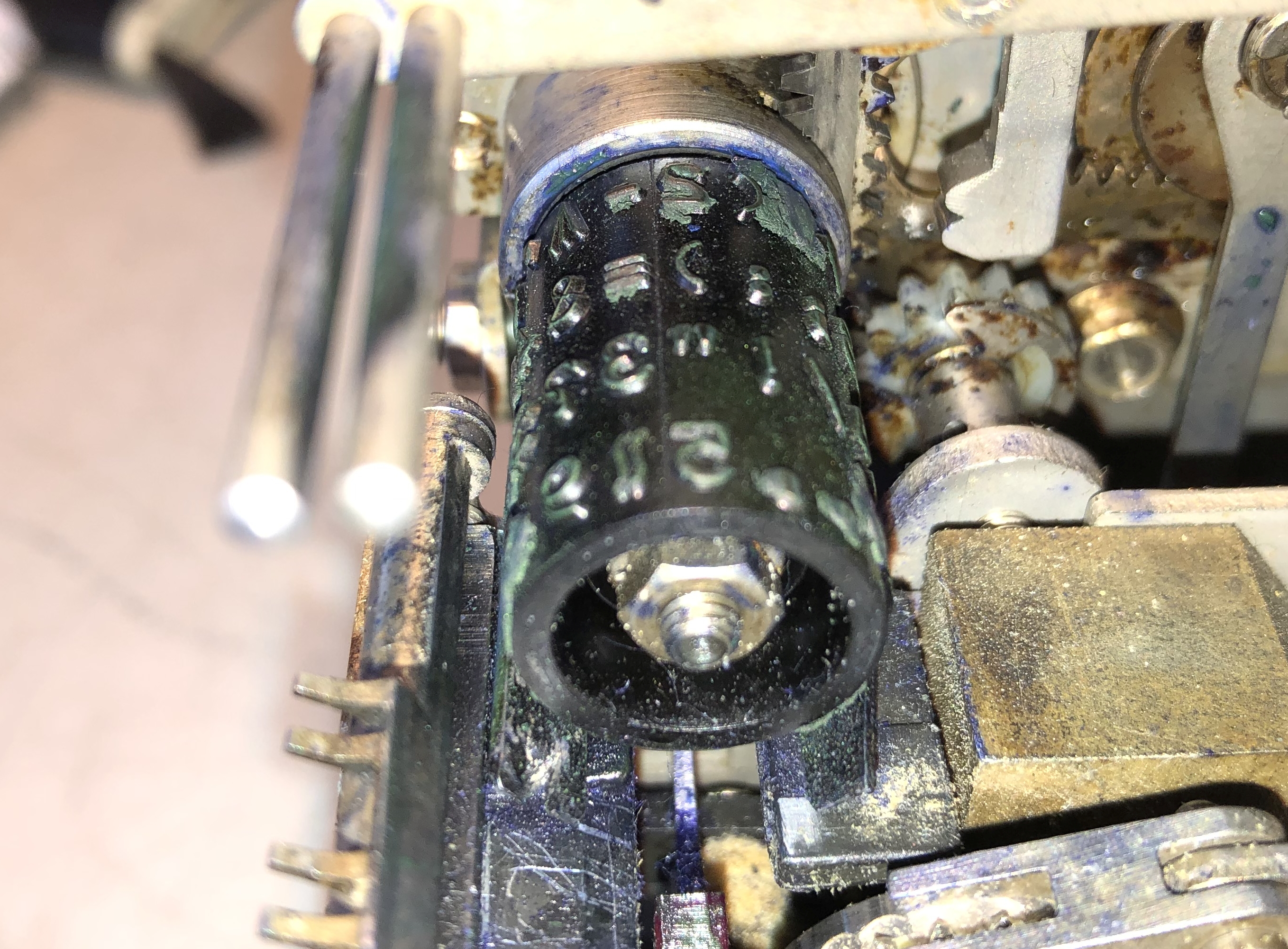
| IF you decide to remove and clean your typewheel, here are two suggestions | |||
| 1. Make note of the wheel position. "5" is up when at rest in LTRS mode. It rotates slightly clockwise to print the "null" symbol || . 2. To realign see adjustments below
|
HINT -Wear latex gloves unless you want
permanent proof that you have removed
lots of old ink from the typewheel.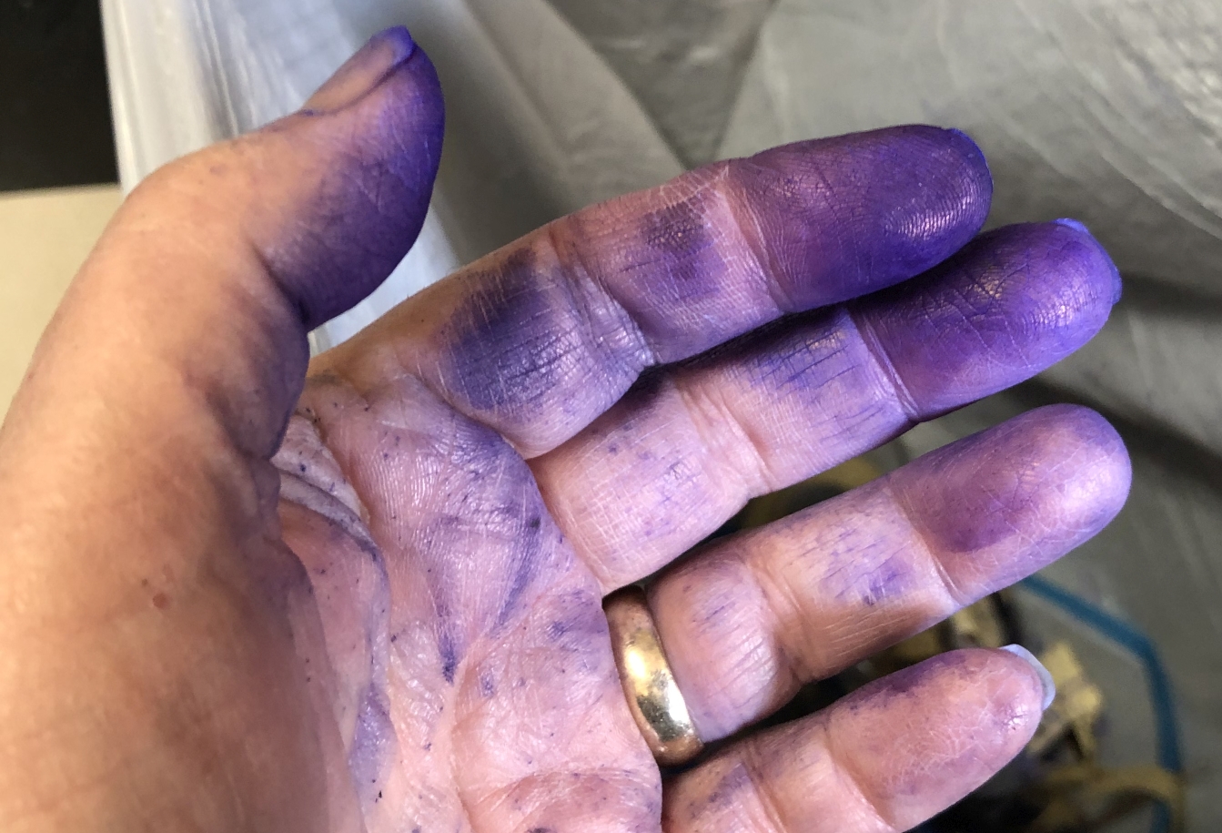 |
== |
== |
MANUALS - ADJUSTMENTS - PARTS - THEORY OF OPERATION |
|||
Adjustments - If you haven't removed the typewheel, then you should be OK. Otherwise you may need to loosen and rotate the typewheel on
its shaft. |
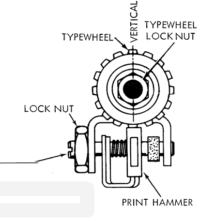
If the hammer is off to one side and not hitting squarely, Read
page 65
|
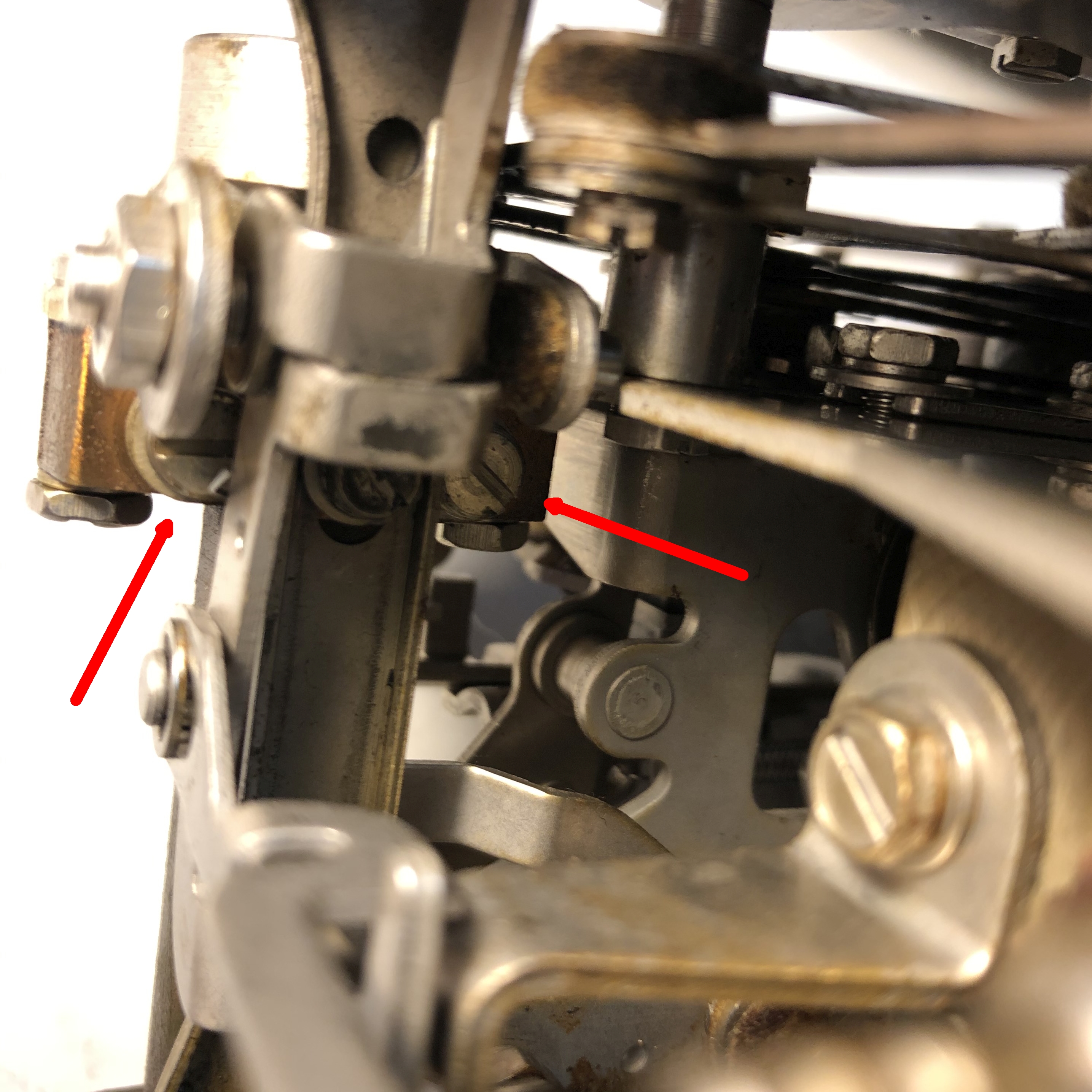
UNLIKELY - but if you need to move the hammer in/out a
little, you can loosen the two screws holding the bottom of the hammer
lever plus ribbon guide assembly and reposition the assembly. See photo at
right >>>>
ALSO NOTE - there is supposed to be a spacer in the rear of the typewheel - if that has been lost, the printing may be too far toward the edge of the tape. See Parts book page 10 |
|