From "Evolution of Naval Radio-Electronics and Contributions of the Naval Research Laboratory" (Gebhard) - 25MB pdf
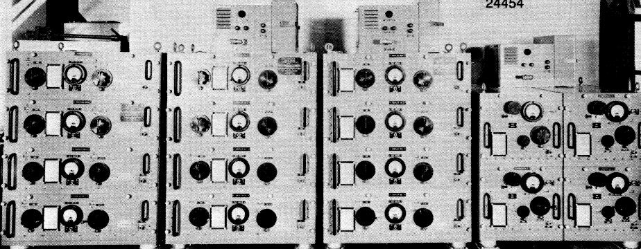
HIGH FREQUENCY TRANSMITTER MULTICOUPLERS
These multicouplers incorporating an NRL-developed technique were first to
permit simultaneous operation of four transmitters on a common antenna (1959). They provided frequency
channel isolation of 20 dB at 10 percent frequency separation. In 1964 they were modified by NRL
to permit the operation of eight transmitters with 40 dB isolation at 5 percent frequency
separation. Left to right are the Models AN/SRA-13, 14, 15, and 16.
Transmitter Multiplexing
The transmitter multiplexing problem is particularly critical, since high power in coupling circuit components is attended with the generation of heat, which may be difficult to dissipate, and high voltage, which may cause breakdown. Early work on this problem resulted in a
filter technique which permitted the operation of three lower frequency transmitters on
one antenna for the first time (1922). This technique was first applied to the high-frequency band using the Models TU (200 to 400 kHz) and
TAF (2 to 18.1 MHz) transmitters (1930). It was demonstrated on the USS TEXAS with the Models TO (0.5 to 1.5 MHz) and TV (2 to 3 MHz) transmitters (1930) and applied later on the USS SARATOGA and USS DETROIT
(1931). The technique was incorporated in the Model XZ antenna diplex coupling system and applied to other ships (1932). The technique, however, required quite wide separation between frequency channels and had high efficiency only for the lower frequency transmitter. Because of complexity in making adjustments, it was limited in use to two transmitters on a common antenna in shipboard applications.
In later work, the Laboratory was first to devise a transmission line-series coupling technique by means of which transmitters were coupled at intervals along a concentric transmission line to its inner conductor through small openings in its outer conductor (1946) Antenna multicouplers employing this technique became standard equipment in a variety of shipboard installations (AN/SRA-13, 14, 15, 16). For the high-frequency band, low-loss resonant circuits connected to the transmitter were arranged to couple to loops inserted in series with the inner conductor of the transmission line. With this technique, four high-frequency transmitters could be operated on a common antenna with a frequency separation of 10 percent, an isolation of 20 dB, and a nominal power loss of 1 dB (1950). This isolation was adequate to prevent interaction between transmitters. Multicouplers incorporating the transmission-line coupling technique were first installed on the submarine USS IREX using three high-frequency transmitters (1950). An extensive installation of multicouplers employing the technique was made on the USS NORTHAMPTON (1953). These couplers permitted the use of four transmitters on each of five broadband antennas and gave coverage of the entire high-frequency band.
A serious difficulty was encountered in determining adjustments which would provide proper impedance match between the transmitters and the antenna. This problem was solved by devising a reflectometer which was inserted in each of the transmission lines connecting the transmitters to their respective coupling units (1947). This reflectometer comprised a short wire placed parallel and close to the inner conductor of the transmission line. The wire was arranged so that the voltages caused in it due to inductive and capacitive couplings by the outward flowing energy were balanced. This device permitted sensing the reflected energy, which was of reversed phase with the inductive coupling but not with the capacitive coupling. A microammeter and diode connected to the short wire permitted observation of the amount of reflected energy and adjustment of impedance to reduce this energy to a minimum.
Voltage breakdown between the surfaces of variable air capacitors used to tune the resonant circuits of multicouplers was a further difficulty encountered in their development. The spacing of the surfaces could not be increased without increasing physical size beyond that permissible at the operating frequency. To overcome this difficulty NRL, with the cooperation of a contractor (Jennings Co.), developed a high-power, vacuum variable capacitor using a bellows mechanism to provide the variation of capacitance without disturbing the vacuum seal (1949). This structure permitted close spacing of surfaces with corresponding compactness and a capability of withstanding high voltage. The surfaces of the capacitor were so contoured as to minimize losses. This vacuum type of variable capacitor was first used in the high-frequency multicoupler of the USS NORTHAMPTON installation (previously described) at a 1/2-kW power level. A capacitor of further improved design was included in the NRL-developed multicoupler AN/FRA-49 (V) which permitted operation, for the first time, at the 10-kW level in the 2 to 6 and 5 to 15 MHz bands. This type of multicoupler was first installed at the Naval Radio Station, Annapolis, Maryland, where three l0-kW transmitters were operated on one antenna (1956). Subsequently, it was installed at other shore stations. A 10-kW multicoupler capability in the 10 to 30 MHz band was first attained by employing a coaxial transmission line type of resonator in combination with the new capacitor. This capability was first provided the communication ship USS ANNAPOLIS (1964). The vacuum variable capacitor found wide use in various applications.
Doubling the number of transmitters which could be operated on a common antenna was made possible through NRL's development of a multicoupler with dual-mesh resonant circuitry and a combining network which provides impedance compensation (1959). With this new multicoupler, eight transmitters could be accommodated on one antenna The isolation between channels was also doubled to 40 dB, with a frequency separation of 5 percent. The insertion loss was nominally 2 dB. Previously developed multicouplers AN/SRA-13 and AN/SRA-14 (1/2 kW) were modified to include this new combining circuitry to obtain the eight-channel performance. Initial installations of these were made on board the USS ESTES (AN/SRA14) (1964) and the USS NORTHAMPTON (AN/ SRA-13) (1965). Ten-kilowatt multicouplers resulting from this work (AN/SRA-35, 36, 37) were procured (Naval Gun Factory, Washington, D.C.) and first installed on the communications ships USS WRIGHT (CC-2) (1963). The AN/SRA-56, 57, and 58 multicouplers for 1-kW operation utilized the new circuitry, which was useful in multicoupler design.