NAA Cutler Maine - Navy VLF Transmitter Site
2 MW, 14-24 kc
Check out Bill Heidig's photos of Cutler -
here's a sample
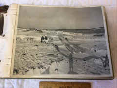
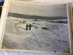
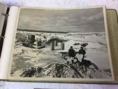
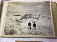
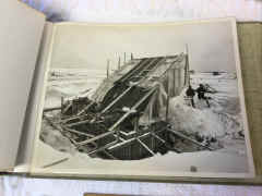
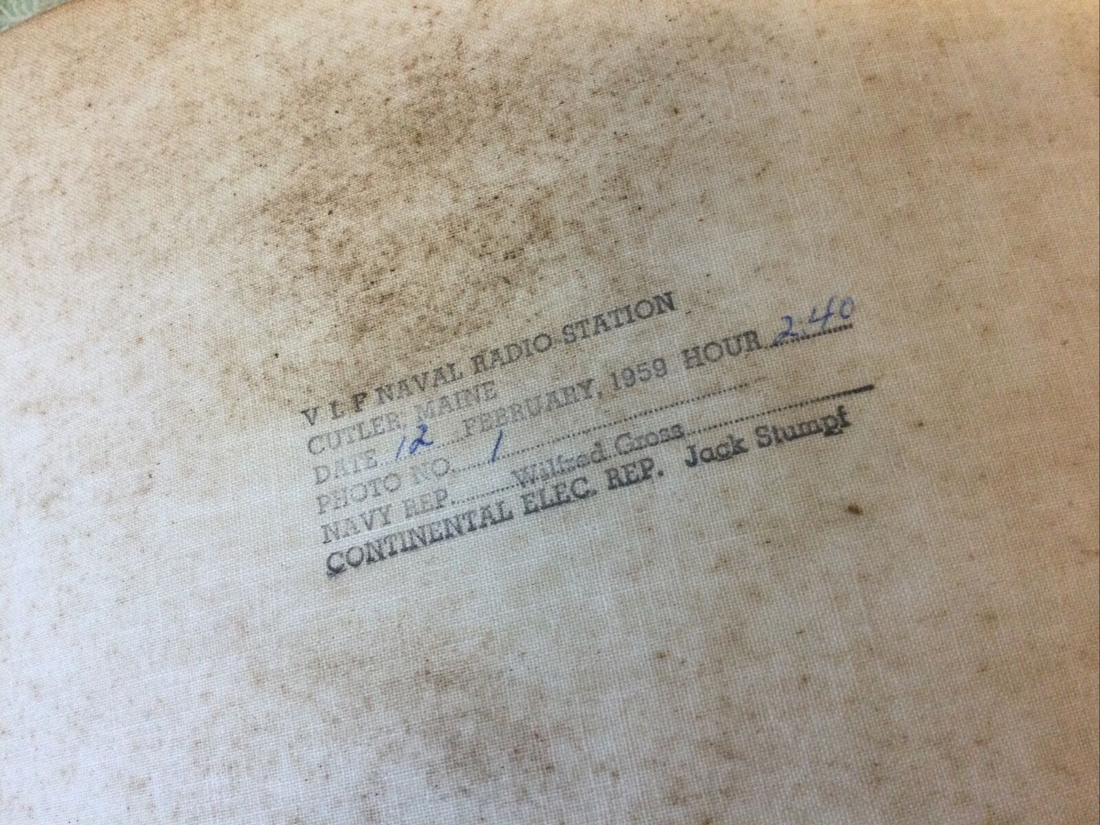
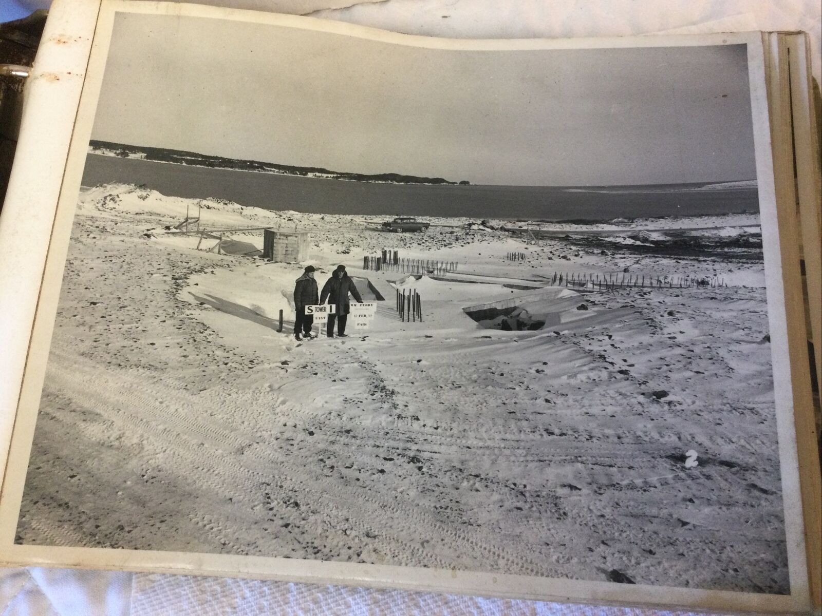
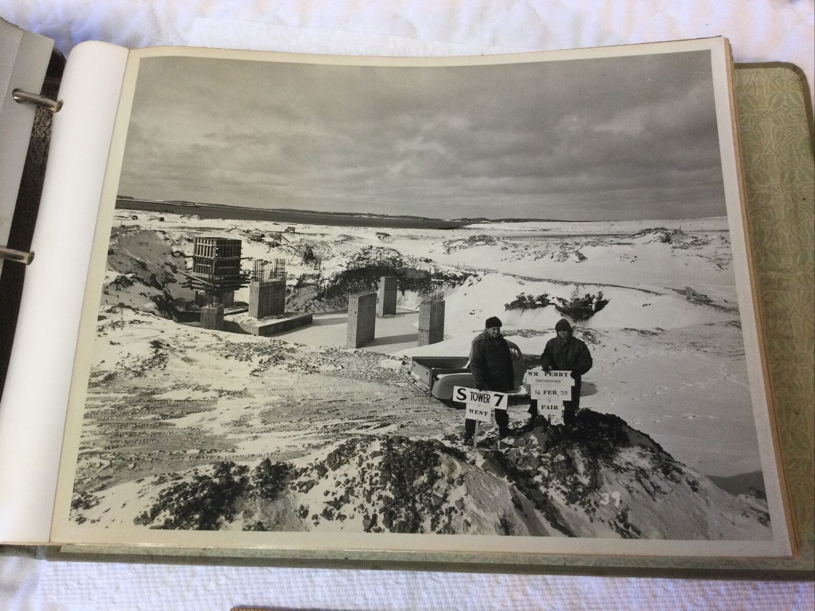
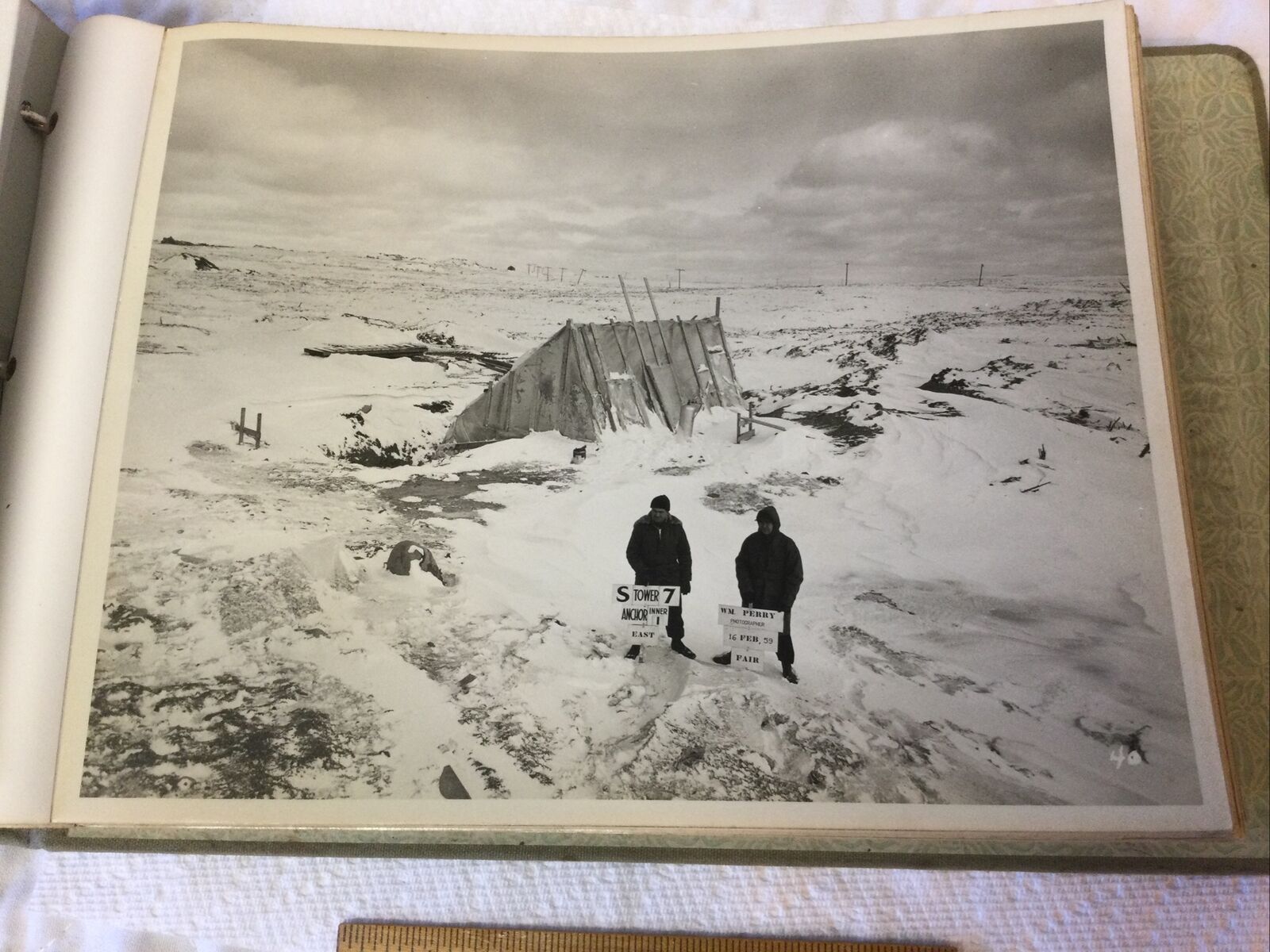
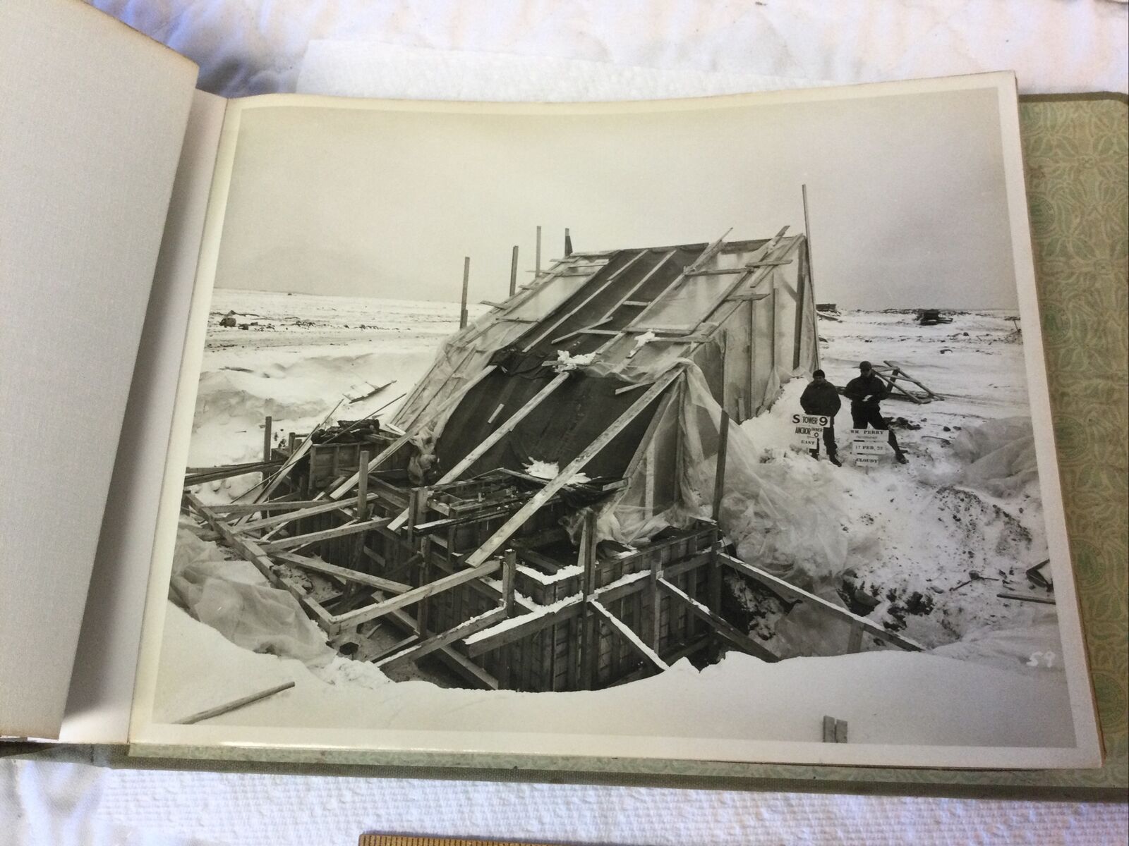
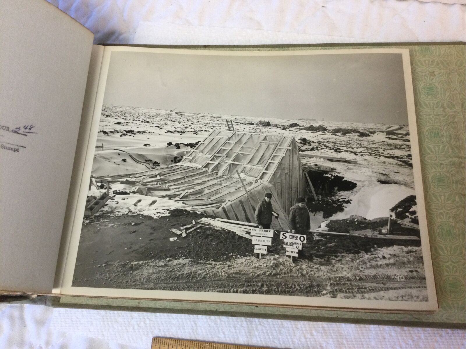
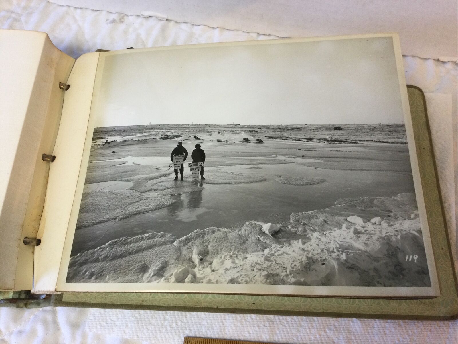
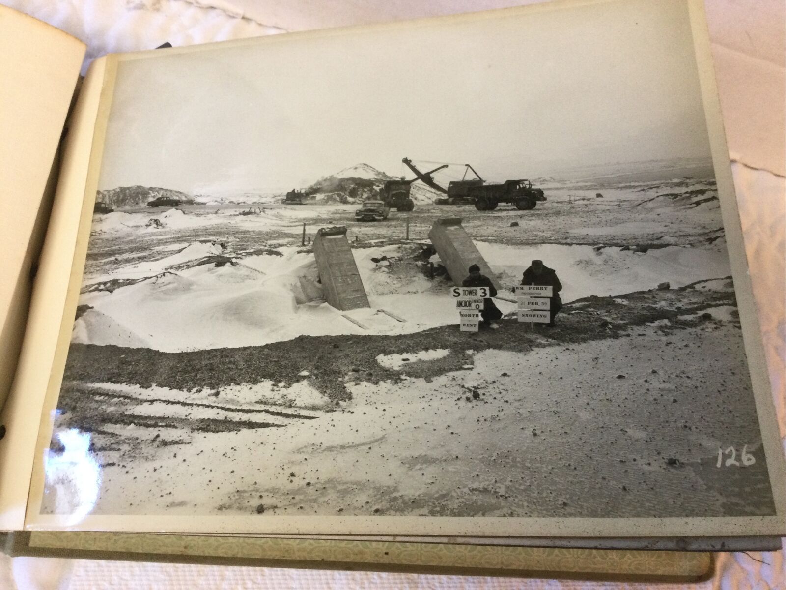
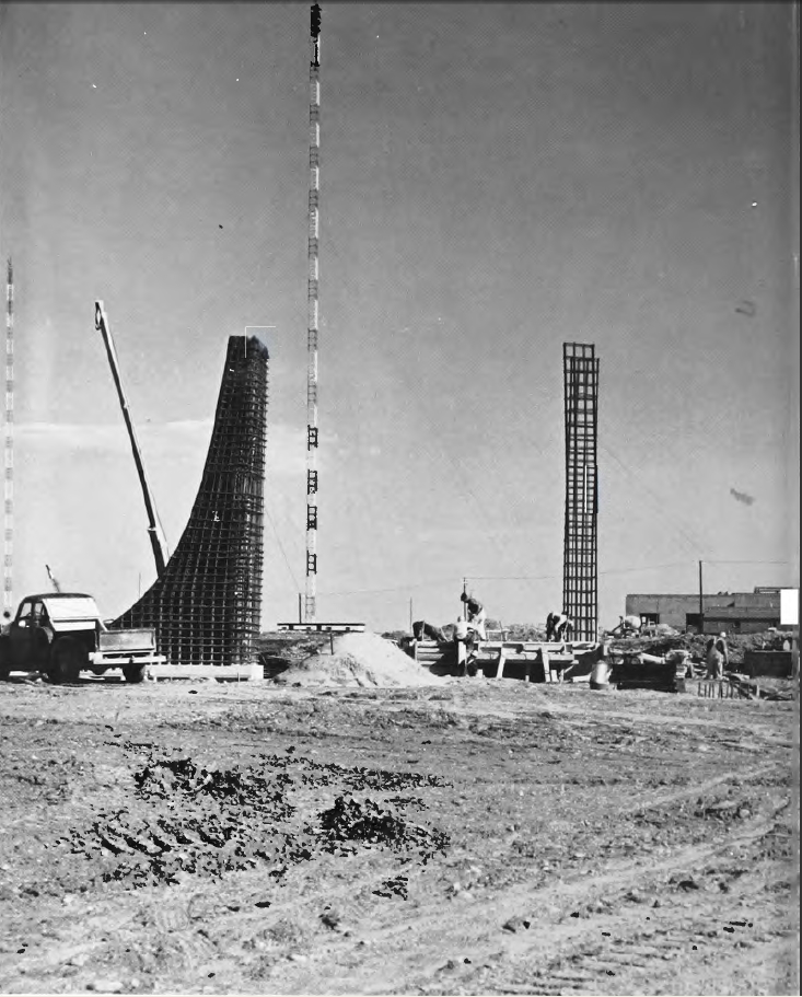
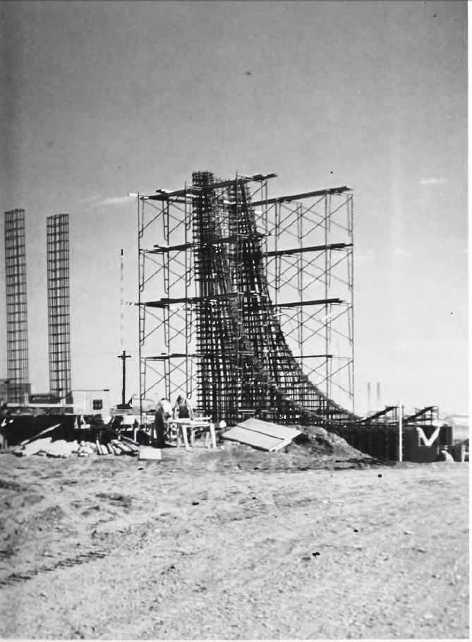
February 1959 Construction Photos

|
 |
 |
 |
 |
 |
 |
 |
 |
VLF Maine - BuShips Journal February 1960
An unusual and gigantic radio transmitting station is under construction at Cutler, Maine. The station
will extend the worldwide U.S. naval communication system and will transmit on VLF (very low frequency)
to the Fleet, including the Polaris FBM (fleet ballistic missile) system, and to other submerged submarines
when operating in the Atlantic and Arctic Ocean regions.
The threat of enemy jamming will be offset by unprecedented signal power, use of
the VLF bands, and by alternate stations, frequencies, and signaling systems in the program.
The VLF Maine project was initiated as a normal addition to the naval communications system shore
facilities. However, its usefulness in the Polaris missile system changed the urgency and resulted in an
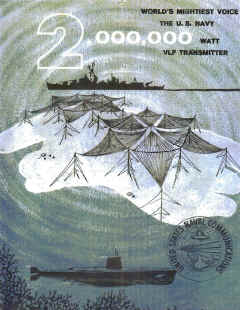
acceleration of funding to expedite its construction. The transmitter has a nominal output power of
2,000,000 watts, or 40 times the power of any major commercial radio broadcasting station. At the
expected antenna efficiency, the radiated power will be 1,000,000 watts.
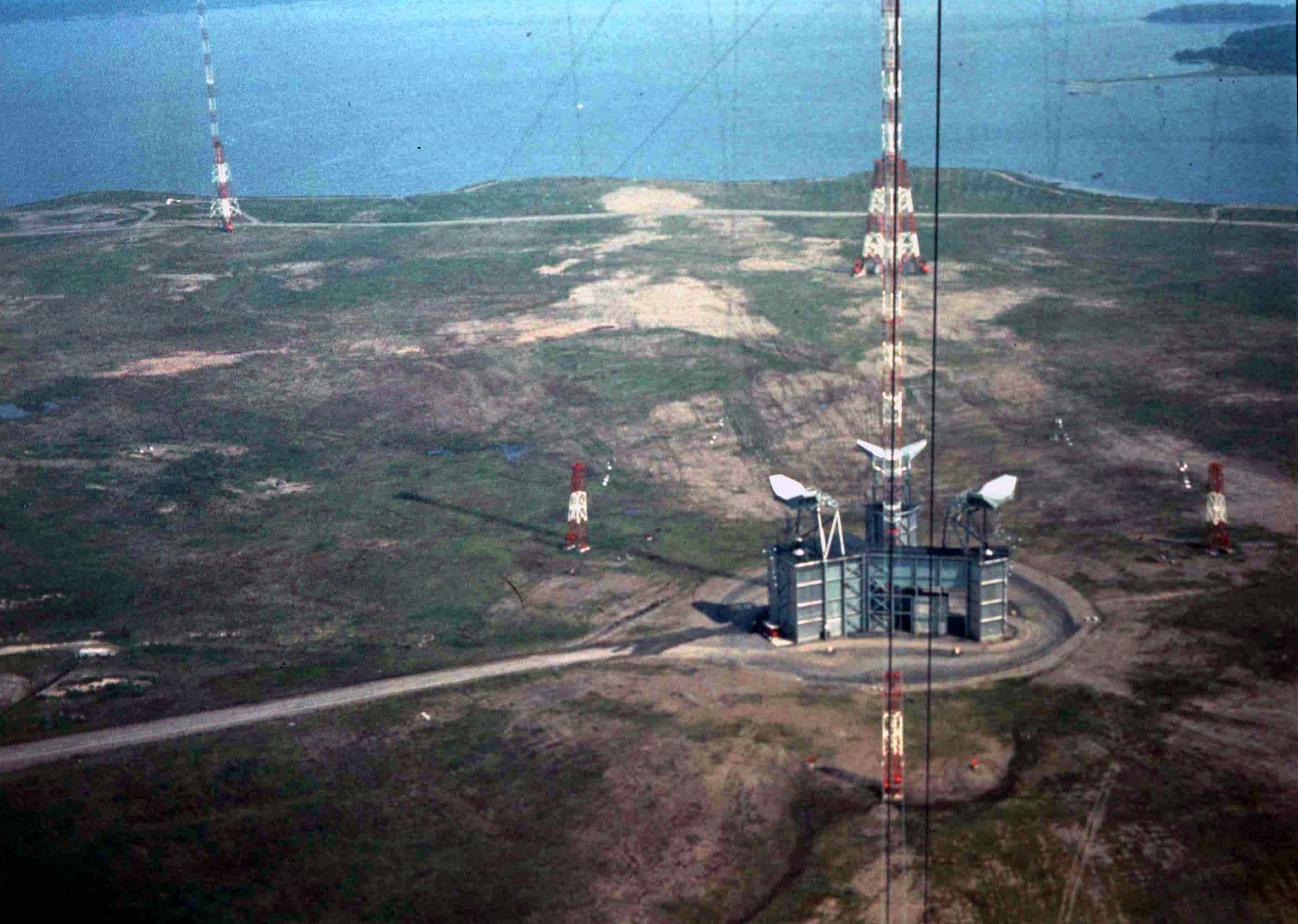
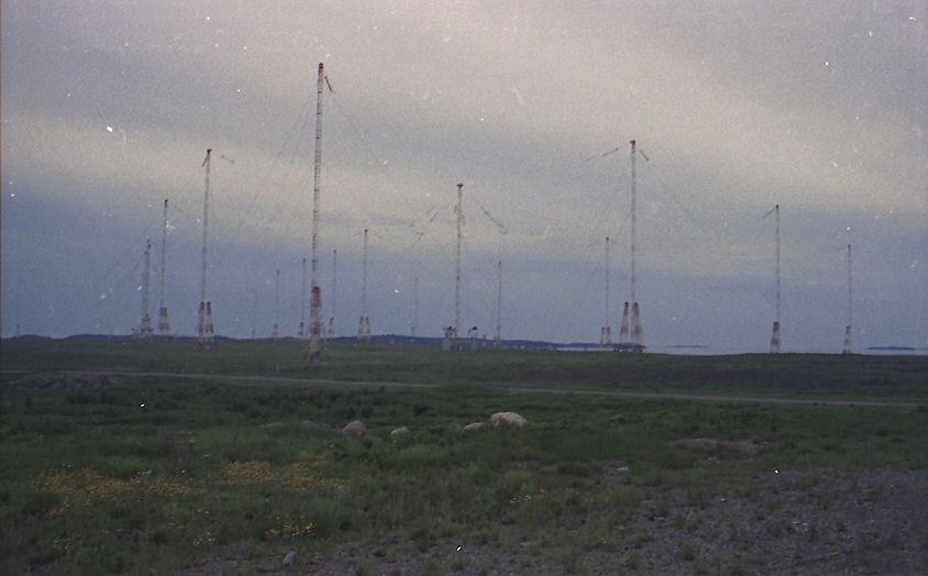
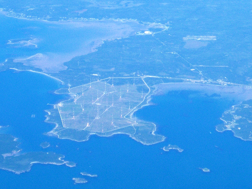
VLF Maine will be the largest and most powerful facility of its kind in the world when it is completed
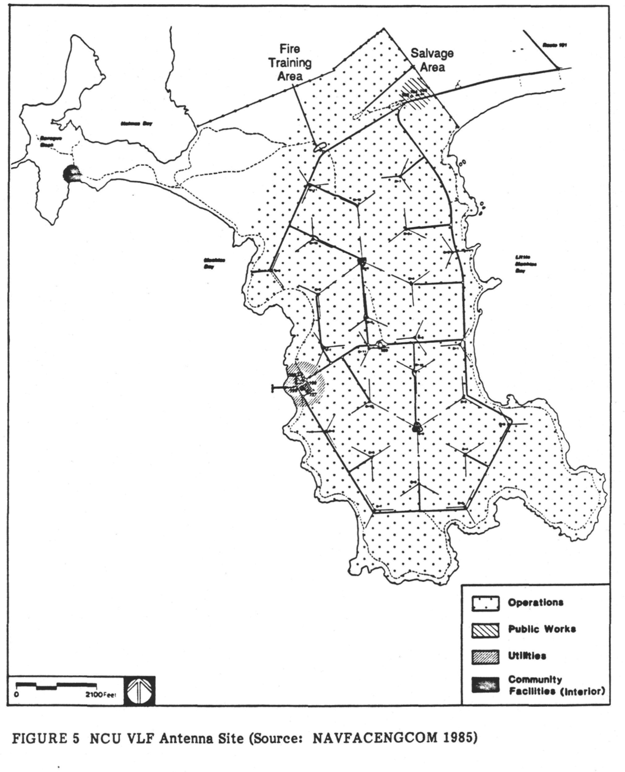
about January 1961. It will cover a peninsula of nearly 3,000 acres on the Maine coast at Machias
Bay. At the present time the sit has been cleared and construction of the buildings and the erection of the
antenna towers are in progress.
The vast acreage is required for the large antenna and extensive ground systems that are
necessary for efficient radiation of very low frequencies, and only VLF will penetrate the sea to a sufficient
depth to allow submerged reception of the signals. Meteorological factors entered into the design of
the antenna, too. The structures are designed to withstand winds of 150 knots and ice accumulation on the
antennas and towers to a radius of 3 inches. 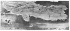
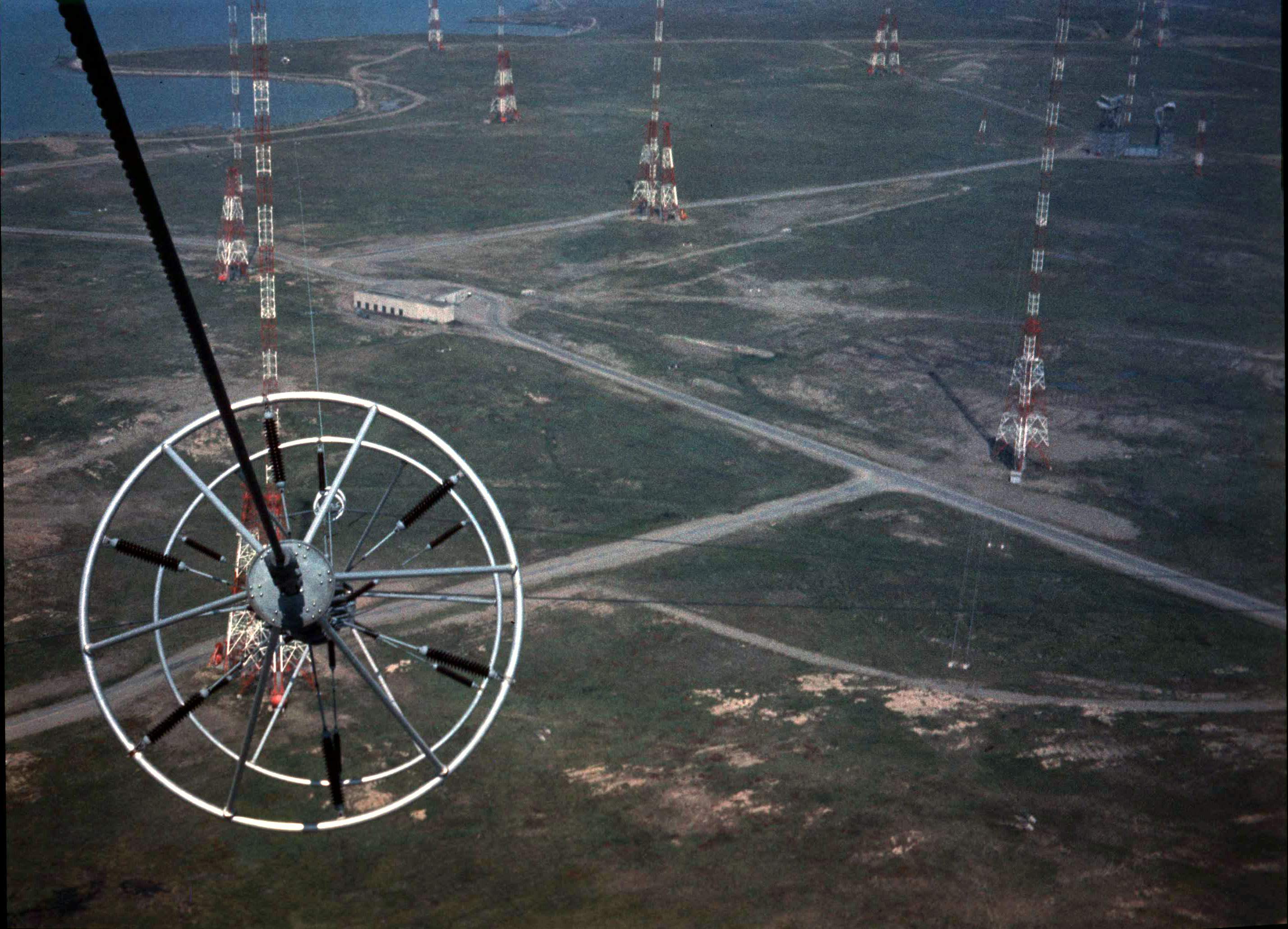
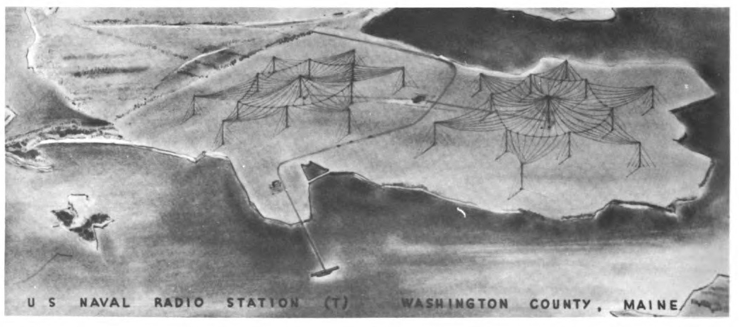
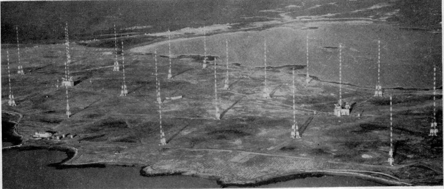
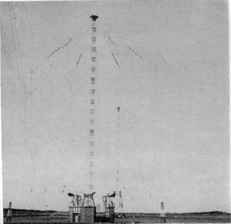
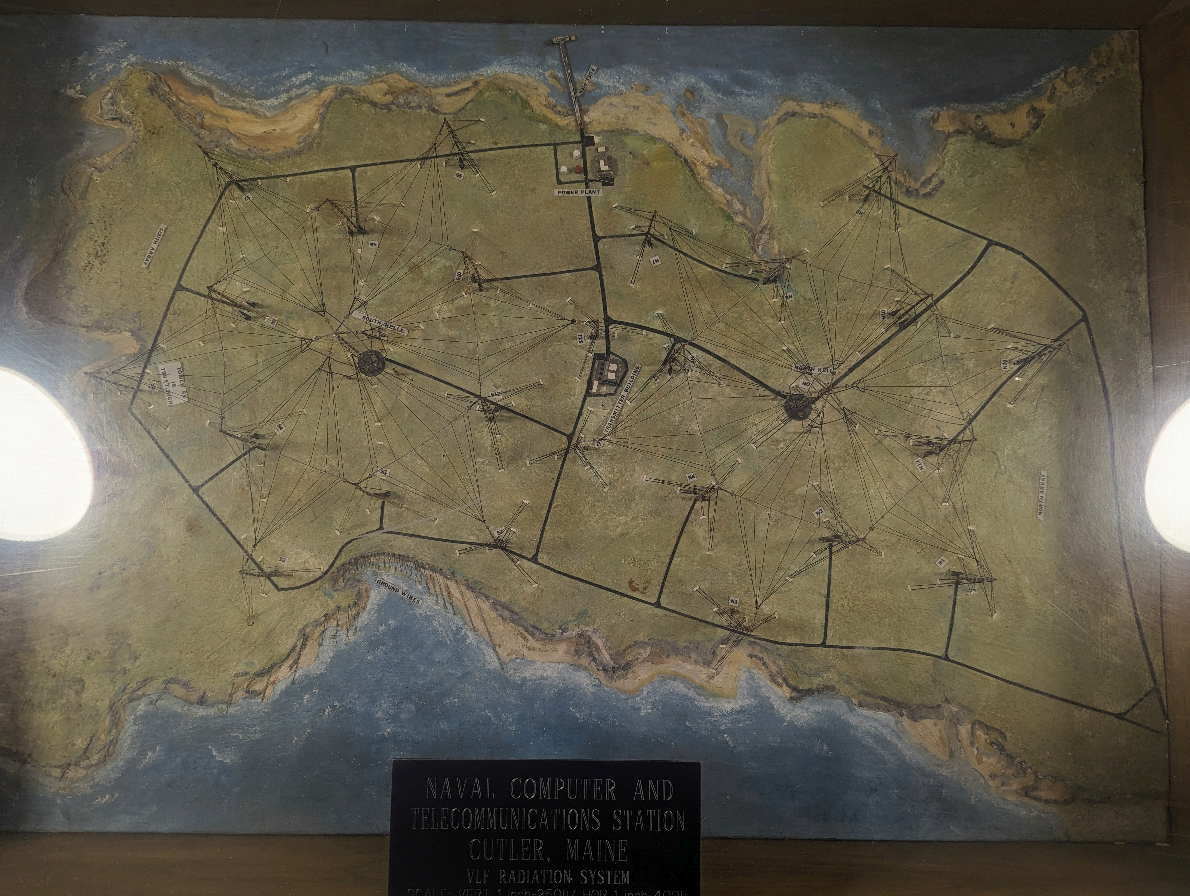
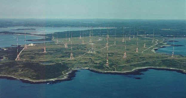
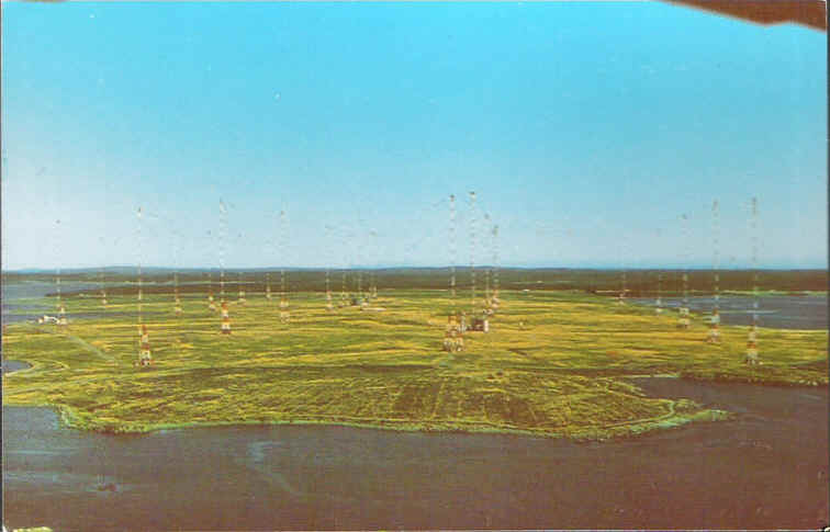
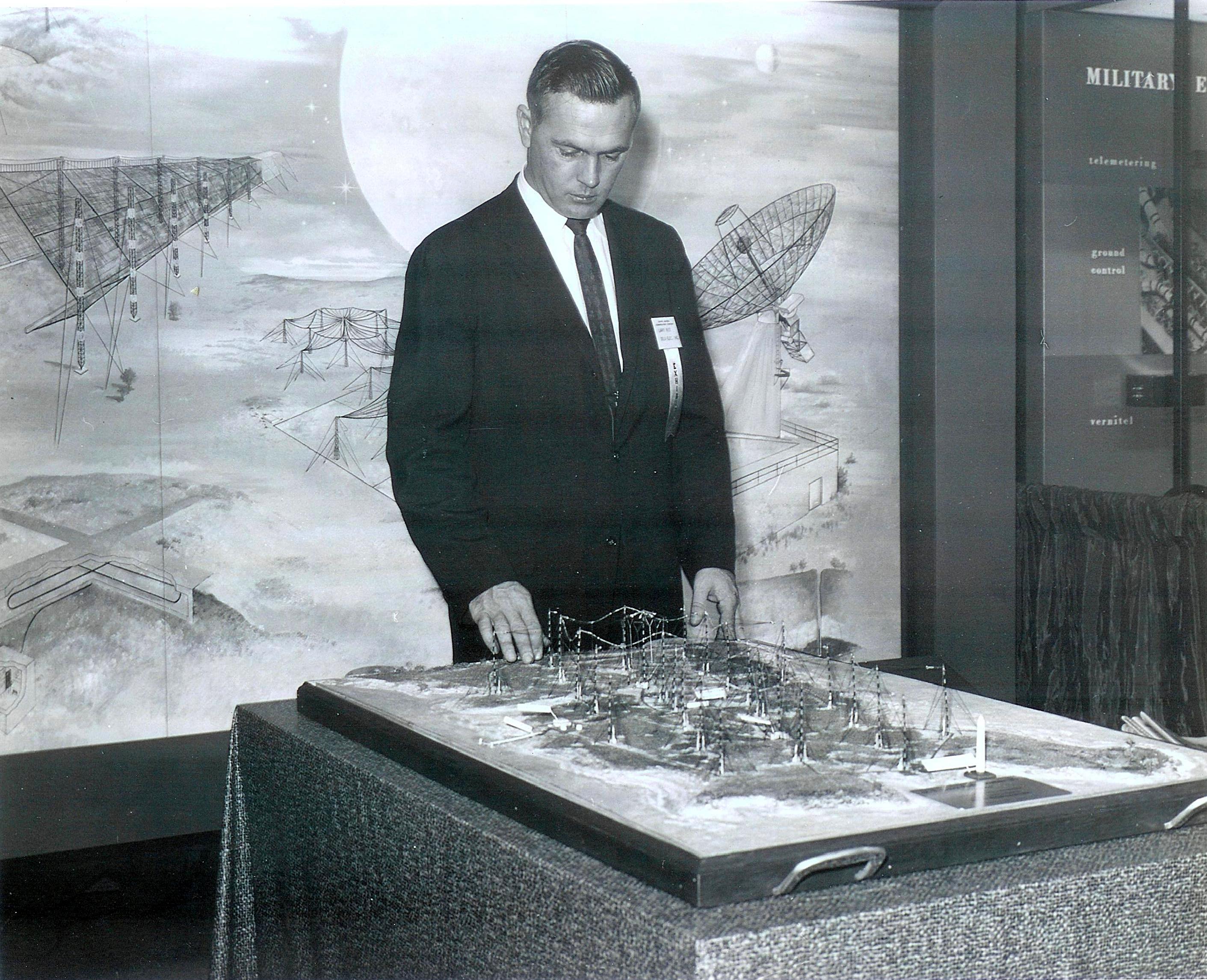
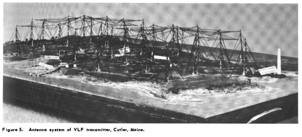
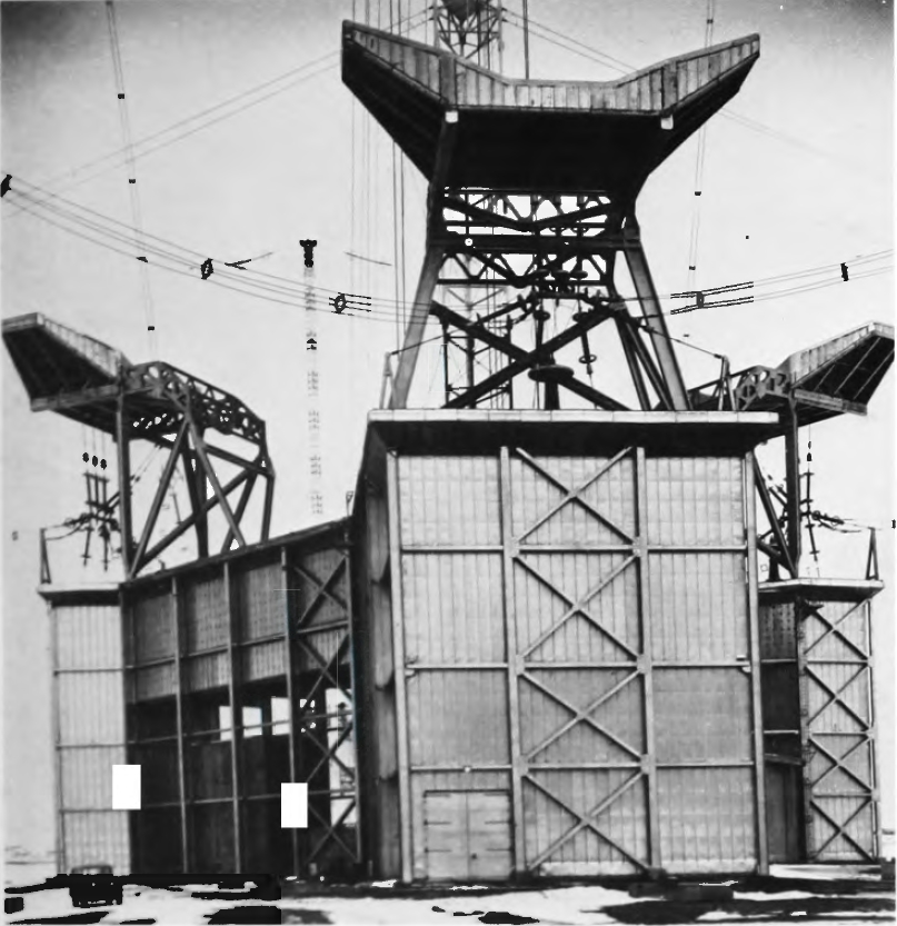
As can be seen in the accompanying figure, the
antenna will look like two giant six-pointed stars. From point to point, the distance is 6,200 feet. Each
half of the antenna will cover an area equal to 11 Pentagon buildings!
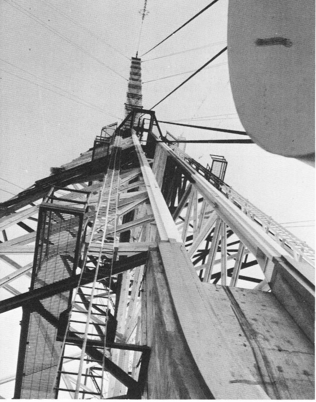
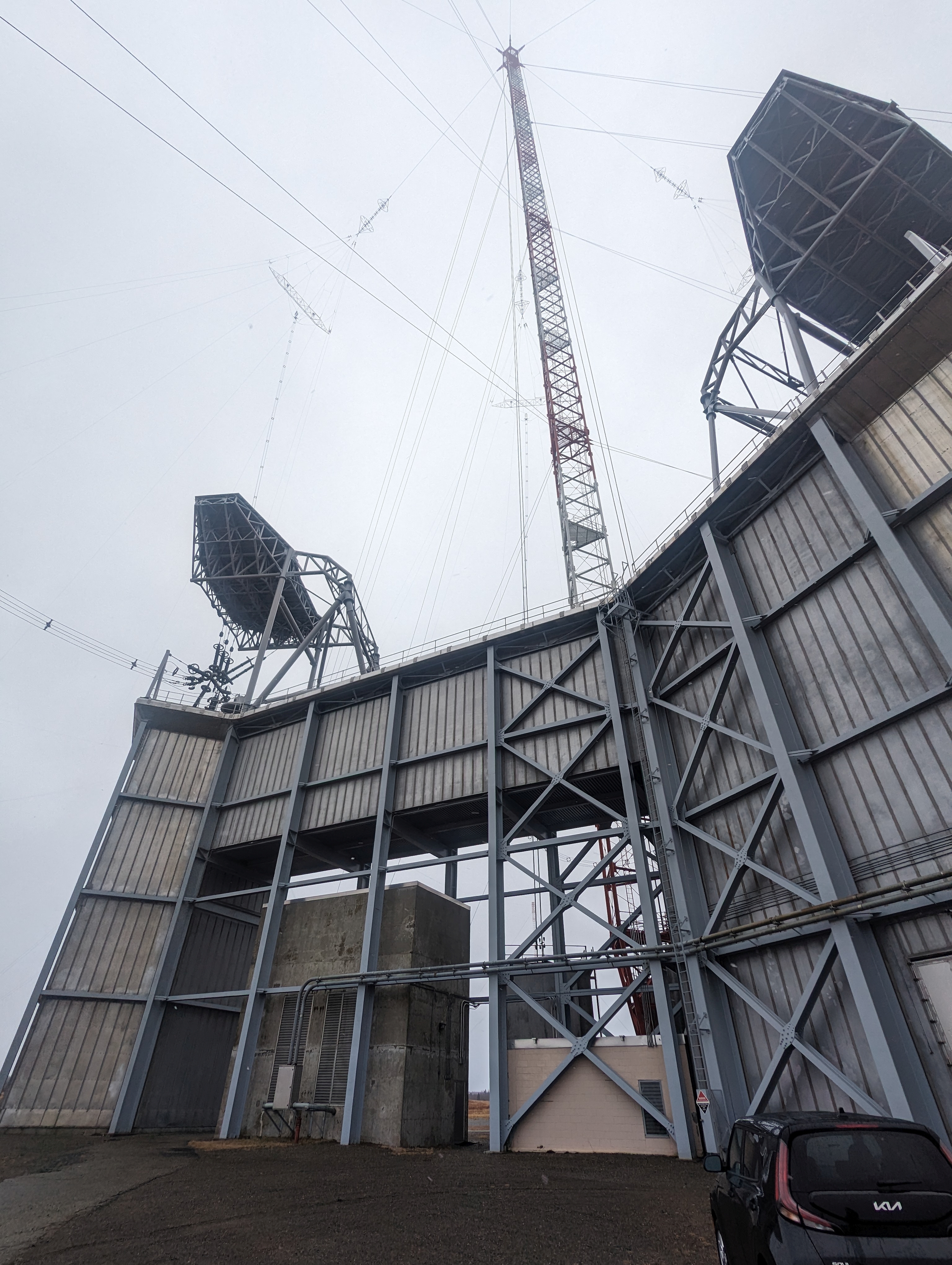
The antenna array is to be supported by 26 towers. In each half of the array there will be—
• A central tower, 980 feet high.
• Six intermediate towers, each 875 feet high.
• Six outer towers, each 800 feet high.
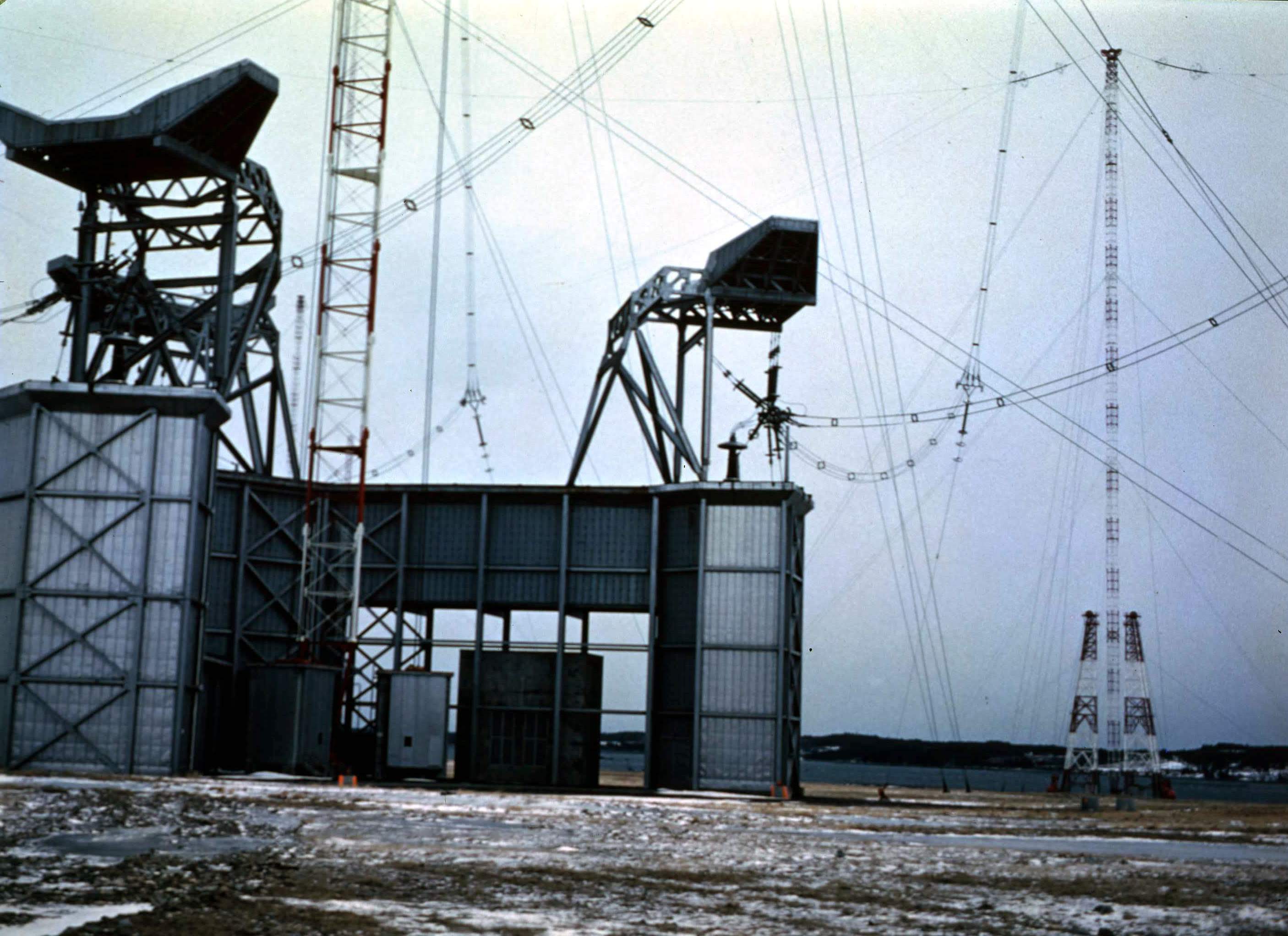
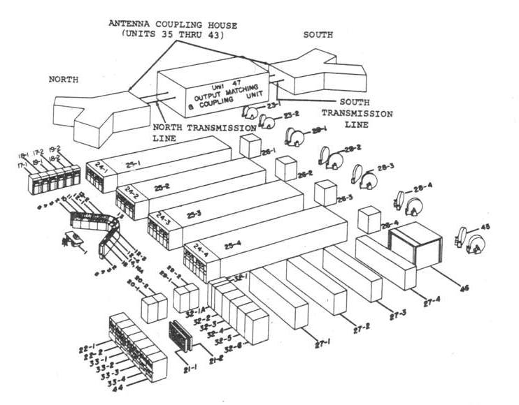
Midway between the two halves of the antenna will be the transmitter building, a structure with 25,000
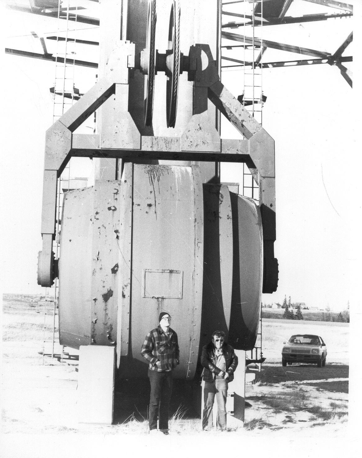
square feet of floor space. At the base of each central tower will be a smaller building, called the "helix
house," which will contain the antenna tuning and coupling components and de-icing switch gear.
The transmitter has four final amplifier units, of 500 kilowatts each, the outputs of which will be
combined for full output. Any combination of the four units and the two halves of the antenna is possible, so there
will be full flexibility of output, and maximum ease of maintenance. Transfer of power from
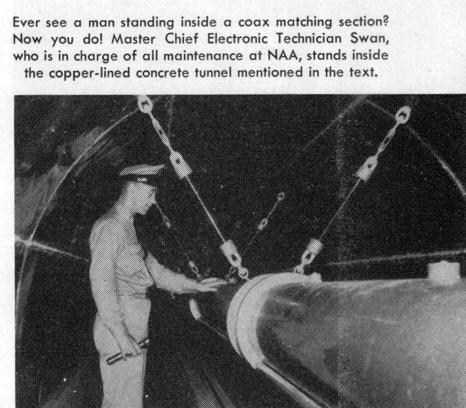
the amplifiers to the helix houses will be by way of large coaxial cables in tunnels.
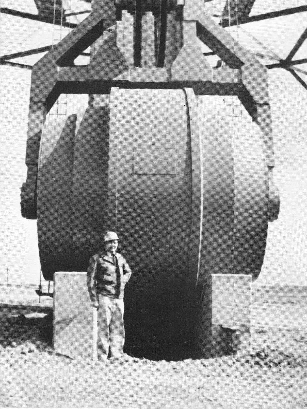
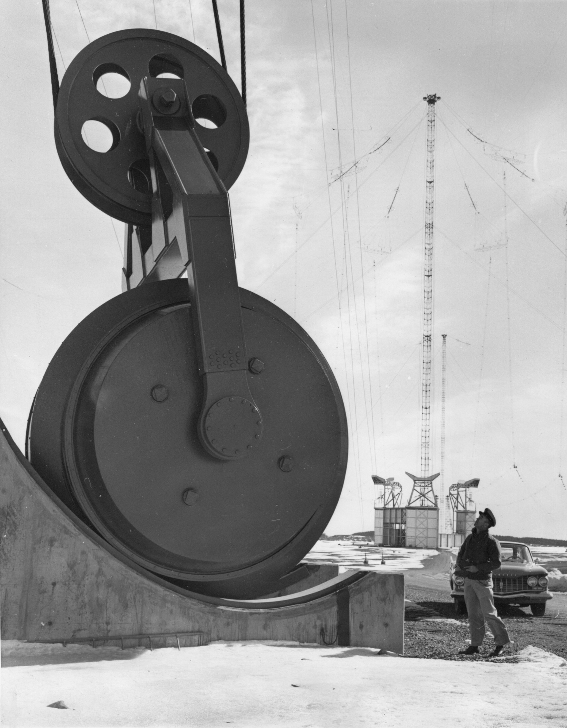
Each antenna panel will be counter-weighted at all supporting towers except the center one. These
weights will roll on stub towers beside die main towers. The maximum tension on each halyard, at peak
wind load, will be 110,000 pounds.
Electric hoists at each tower make it possible to lower and raise each panel individually for
maintenance. The panels can be switched onto a de-icing circuit capable of freeing the wires of 3-inch radial ice.
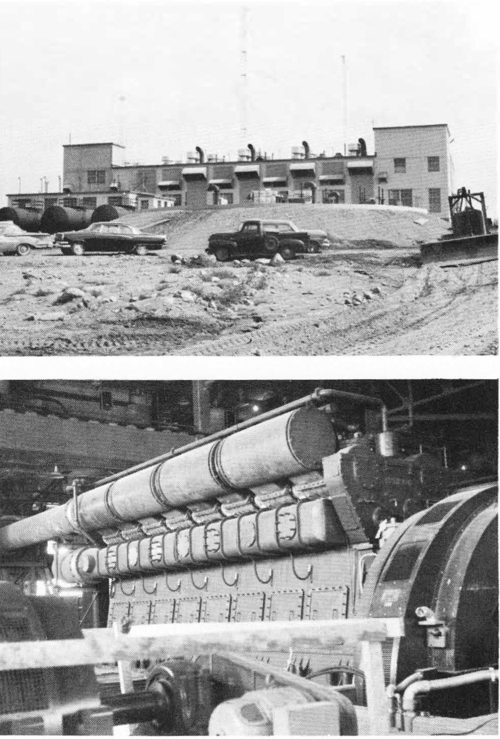
Diesel engine-driven generators will furnish 11,000 kilowatts for operation of the station, including the
transmitter, station lighting and power, electric hoists, tower lighting, and the de-icing circuits.
A large and elaborate system of buried ground wires will collect the RF displacement currents and
return them to the helix houses. Since earth is a relatively poor electrical conductor, and sea water is a
very good conductor, the ground system will consist of buried copper wires, radiating from the array centers to
the sea water which surrounds the peninsula on three sides. Over 2,000 miles of number 6 copper wire will
be used, with as many as six radials per degree in some areas, and with special foundations and guy anchors.
The Bureau of Ships and the Bureau of Yards and Docks are cooperating in the construction of VLF
Maine, as is customary when shore communication facilities are built. Normally, the Bureau of Yards and
Docks expends the MCON funds directly for the architectural and engineering design and for the
construction of the facilities, with only "technical collateral" funds in the amount required for the procurement
and installation of electronic equipment being allocated to the Bureau of Ships and its field activities.
However, in this case, the Bureau of Ships obtained Bureau of Yards and Docks authorization to
contract with an electronic manufacturing firm for an on-the-air station. The Bureau of Ships awarded contract
NObsr 71360 to Continental Electronics Manufacturing Company, of Dallas, Tex., for an engineering site
survey, the electrical and structural design of the antenna, ground system and power plant, and the design,
construction, and installation of the VLF transmitter. Additional options in this contract were cancelled and
combined in another contract, NObsr 75244, making Continental the prime contractor for the construction of
the following subcontract packages—
• Foundations and anchorages for towers.
• Tower and guy procurement and erection.
• Antenna procurement and erection.
• 11,000 kw power plant.
• Ground system fabrication and installation.
• Proof of performance tests and measurements.
A notable feature of this contract is a warranty clause in which the contractor has accepted a liability
of a half million dollars in guarantee of meeting the performance requirement of 1,000,000 watts radiated
power.
The Bureau of Ships has designated the Public Works Officer of the First Naval District as the officer-in-charge of construction, NObsr 75244, for all
structural work. This officer is also administering Bureau of Yards and Docks contracts for associated work
which includes such things as—
• A fuel pier jutting into Machias Bay capable of accommodating sea-going tankers.
• A fuel depot and tank farm.
• The transmitter building.
• About 12 miles of roads.
• A self-contained 50- to 60-acre village to house the station force of 160 persons and dependents.
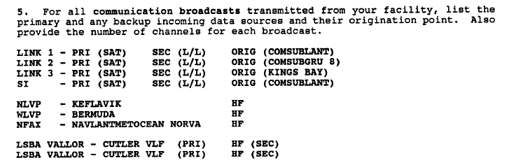
• A high-frequency station, to provide the high frequency components of the broadcast to supplement
the VLF.
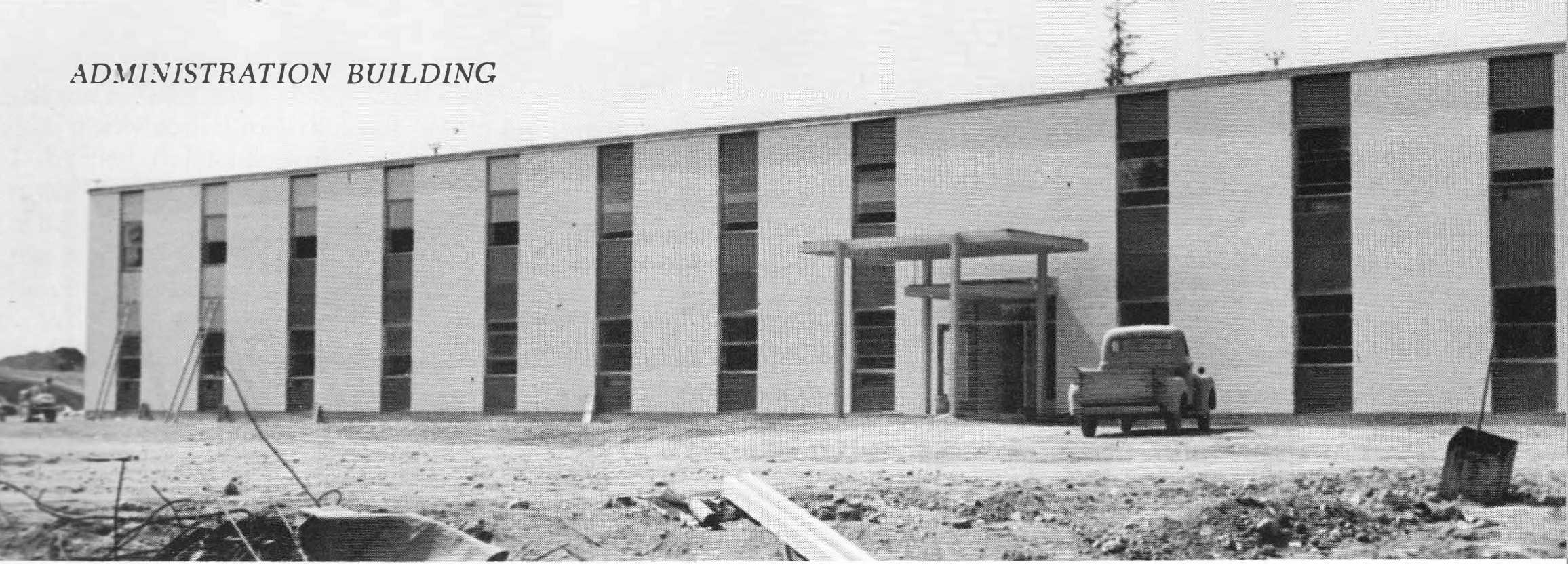
• Administration building, security fencing, gate house, and so forth.
|
From "All Hands" magazine December 1961 -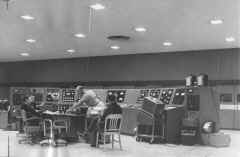
The U.S. Naval Radio Transmitting Station in Cutler, Maine, the Navy’s newest and most powerful radio transmitting station, and probably the most powerful radio station anywhere, is now open and doing an active business.
The new station, with rated power of more than 2,000,000 watts - 4 times more powerful than any transmitter in the United States - was completed one full year ahead of schedule. Cutler’s first greeting was beamed from its nearly 1000-foot towers on 4 Jan 1961 to Navy officials in Washington, D.C.
Once a remote wilderness, Cutler is located about 20 miles south of Eastport, Maine, the most northeasterly point in the United States. The station site is about 3000 acres, of which 2850 are devoted to the very low frequency transmitter and antenna site, and the remainder to the high frequency and administrative areas.
The Cutler site was selected primarily because the peninsula on which the station is now built is large enough to accommodate the antenna system of 26 towers in two separate arrays. Each consists of a central tower 980 feet high, six intermediate towers 875 feet high, and six outer towers 800 feet high. The two central towers are over a mile apart. Cutler is bounded on three sides by sea water, which was another major consideration in the selection of the site. Sea water is an excellent conductor of electricity and a vital element of the installation’s ground system.
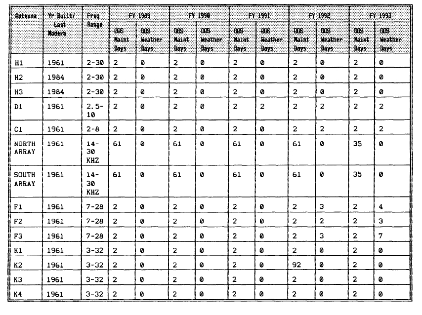
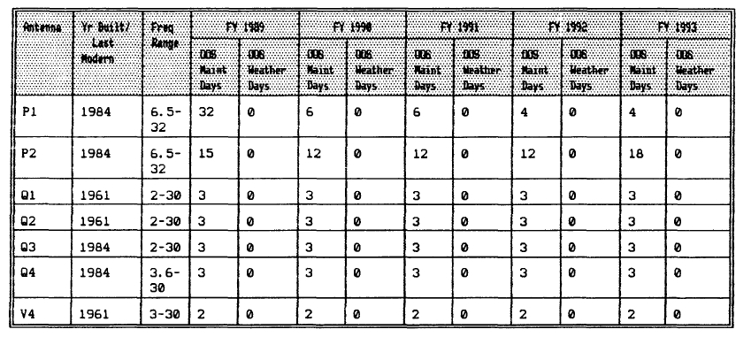
The mission of Cutler, with its superior communication facilities using both high and very low frequencies, is to provide adequate transmission to all units of the Fleet in the North Atlantic, Arctic Ocean, and Mediterranean waters. It will also be used for weather broadcasting, standard time and frequency broadcasts, and scientific investigation.
The Cutler project was started on 13 Jan 1958. During the peak period of construction, there were over 1500 persons employed. The core of Cutler is the reinforced concrete transmitter building, which has 25,000 square feet of floor space and is located midway between the two antenna arrays. Its power plant is capable of turning up in excess of 15 million watts for station demands and for VLF transmission. The station, however, will normally broadcast with two million watts.
During construction Cutler required 100,000 cubic yards of rock excavation; 2.5 million yards of earth excavation; 2800 acres of clearing and grubbing; 35,000 cubic yards of concrete for tower and anchor foundations; 12,000 tons of steel for towers; 3000 tons of steel bridge strand for guys and hoists; and 750,000 pounds of one-inch and 1-1/2-inch conductor wire. Further construction quantities include 2000 miles (1,000,000 pounds) of copper wire, which is buried 12 inches in the ground, and 40 miles of utility lines. The station also has 12 miles of roadways.
Weather should be no problem for the Cutler station. Although icing on the wires cannot be prevented, the wires will be able to withstand three inches of radial ice. And, even if the ice does reach this thickness, both groups of towers are e uipped with electrical de-icing circuits for melting the ice. One group can be de-icing while the other is operational. The towers will be able to withstand winds up to 175 knots.
Only two other naval VLF stations, one at Annapolis, Md., and the other at Jim Creek, Wash., are like Cutler, but neither can compare with Cutler in size or output. The Navy also has four other VLF transmitting stations.
The VLF radio station at Cutler cannot receive signals. The high frequency component, however, will have both transmitting and receiving facilities.
A generating plant aboard the station provides the power for Cutler. It can produce about 15,000 kilowatts, or enough to furnish all the electrical power for 37,000 families (based on the New England average). About 3,000,000 gallons of fuel will be used at Cutler annually.
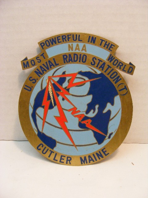
Historically, the Cutler Radio Station is a lineal descendent of the Navy’s first high-powered radio transmitting station located at Arlington, Va. The call letters at Arlington - NAA, - were known to naval and merchant radio operators the world over. It furnished continuous service from 1912 untiI it was supplanted by navy Radio Washington DC located at Annapolis Md.
Cutler has the historical radio call sign NAA. The VLF transmitter can send 25 words per minute on-off keying and 60 words per minute FSK (Frequency Shift Keying).
|
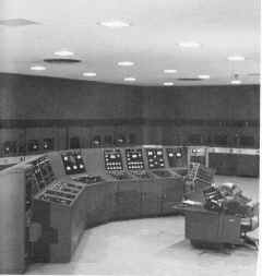
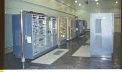
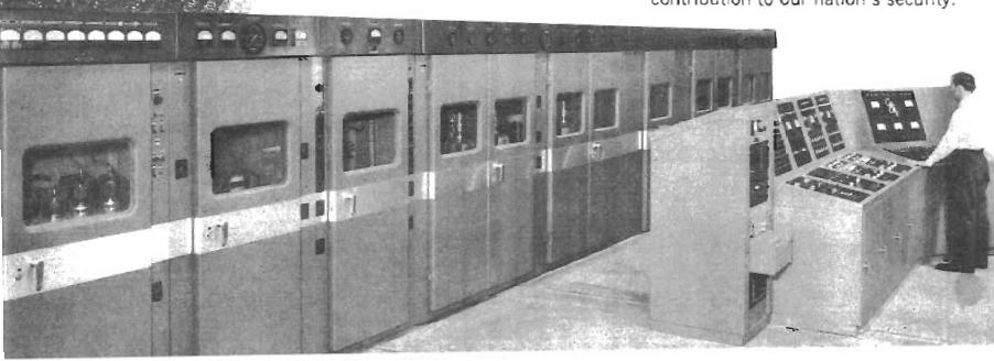
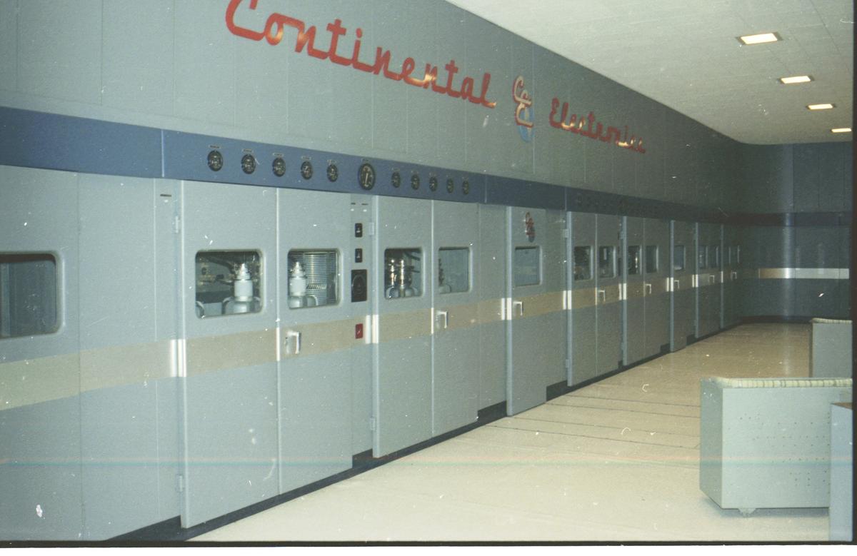
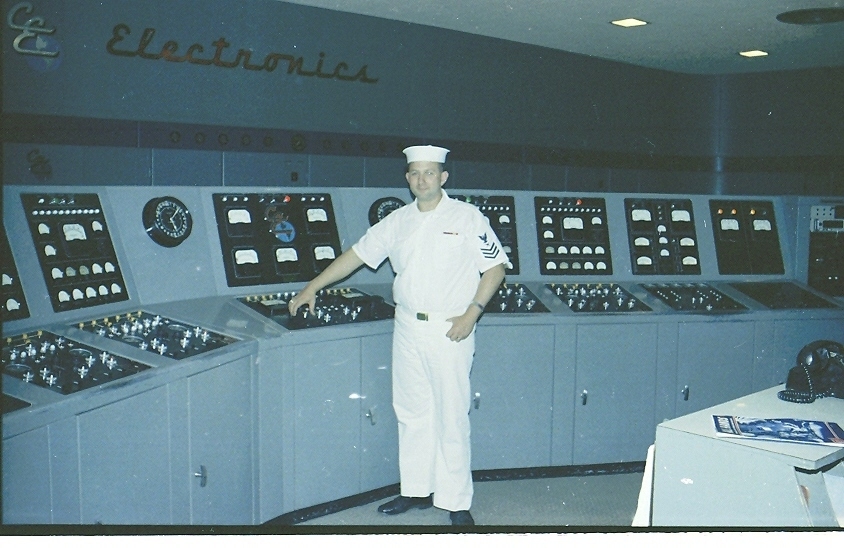
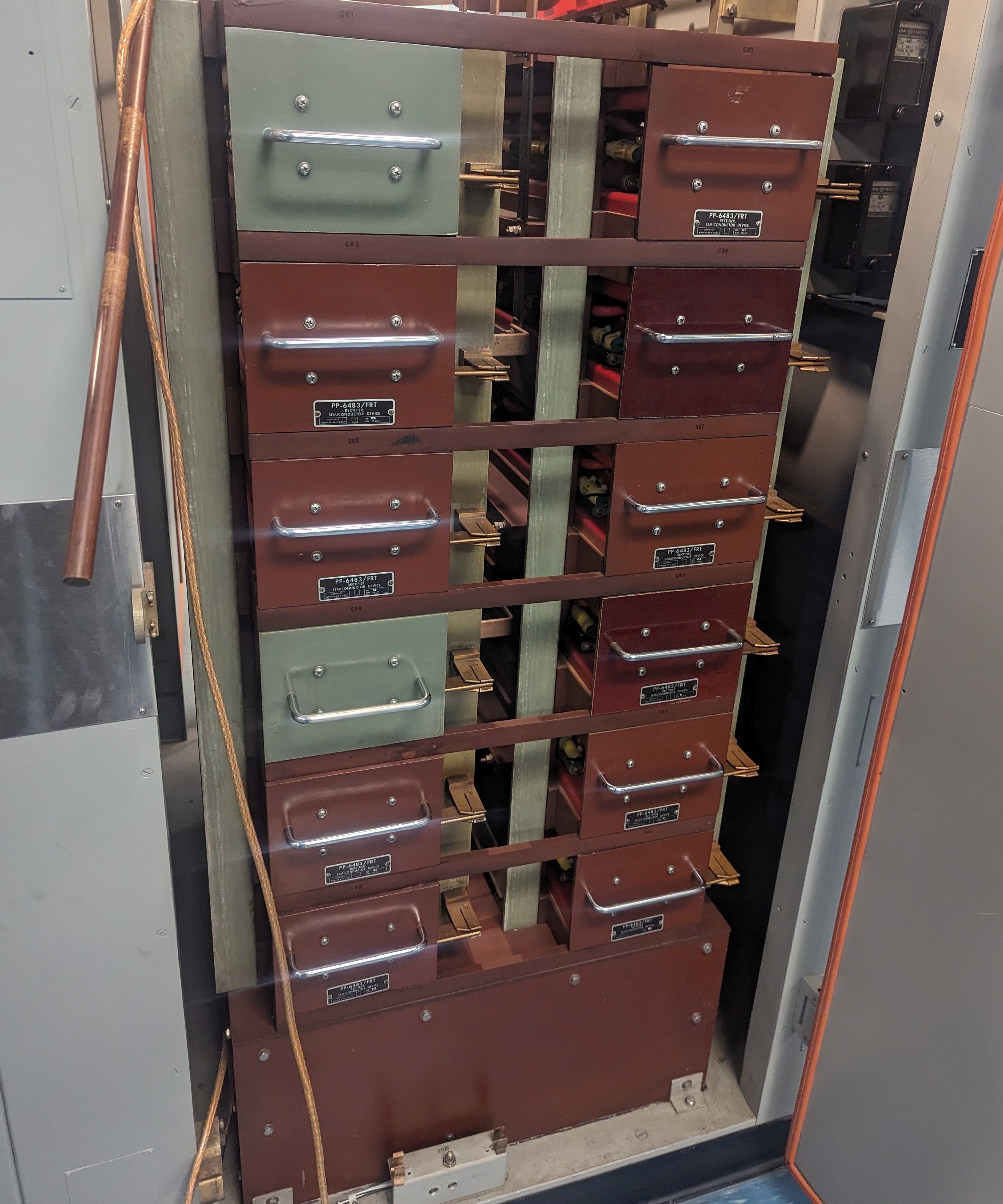
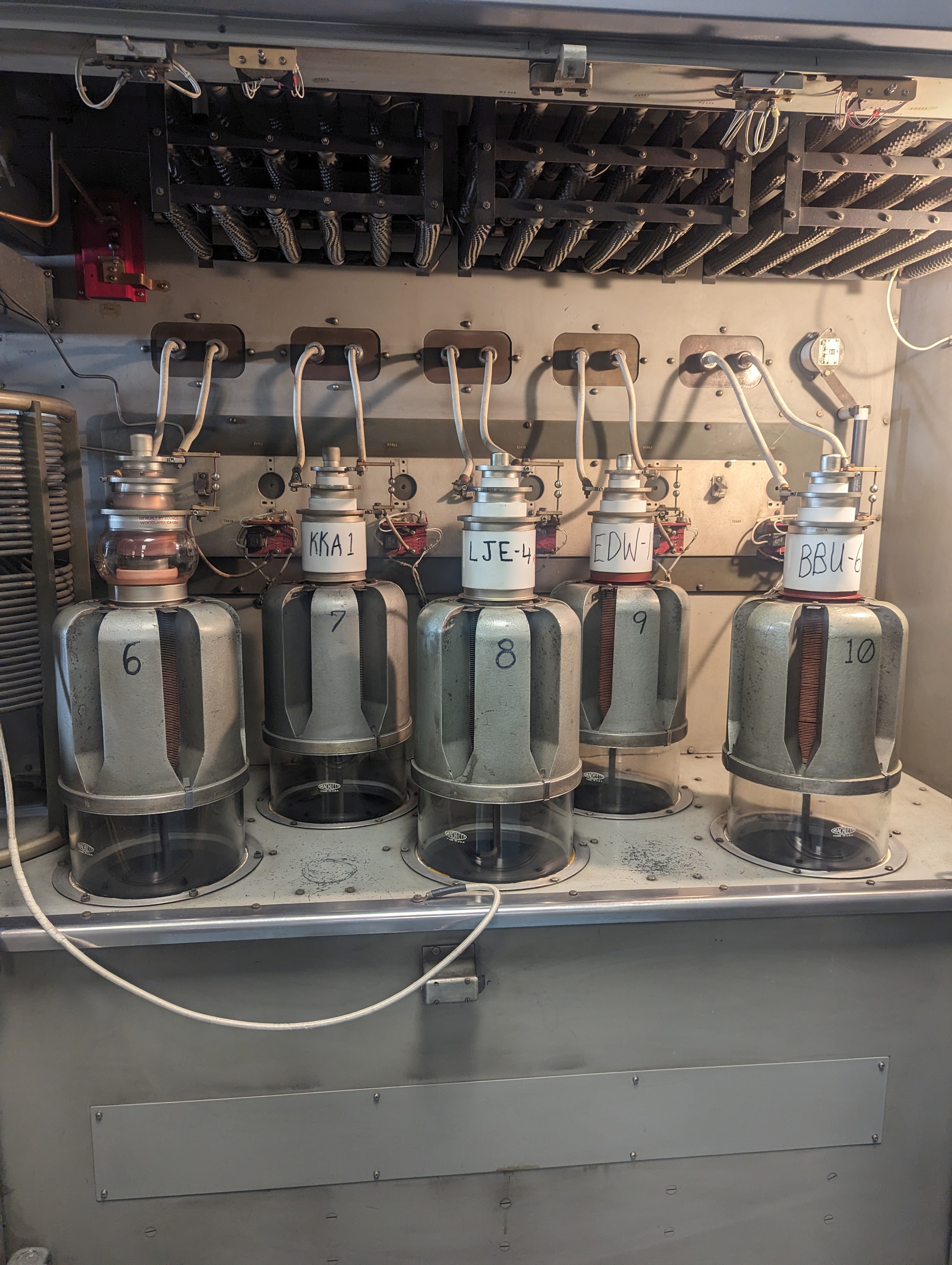
2,000,000 watt AN/FRT-31 Transmitter
|

Component Index to be added |

|
In 2000, the AN/FRT-31, -64 and -67 were upgraded with digital sine wave synthesis solid-state IPA for the tube final PAs
|
Photos and text from October 1961 QST magazine article "NAA-1961"
- thanks to ARRL
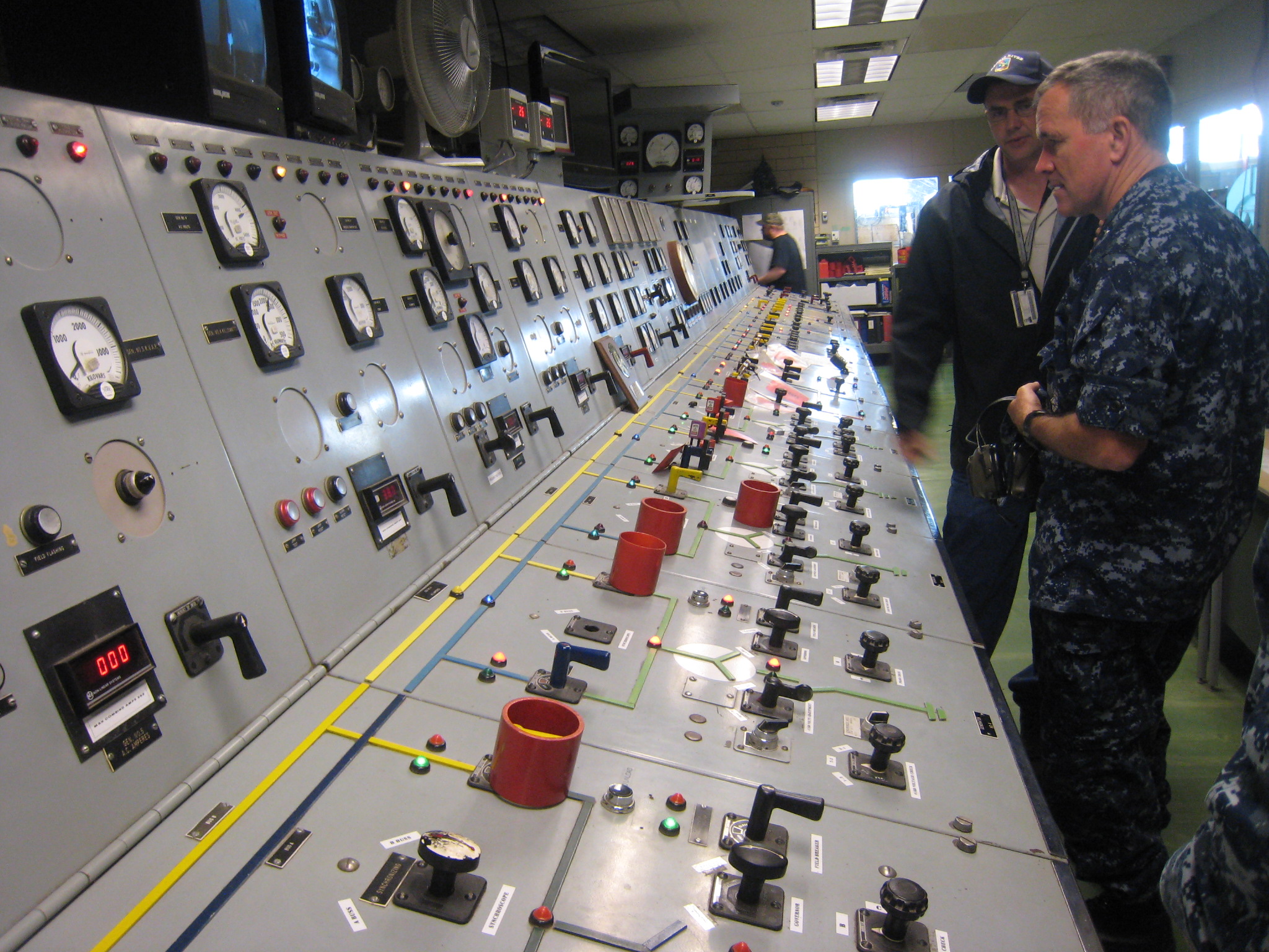
Photos and comments from Bob Mhoon, former station maintenance chief:
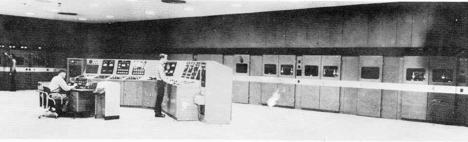
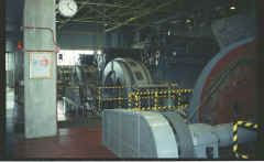
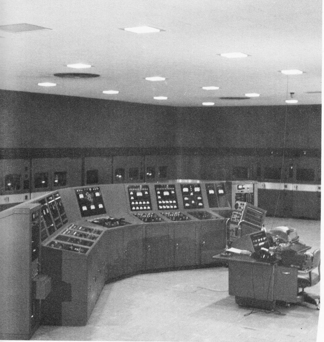
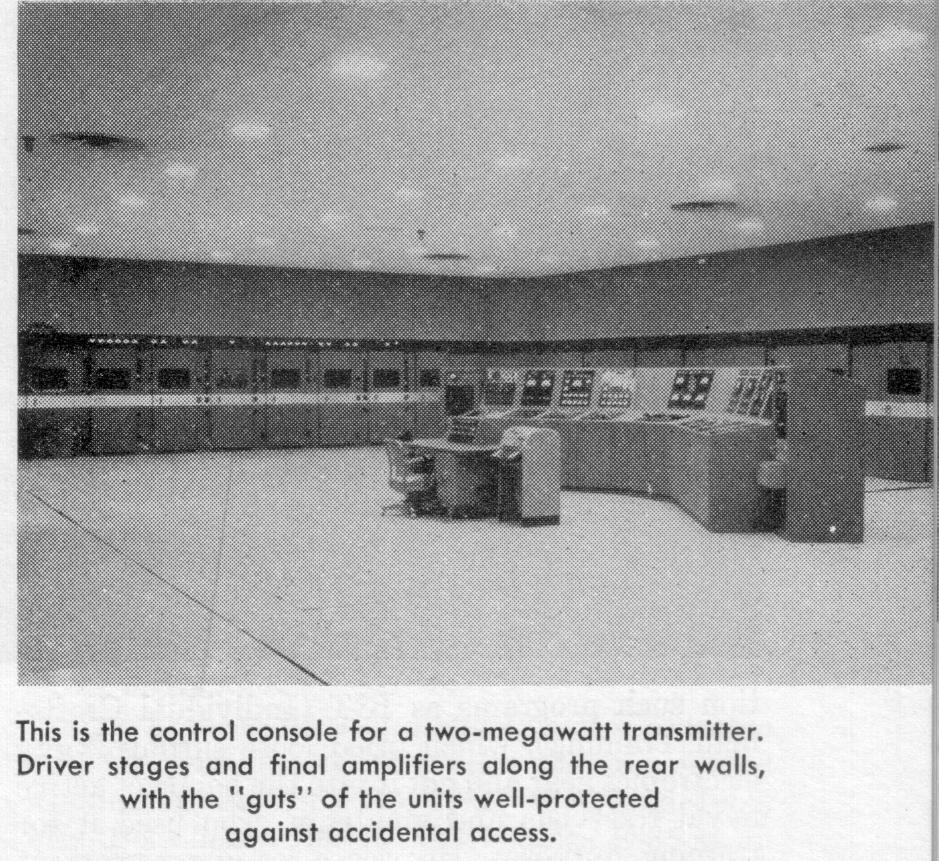
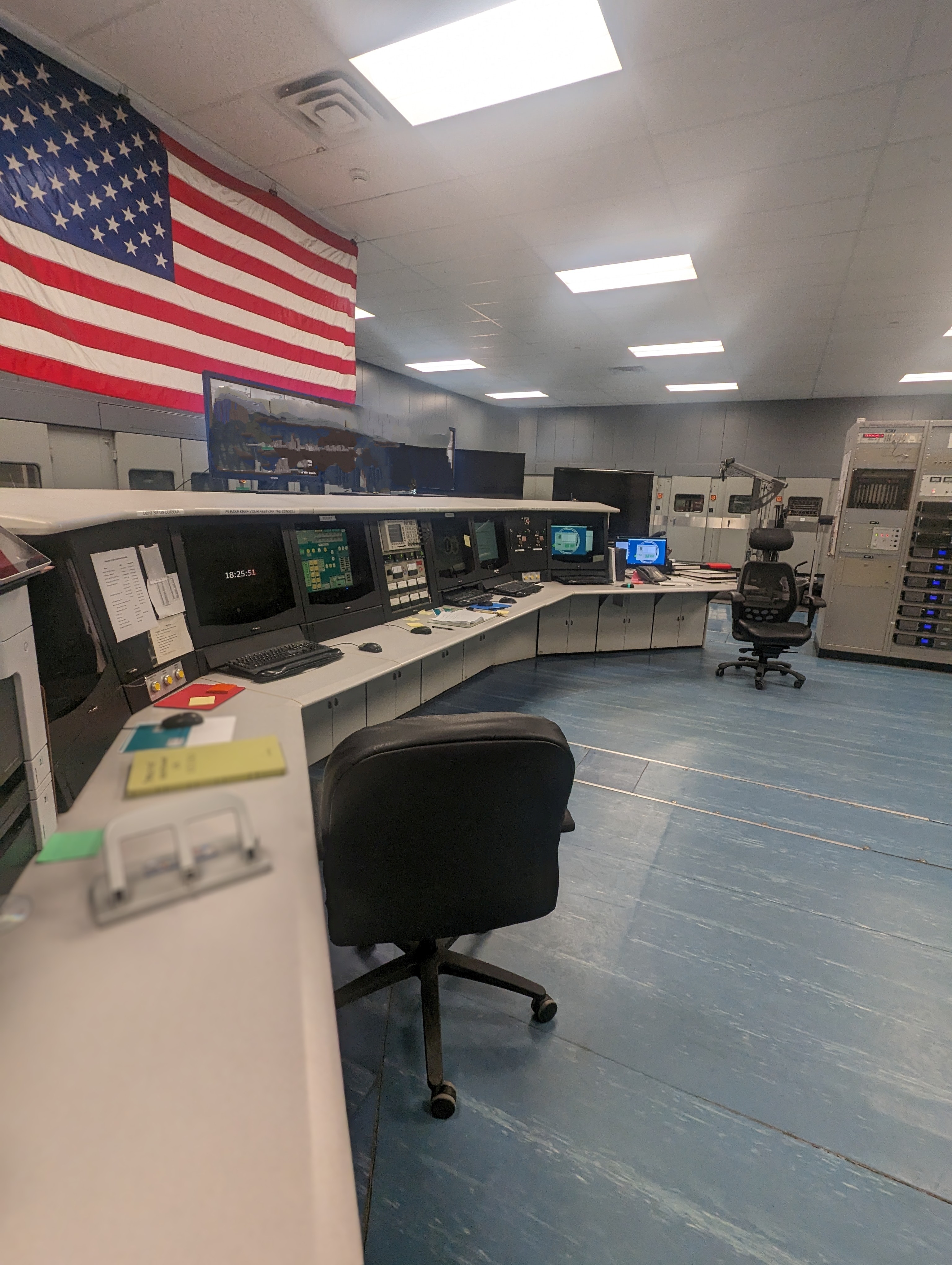
Nick, that 1961 photo of the Transmitter Deck, console and amps, is just how it
looked in 1981. There is a new digital console now, but I've not seen any
photos. Also, the area behind the amplifier cabinets was filled with the cooling
system. There were giant fans, probably 12 to 15 feet in diameter and they drew
air from outside the building through a filtering system. No problem with
cooling in winter.
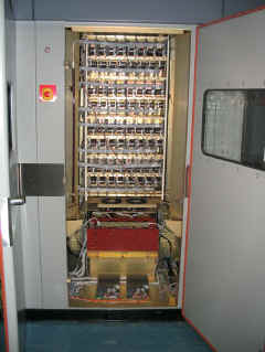
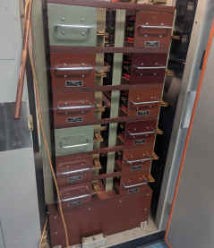
The system was powered via some very large HV AC breakers that were operated
with a DC control voltage from banks of what looked like small motorcycle
batteries. The battery sys was made by a French company as I remember. In 1979,
after 18 years of operation, they petered out and we were in a pickle. There
were no spares and the company was out of business. The fix was to hit town
(fishing villages) and buy up every battery available and most of the battery
cables. They were placed on freight carts (flat wagons) and wired in
series/parallel to match the original system. It took months to get motorcycle
batteries and custom design the cabinet. Because of gassing, we had to have a
hood and vent installed over the top of the banks.
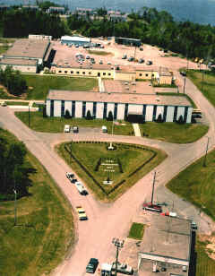
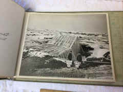
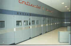
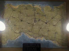
"Admin and housing area of the main base. The HF site was across the road and VLF was a couple of miles off to the left in
this photo."
Note: HF site transmitters were
AN/FRT-39's and AN/FRT-40's.
"We took delivery of diesel fuel via our own pier and had a 22K barrel storage facility. The oil was for base heating and running the power plant which had five giant diesel engines." |
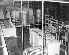
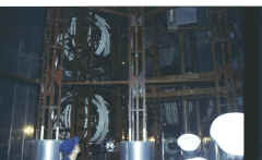
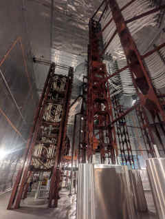
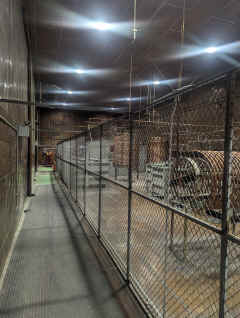
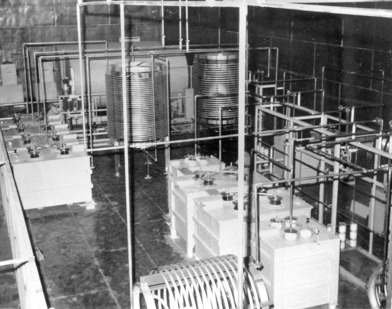
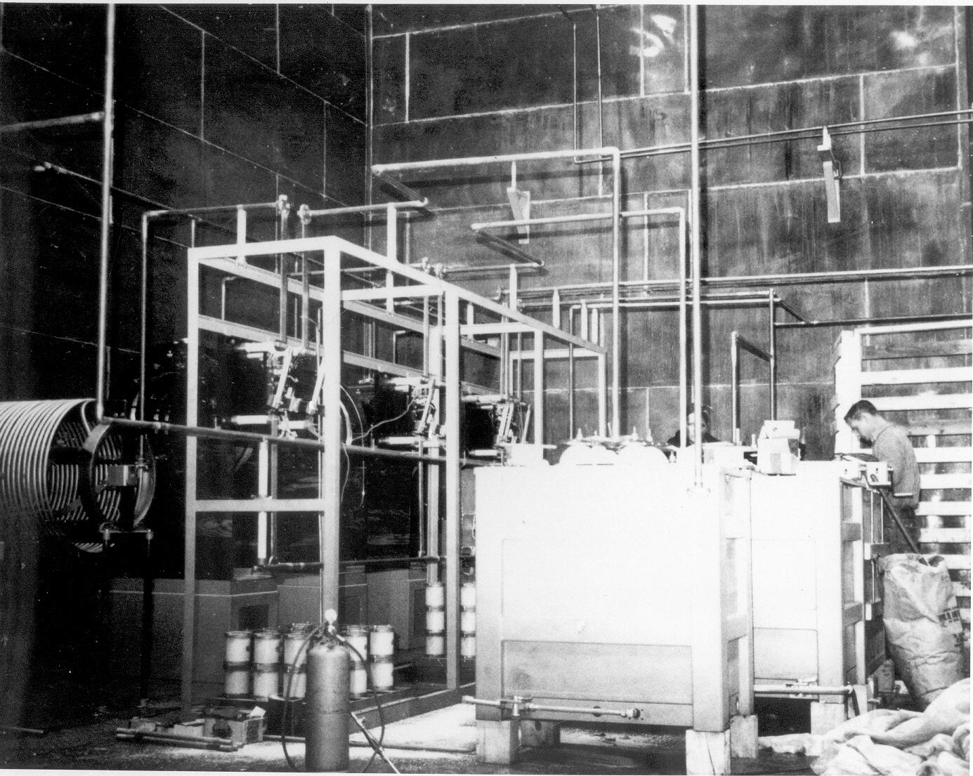
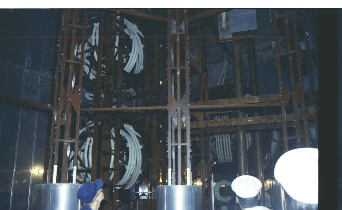
"The combiner room where the transmission line connected to the transmitter and ran to the helix
house. The box-like units are capacitors. The very left is the top of a chain link fence and note the room walls are covered in copper plate. When we took tour groups through we’d have people hold fluorescent bulbs that were on the fence (strictly for the show) and turn off the lights. Then they would be told to raise the bulbs overhead and they would light up the whole place from stray RF over the fence top."
|
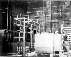
"Another photo of the combiner room. Note the bank of white capacitors. They actually bolt together via flanges and each one weighed
about ten pounds." |

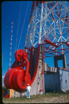
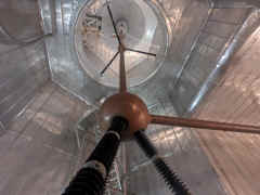
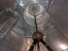
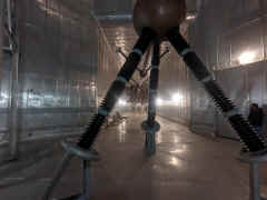
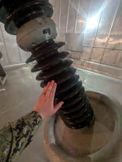
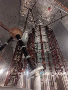
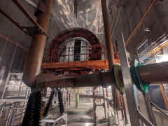
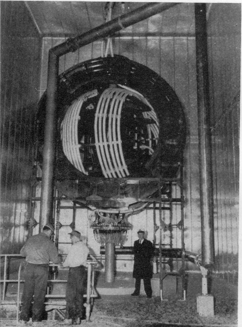
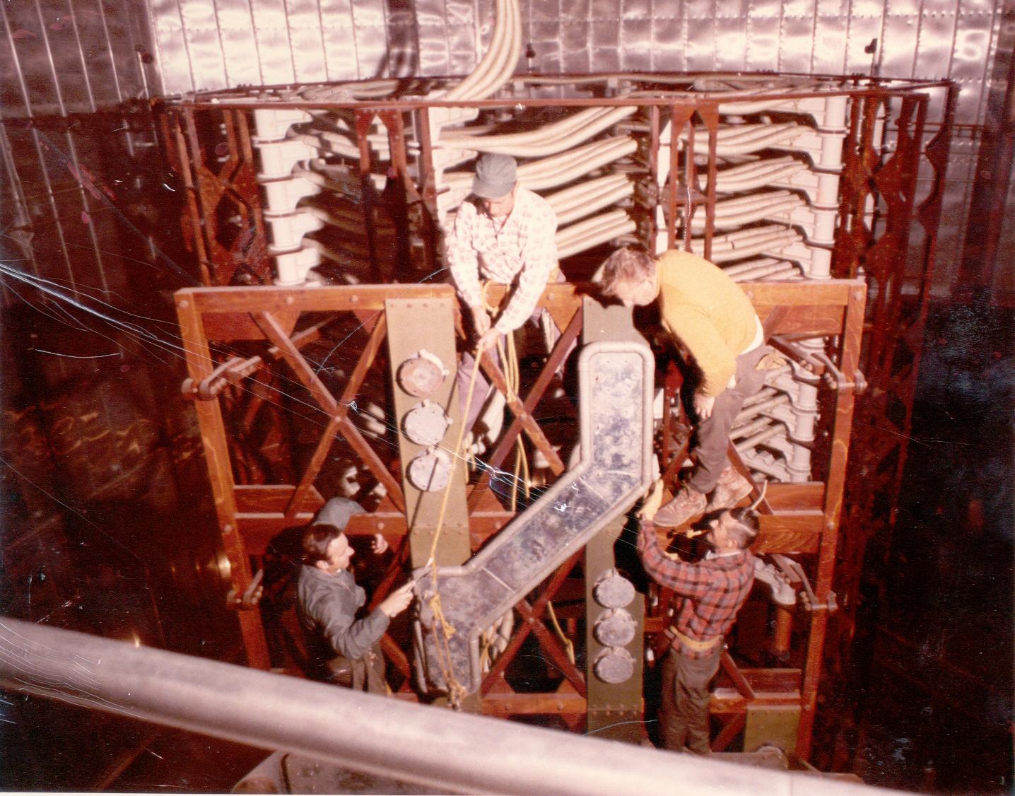
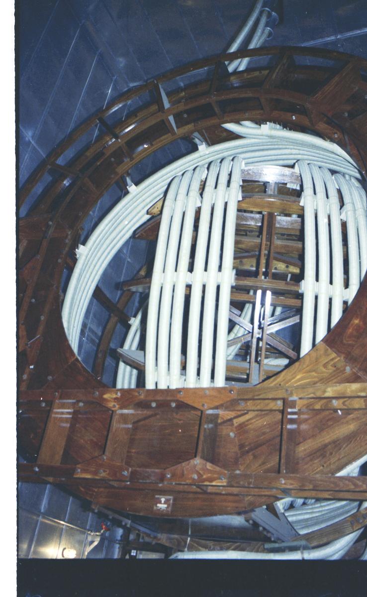
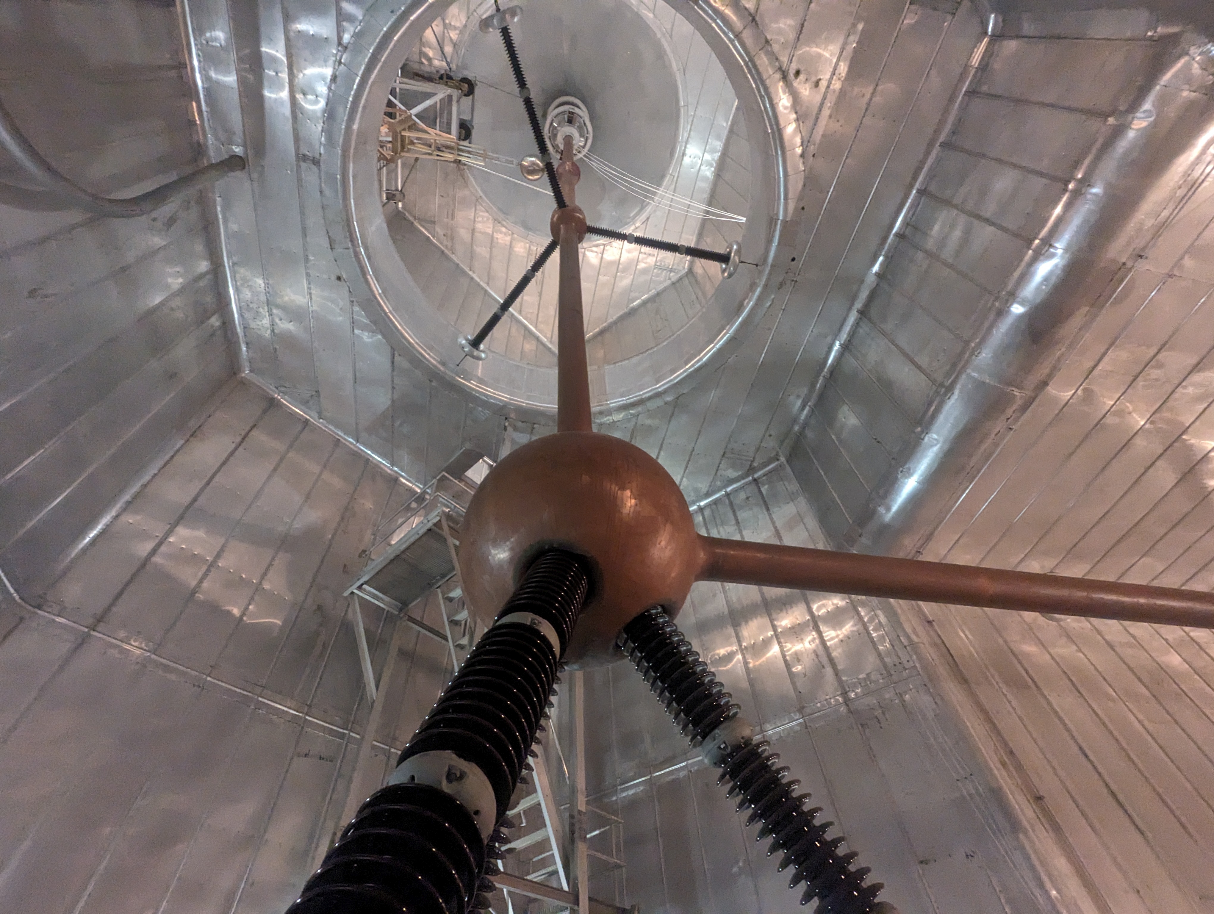
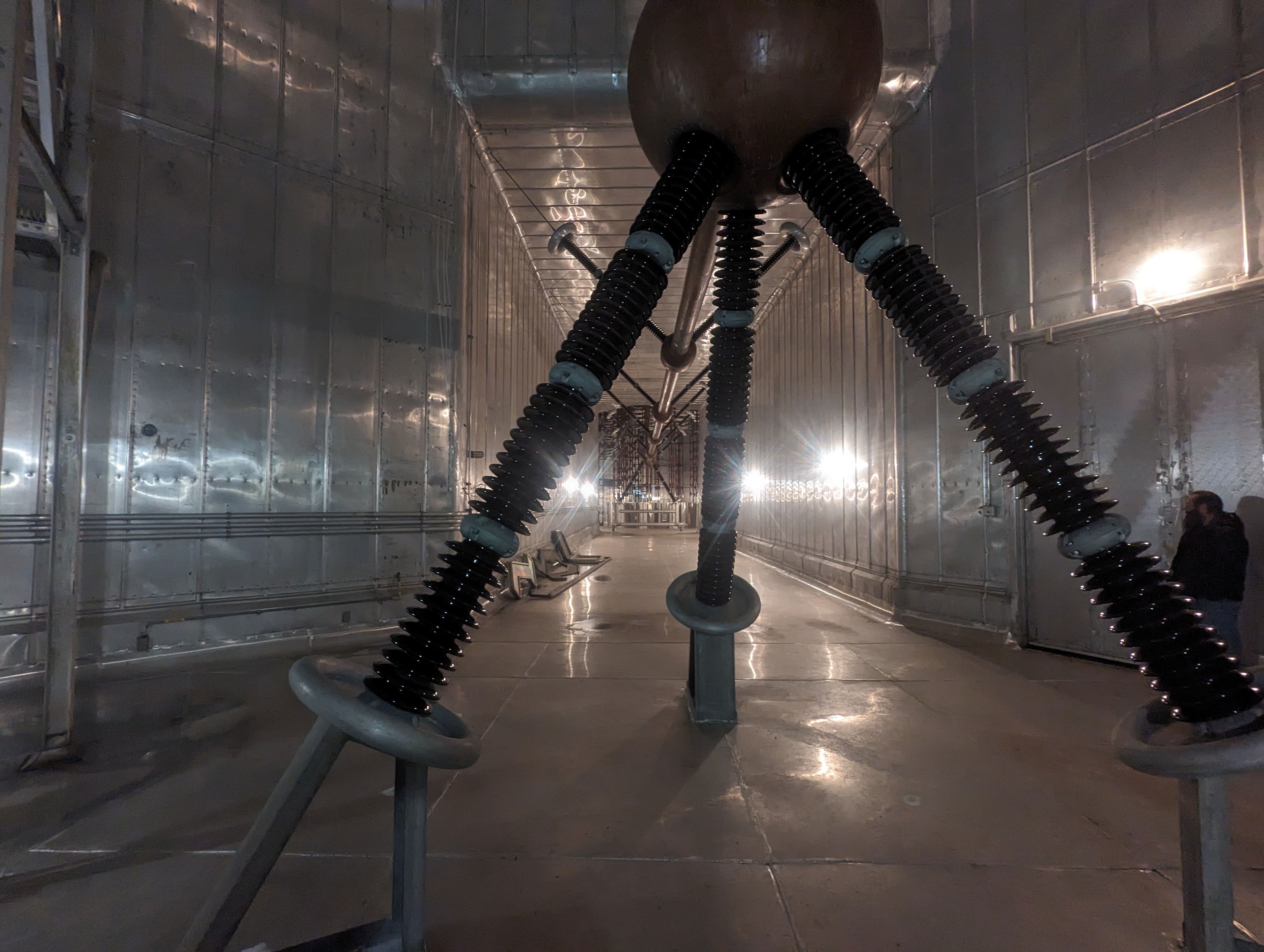
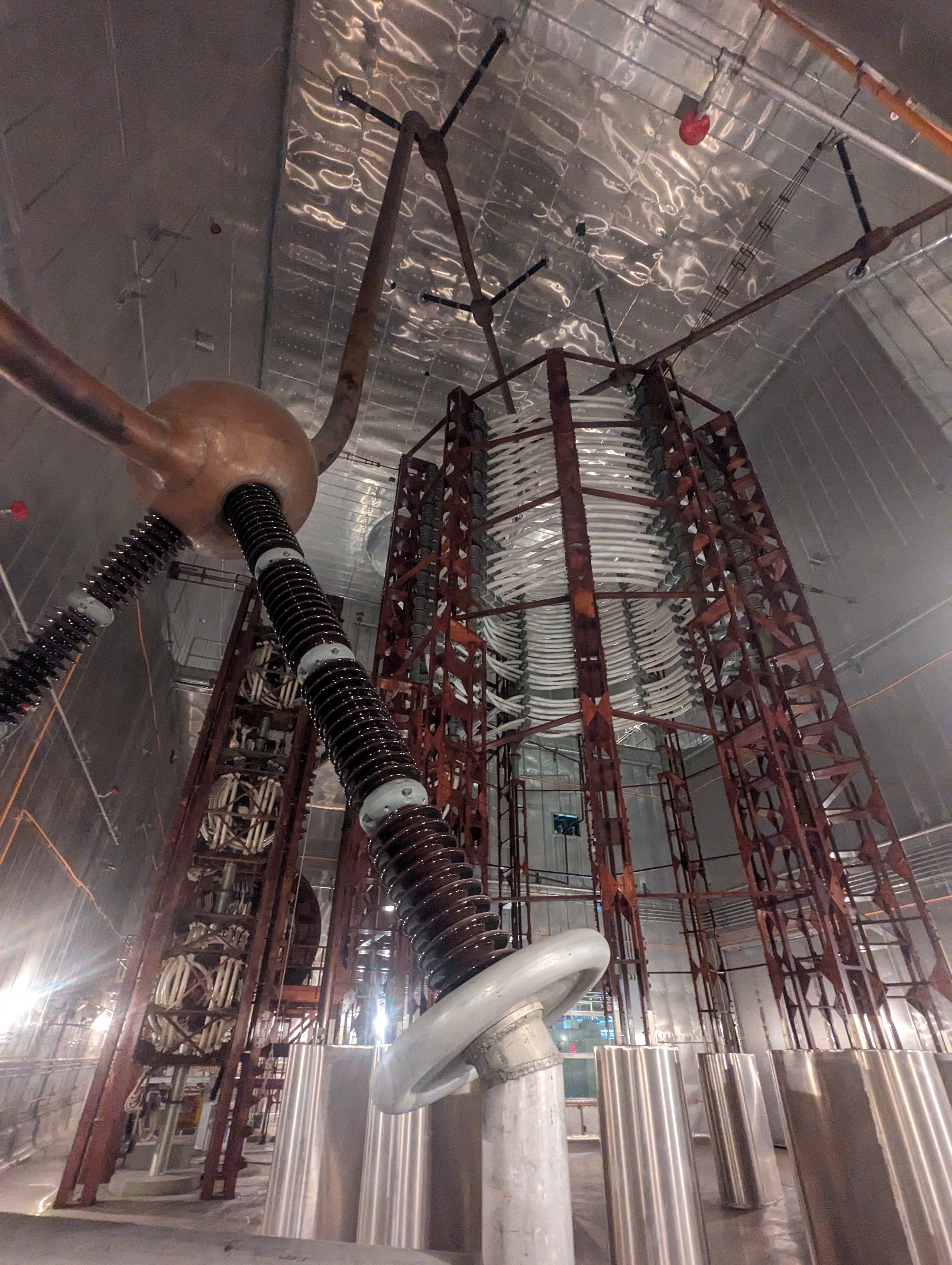
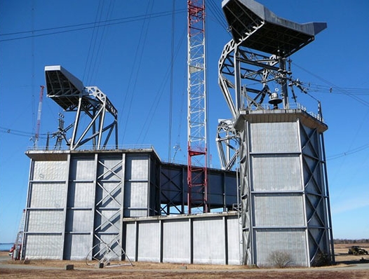
"The tap for tuning the frequency of the system. That is a giant tuning coil inside of a four story building called a helix house. There is a massive insulator on top of the helix house that looks like a spark plug. It was sealed and filled with an inert gas. Generally these failed in the winter and were hell to change. The helix was the center of each array." |
|
|
 |
 |
 |
 |
 |
 |
 |
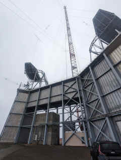
AN/FRT-40 HF Transmitters
 |
2024 Photos
|
 |
 |
 |
 |
 |
 |
 |
 |
 |
 |
 |
 |
 |
ML-6697A
air-cooled tubes
 |
 |
== |
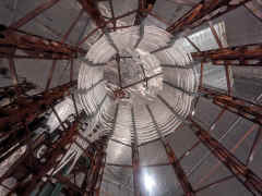
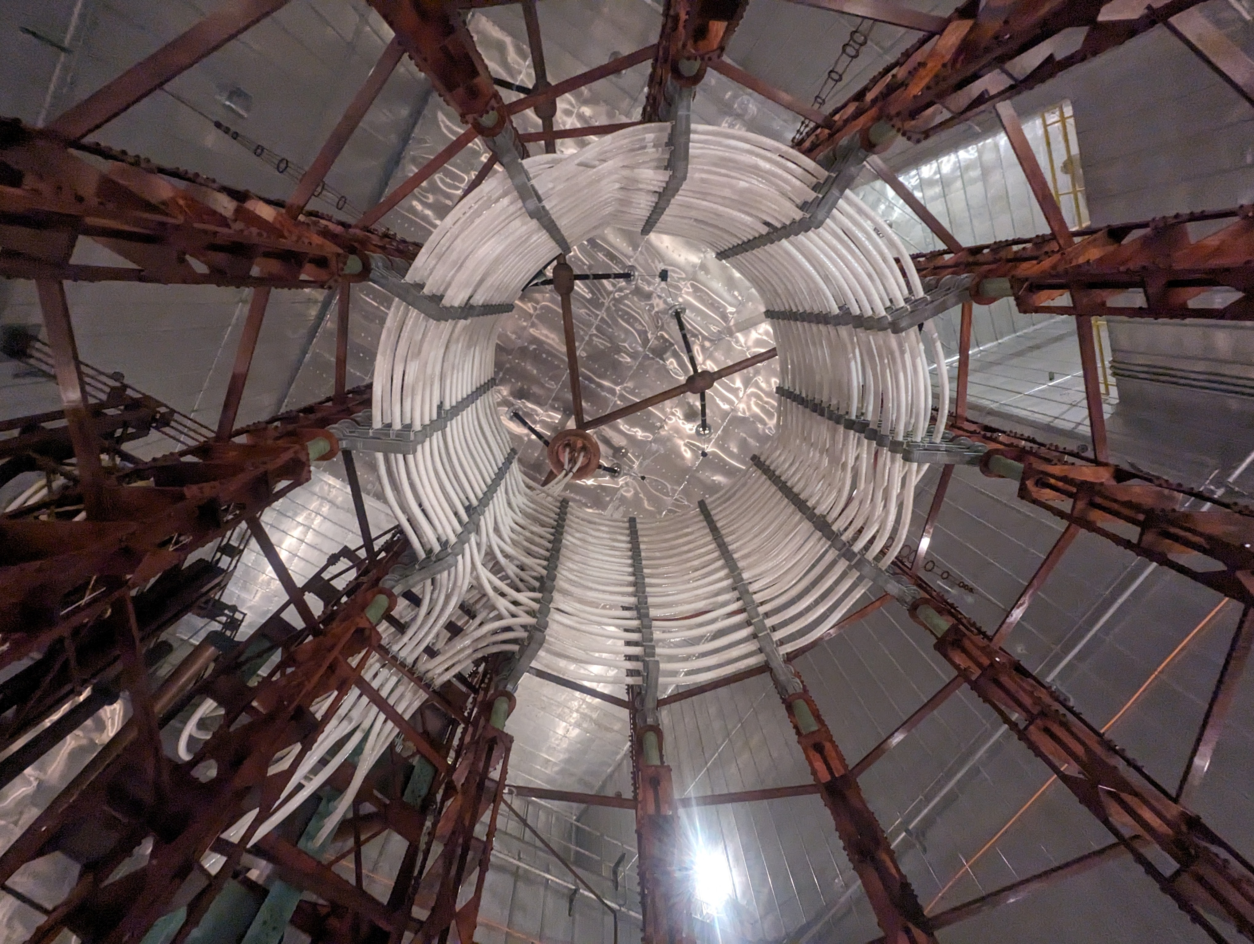
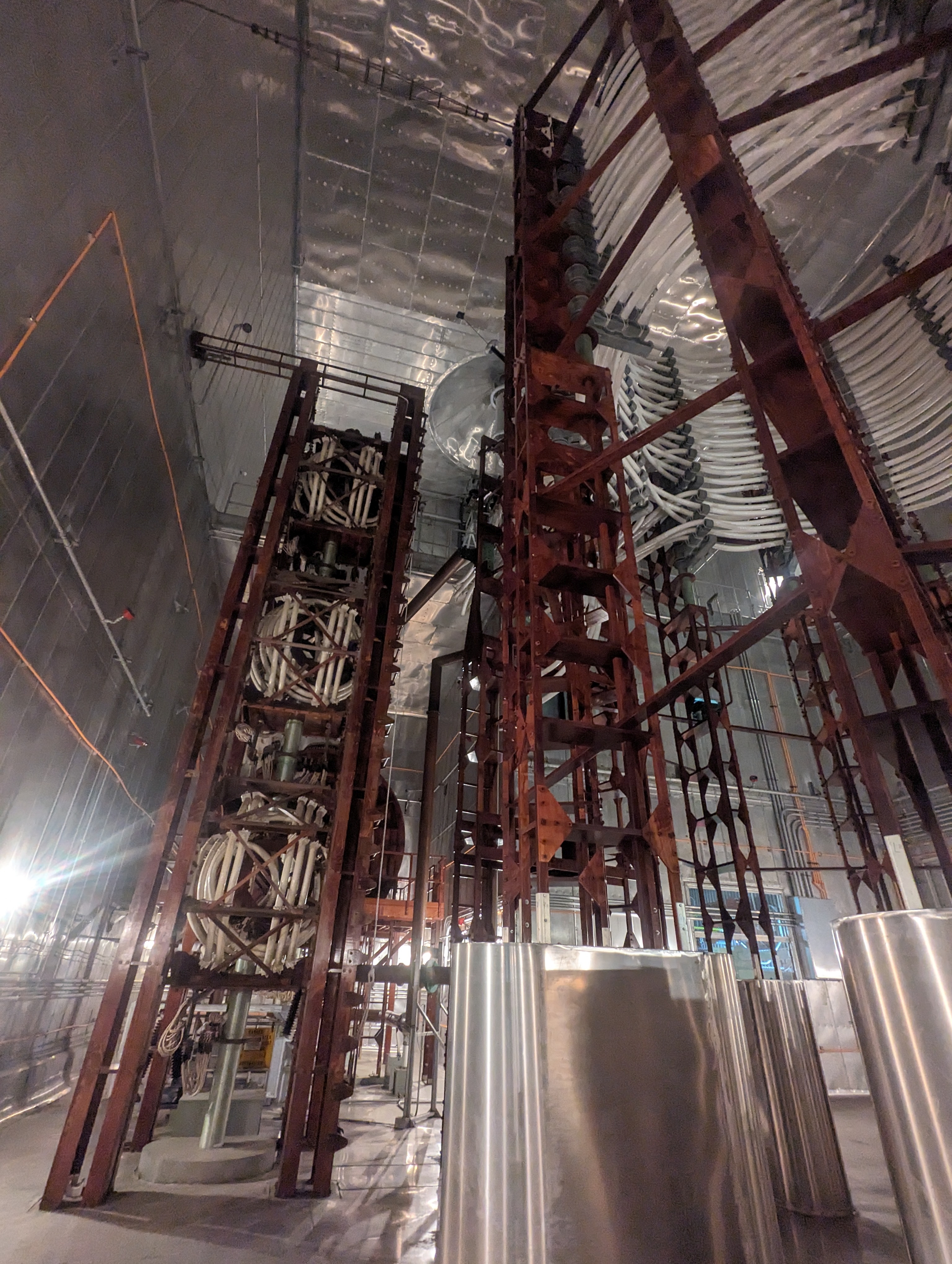
The antenna is tuned and matched by a set of high-Q, air-wound
inductors and variometers located in the helix house. The primary tuning is done
by a huge air-core inductor known as the helix. The windings of the helix are
made with three pieces of 4-inch diameter Litz wire in parallel. The top of the
helix is connected to each of the three feed-through bushings. The connection to
the bushing on the main part of the helix house is made directly using two
pieces of the 4-inch litz wire in parallel.
The connection to the bushings on the end of the two galleries
is made using a large (8-inch diameter) copper bus. The helix has several taps
that can be changed manually to provide coarse changes to the antenna tuning
circuit. It is usually only necessary to change taps when changing frequency.
Variable tuning to compensate for environmental changes is performed by a large
air-core variometer, which is also wound with three pieces of 4-inch Litz wire
in parallel. This tuning variometer is in series with the helix inductor in the
antenna circuit.
In each helix house there is a large ferrite core inductor known
as a saturable core reactor. The inductance of this reactor can be rapidly
varied electronically over a finite range of values. The reactor can be
connected in parallel with a portion of the helix and/or the tuning variometer.
It is used to tune the antenna in synchronism with the two frequencies of the
minimum shift keying (MSK) modulation. The MSK waveform consists of two
frequencies selected to transmit marks and spaces. The reactor driver receives
an antenna tune signal from the modulator, which enables it to tune the antenna
synchronously with the mark and space frequencies. The saturable core reactor
provides a method of increasing the effective bandwidth of the antenna
(bandwidth enhancement). When the reactor is operating, it resonates the antenna
circuit at both the mark and space frequency, and the impedance reflected to the
transmitter is nearly pure resistance.
This reduces the stresses on the transmitter, transmission line,
and matching components. These stresses are greater for larger values of Q, which
occur at lower frequencies for Cutler. In fact, the reactor is necessary to
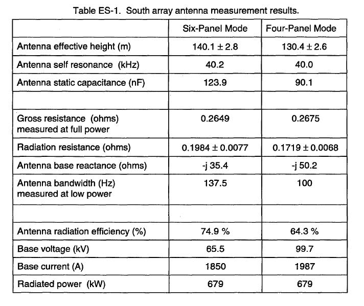
radiate full power at the lower frequencies at Cutler. For six-panel operation
on 24.0 kHz, the reactor is not necessary to radiate full power. However, for
four-panel operation, the antenna bandwidth is reduced and the reactor is
needed. The voltage on the reactor depends upon its helix tap connections. In
four-panel operation, the helix taps must be changed to keep from exceeding the
reactor voltage limits.
A coupling variometer converts the series resonant antenna to a
parallel resonant impedance and to change the impedance at mark and space
frequencies to match the transmission line impedance of 100 ohms. This coupling
variometer, known as the triple deck, consists of three single variometers in
parallel, each wound with 4-inch diameter Litz wire. The coupling variometer is
connected from the tuning variometer to ground. The 100-ohm transmission line
from the transmitter building is also connected to the top of the coupling
variometer.
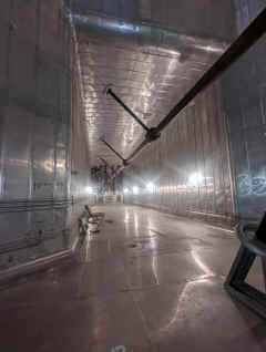
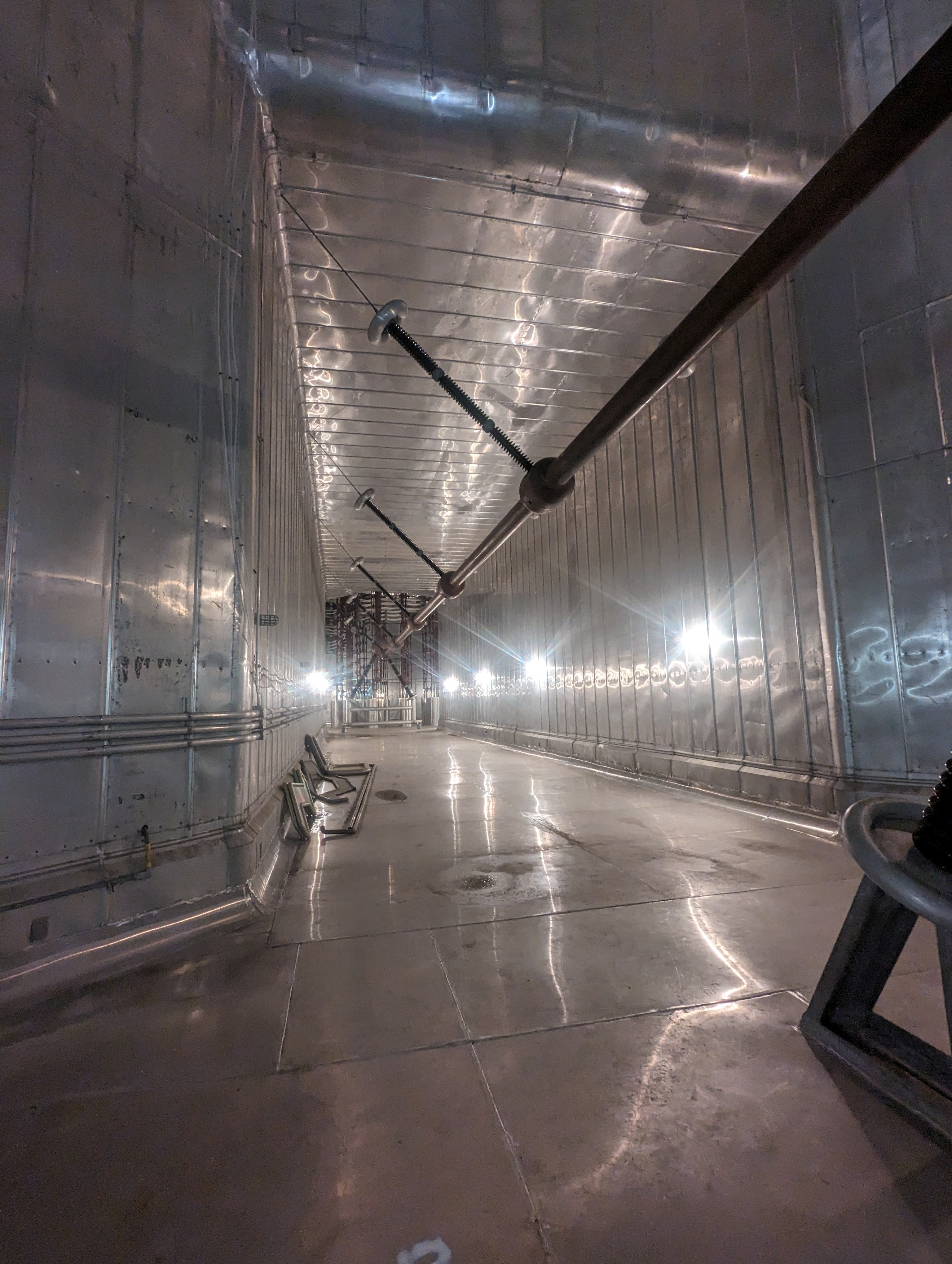
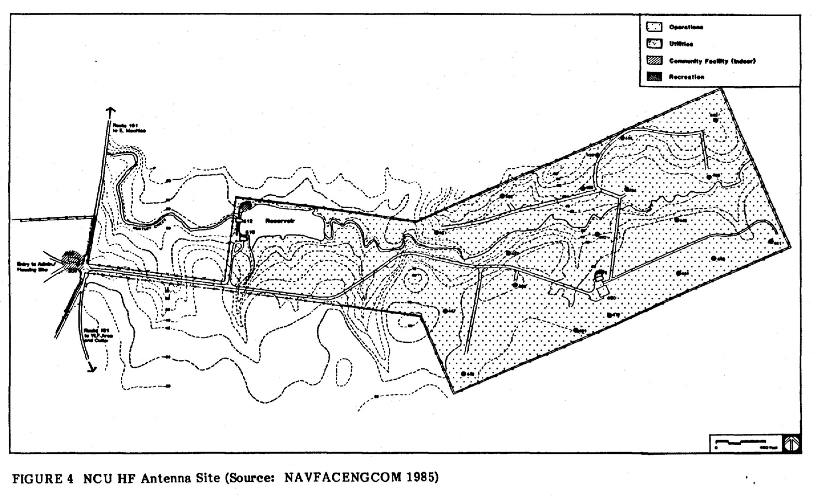
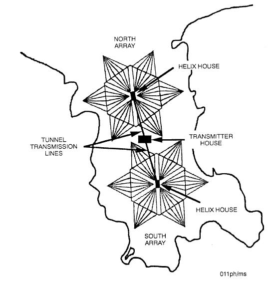
The transmitter is located in a building approximately halfway
between the center of each array (figure 1). The transmission line and other
cables for power, monitoring, and control are routed to each helix house through
a tunnel large enough to walk through.
Antenna Arrays
The Cutler VLF transmitter. located in Washington County, ME, became operational on 4 January 1961. The Cutler antenna consists of two arrays. each having six diamond-shaped topload panels made up of cables hoisted by halyards that are attached to 13 towers. Each panel has eight active cables. called conductors. that carry the radio frequency (RF) current. One support catenary cable crosses the eight conductors in the center of the diamond. The RF conductors in these topload panels are specially designed with low enough resistance to have acceptable losses for VLF radiation. but enough resistance to enable deicing with 60-Hz current during winter months. Most of the cables consist of a 1-inch-diameter strand of a special alloy called Calsun bronze. However in order to provide corona-free operation at the high-radiated power levels, some sections of the conductors are 1.5 inches in diameter. The 1.5-inch diameter conductors were specially made with hollow center conductors covered by Everdure alloy exterior wires in order to meet the size. Strength. resistance. and weight requirements for use in the antenna. These cables. known as hollow core cables. make up part of the outer two cables on each panel. The hollow core sections on the cables inside of the catenary are 225 ft long, while those on the outside of the catenary are 775 ft long.
ANTENNA DESCRIPTION
The US Navy VLF transmitting station at Cutler, ME is the "flagship" of the Navy's fixed very low frequency (FVLF) transmitting sites and has been operational since 4 January 1961. The station is located in Washington County, ME on a peninsula near the small town of Cutler.
This site normally operates with a radiated power level of 1-million watts, termed "full
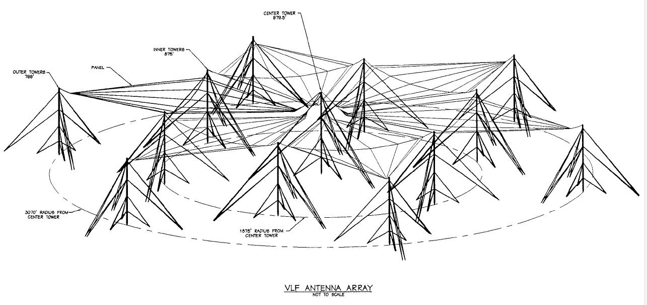
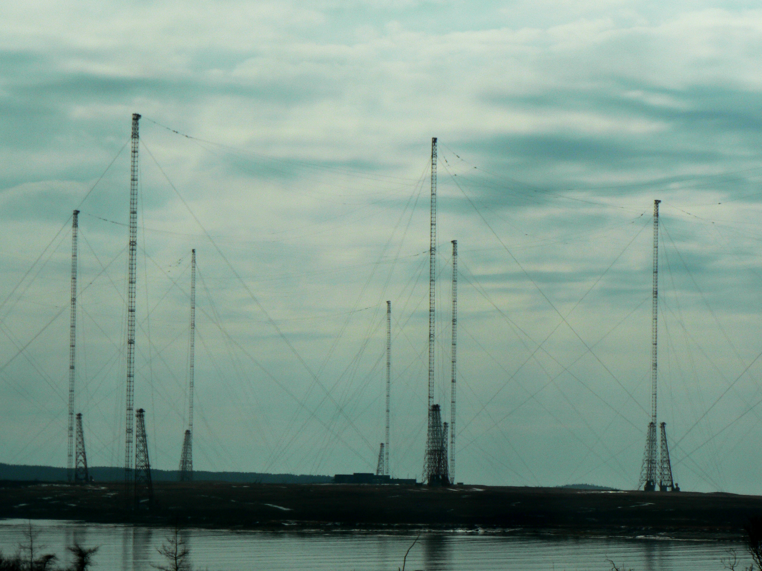
power", and at times as high as 1.8-million watts radiated, termed "maximum power. In order to radiate power levels of this magnitude in the VLF band. an enormous antenna system is required. The Cutler VLF antenna consists of two separate arrays (north and south), each consisting of 13 towers. Every array has a center or zero tower called
N0 (for the north array) and S0 (for the south array). which are 997.5 ft tall. Each array has six middle towers
575.0 ft tall. which are located with equal spacing on a circle of radius 1825 ft centered on the zero tower. Each array also has six outer towers 799.0 ft tall. also equally spaced on a circle of radius 3070 ft centered on the zero tower. A plan view of this antenna is given in
figure 1. Every array is over 1 mile across and together they cover almost the entire peninsula. This antenna system is one of the largest in the world.
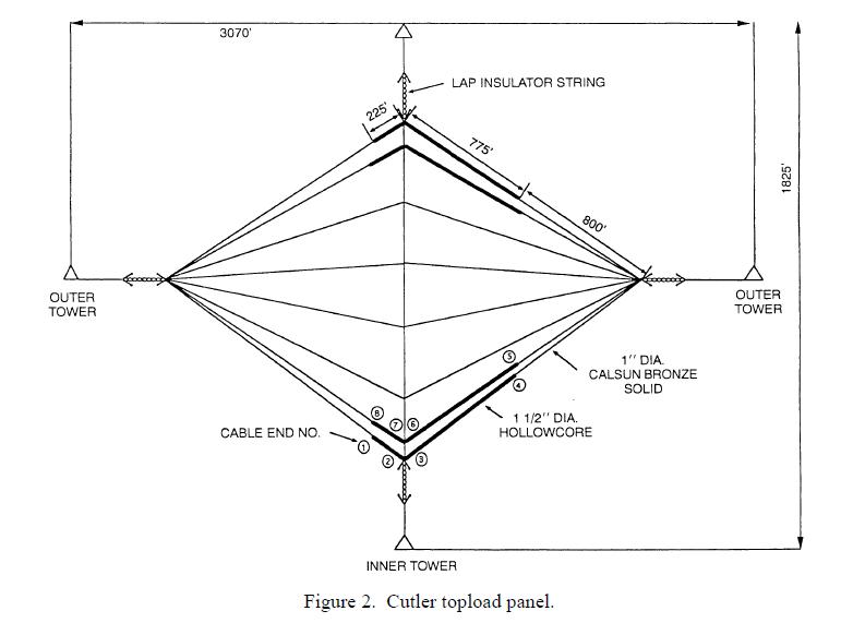
Each array consists of six diamond-shaped panels made up of cables supported from the towers by insulated halyards leading to permanent winches located at the bottom of each tower. A top view of one panel is given in figure 2. Each panel has eight active cables called conductors that carry the RF current. One support catenary cable crosses the eight conductors in the center of the diamond. The RF cables in these topload panels are specially designed to have low enough resistance to have acceptable loss for VLF radiation, but enough resistance to enable deicing by running 60-Hz current through them when needed during the winter.
Most of the conductor cables consist of 1-inch-diameter wire made from a special alloy called Calsun bronze. However, in order to provide corona-free operation at the high-power levels, some sections of the cables are 1.5 inches in diameter. These cables, specially made with hollow center conductors covered by exterior wires, were made of Everdure alloy in order to meet the size, strength, resistance, and weight requirements. The cables, known as hollow core cables, make up part of the outer two cables on each panel. The hollow core sections on the cables inside of the catenary are 225 ft long, while those on the outside of the catenary are 775 ft long.
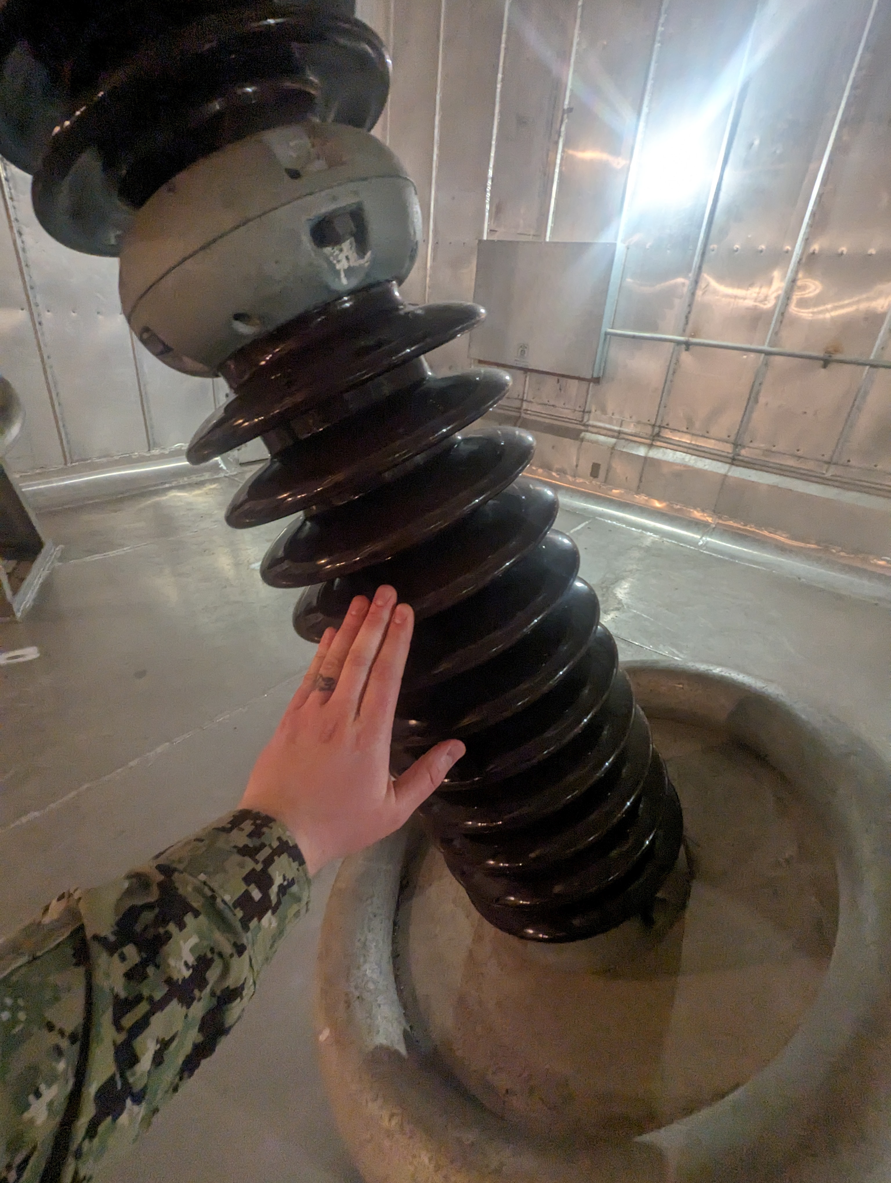
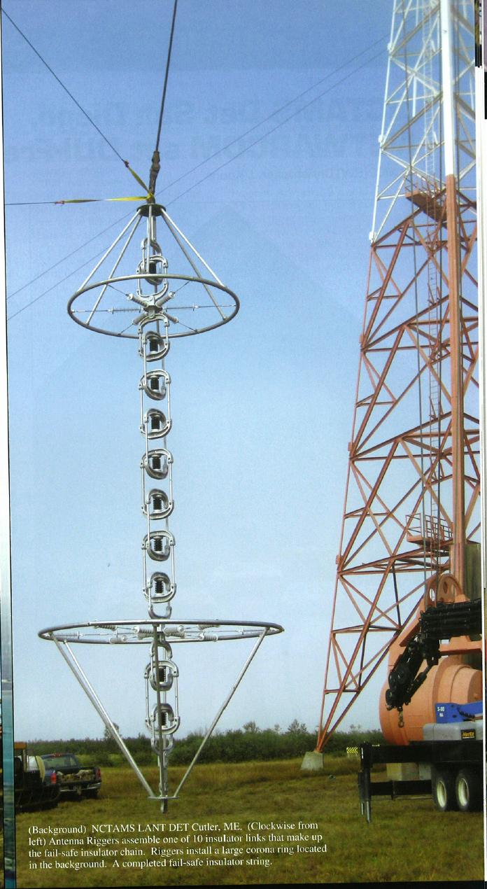
The halyards are insulated from the panels by a string of 16 Lapp compression cone fail-safe insulators with large grading rings on each end (figure 2). Each individual fail-safe insulator weighs 750
lbs and the complete insulator string, plus hardware, weighs more than 6 tons. One insulator string is on each panel
corner and the total weight of insulators on each panel exceeds 24 tons.
DEICING
The weather conditions along the coast of Maine are such that severe icing occurs during the winter months. The original requirement for the VLF Cutler transmitter called for continuous operation in all weather conditions. In order to survive severe icing, the antenna halyards are led through a counterweight system so that as the ice buildup increases the panel weight the counterweights let the halyards out, lowering the panel. The counterweight system is designed to allow the panels to lower all the way to the ground, if necessary. During installation, this actually happened. As the ice melts the counterweights hoist the panels back to their original position: thus, the arrays will survive no matter how large the amount of ice buildup.
However, as the ice builds up and the panel lowers, the antenna capacitance increases and the antenna must be retuned. The tuning range is limited and the limit eventually reached whereby the antenna can no longer be tuned and transmission ceases. The solution to this problem is to de-ice the antenna system by heating the wires with 60-Hz current. Constructing a deicing system that would allow simultaneous transmission and deicing would have been prohibitively expensive. Instead, two arrays have been built that allow transmission on one array while the other is deicing. This approach allows ice to build up on the transmitting array while the other array is deicing. When the one array is sufficiently deiced, the roles are reversed. This continues as long as necessary. Obviously, for this approach to allow continuous transmission, the deicing system must completely remove ice from one array in, at most, the amount of time it takes to reach the tuning limit on the other array The design value for heating chosen to accomplish this was 1.64 Watts per square inch of surface area, which corresponds to approximately 500 kW per panel or 3 MW for the entire array. The Cutler deicing system has the capability of operating at up to four times this much heating. Note that deicing power significantly exceeds transmit power.
The topload panels are fed by a four-wire cage made up of 1-inch copper cables. For transmitting, eight topload panel cables are all fed in parallel, one pair fed by each of the cage wires. For deicing. the topload cable pairs are fed in series with 60-Hz current. To provide the correct amount of heating with reasonable 60-Hz current, the topload cables need to have an appropriate resistance. For a given current, the heating in watts per square inch should be essentially the same for all cables. The deicing system is configured such that each 1-inch-diameter copper cable in the feed cage carries the full deicing current. This current is divided between two of the 1-inch-diameter topload conductors. Since heating is proportional to current squared, these topload cables must have about four times the resistance of the feed cage cables to provide the same heating This was accomplished by making the 1-inch topload cables out of Calsun bronze, which has a conductivity equal to 19% of copper.
The heating in the 1.5-inch-diameter portion of the cables must be 50% greater than in the 1-inch diameter cable because the surface area is proportional to the diameter. Consequentially, the larger diameter sections must have more resistance. which is contrary to the normal variation of resistance with diameter. This was accomplished by making a composite cable known as hollow core by using hollow copper tubes in the inner portion and wires of a copper alloy called Everdure which has a conductivity equal to 7.75% of copper for the outer portion. Mechanical connections of the topload conductor cables are made using swage-type end fittings combined with clevis shackles. Electrical connection is insured by crossing the mechanical connections with a 1-inch-diameter copper jumper cable clamped to the cables on both sides.


