AN/UGC-1(XN-1)
AN/UGC-1
(Teletype Corp.)

- thanks to Jim Haynes


AN/UGC-1A
(Trak Electronics Co.)

NAVSHIPS 94376(A) - 17MB pdf
AN/UGC-1(XN-1)
|
1956 Press Release Photo
|
|
|
AN/UGC-1
|
Manual NAVSHIPS
93408 - thanks to Jim Haynes
|
|
|
AN/UGC-1A
|
System Block Diagram
|
AN/UGC-1A manual NAVSHIPS 94376(A) - 17MB pdf
|
-- |
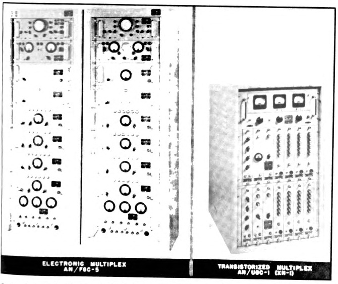 Comparison of the new high-speed telegraph transmitter-receiver with the equipment now in use. |
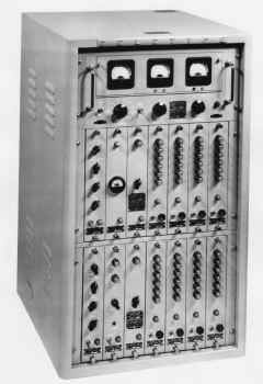
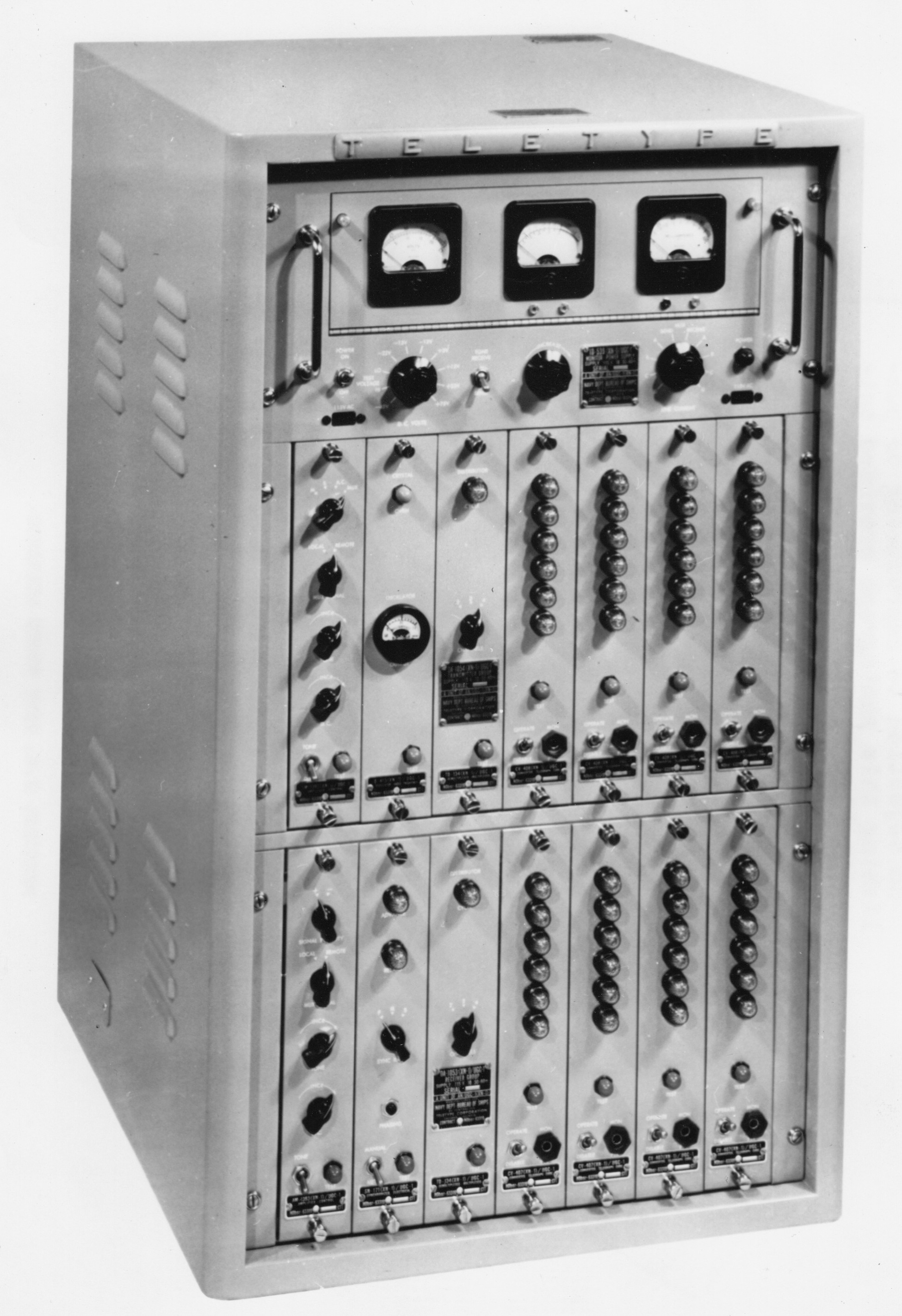
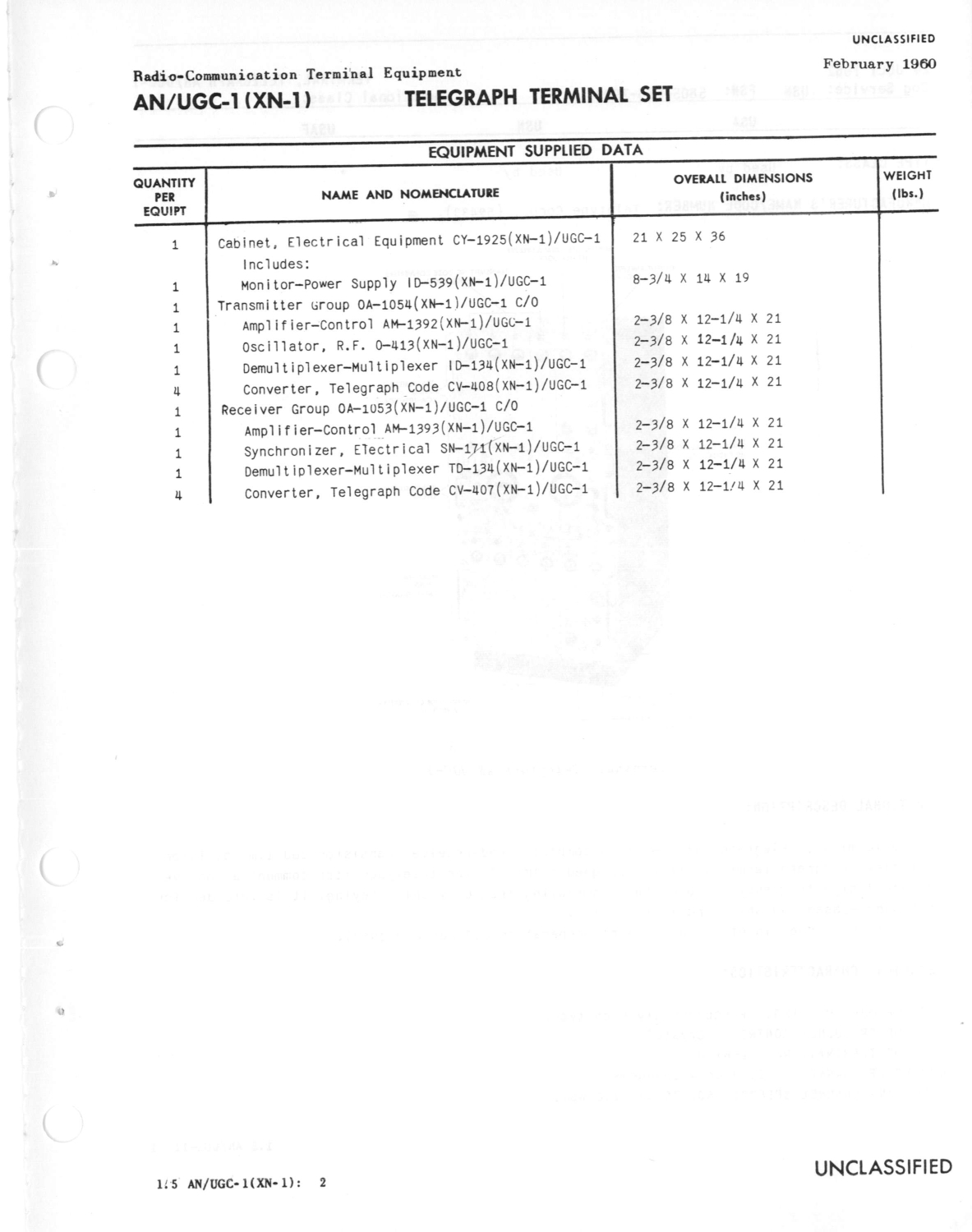
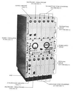
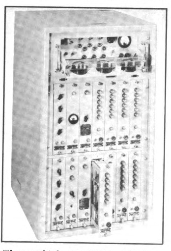 The new high-speed telegraph transmitter-receiver, with compartments open for servicing. AN/UGC-1 (XN-1) |
||
| Table 1 - Volume |
Electronic Multiplex AN/FGC-5 55 cu. ft. |
Transistorized Multiplex AN/UGC-1(XN-1) 10.9 cu. ft. |
-- |
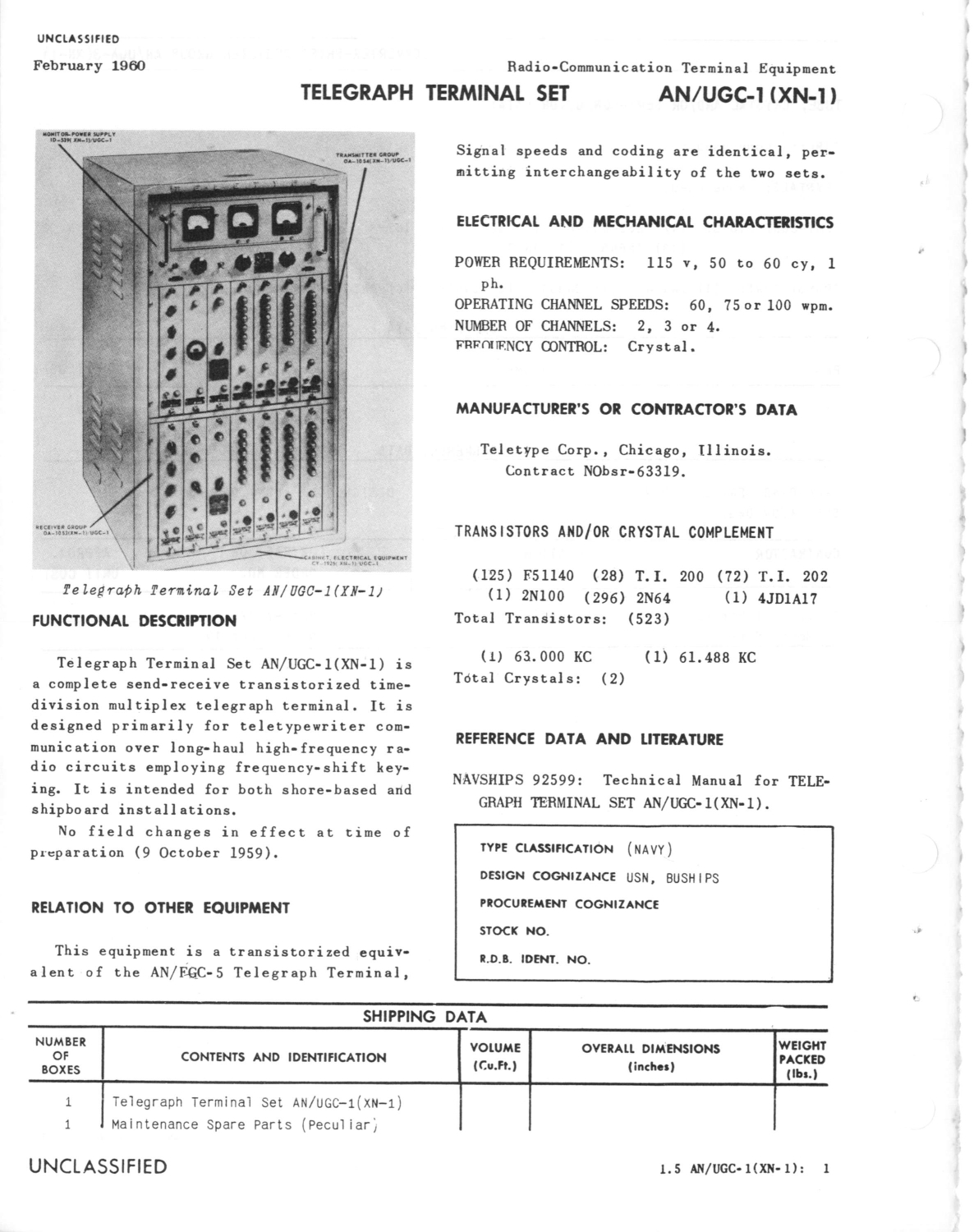
A new high speed telegraph transmitter-receiver in which transistors are used instead of vacuum tubes was recently exhibited in Washington by the Bureau of Ships with the cooperation of the Teletype Corporation, who developed and built the equipment for the Bureau.
The new set is about 1/5 the size and weight of the set it is designed to replace. It provides the same functions as the equipment now in use and the old and the new equipments may be used together. The sets send and receive over four telegraph channels simultaneously at 60 or 75 words a
minute, depending on traffic requirements and radio signal conditions. The transistorized set has the additional capacity to handle 100 words a minute over each of four channels simultaneously.
It is anticipated that the new set will give comparatively trouble-free service, with as many as 10,000 hours of maintenance-free operation being possible. However, the set is so constructed that major units may be opened and serviced while the equipment is operating.
The use of transistors in place of the vacuum tubes makes the advantages of the new set possible.
The transistorized equipment is designed for use in both shipboard and shore installations. Its smaller size and weight make it suitable for use in small vessels and vehicles in which the use of such a system has not been possible up to the present time.
During the recent exhibit, a developmental model of the new set was operated with a production model of the set now in use. The accompanying table gives a comparison of the two equipments.
No major production of the new set is contemplated until final laboratory and field tests have been completed.
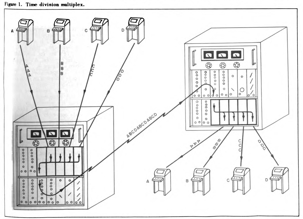 Figure 1. Time division multiplex. |
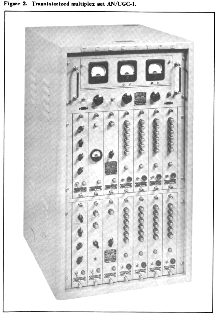 Figure 2. Transistorized multiplex set AN/UGC-1(XN-1). |
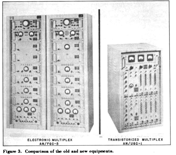 Figure 3. Comparison of the old and new equipments |
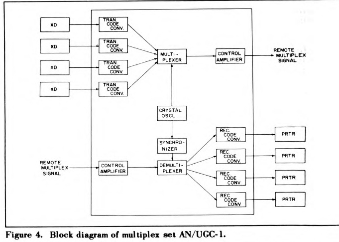 Figure 4. Block diagram of multiplex set AN/UGC-1. |
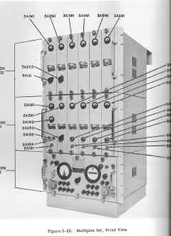
 Figure 5. Time division multiplex set with panel withdrawn, showing ease of operation for servicing. |
- | - |
The success of any undertaking depends to a great extent on rapid and accurate exchange of ideas. Upon this premise are based the development and improvement of communications equipment for the Fleet.
The advent of World War II placed an overpowering burden on the fleet communications system. During the conflict, the system expanded quickly - and in all directions - to meet immediate needs.
Time division multiplex operation of telegraph circuits was first used in the early forties by commercial companies. One commercial system was put in use in the naval shore communication system during the latter part of the war. The equipment was primarily mechanical and was very large and heavy.
Naval Use
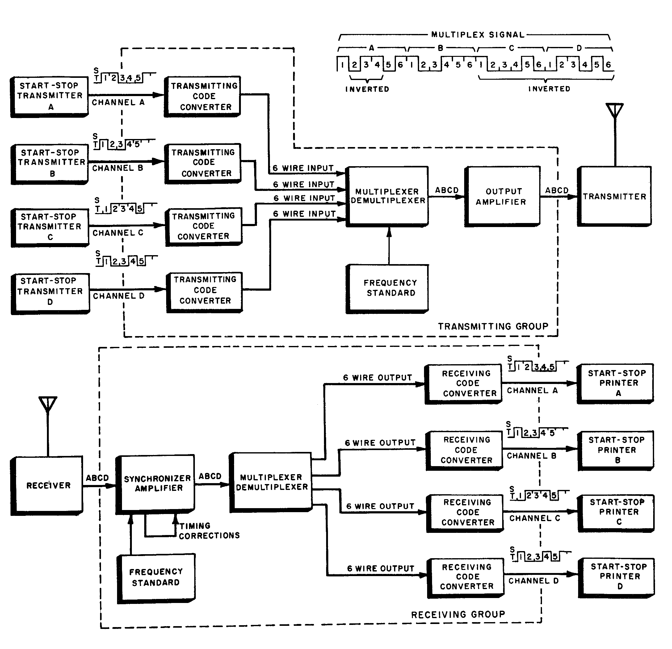
As used by the Navy on teletypewriter circuits, time division multiplex is the transmission of several
teletypewriter circuits on a time-sharing basis in a character by character sequence. Figure 1
shows this in block diagram form.
Information is transmitted into the multiplex equipment simultaneously from four teletypewriters. The same information is then transmitted from one multiplex equipment to the other in a time sequence with one character from each channel at a time. The receiving multiplex equipment then distributes the information to the proper teletypewriter circuits at telegraph speed.
Four characters are therefore transmitted over a single circuit during the time ordinarily required by one.
Shortly after the end of World War II the Navy negotiated for the production of an electronic multiplex equipment that was already under development. The result of the negotiations - the AN/FGC-5 - was introduced in 1950.
Relatively few and minor changes have been made in the AN/FGC-5 since its initial introduction. Hundreds of sets are now in use by all of the armed services and some commercial companies.
Because of its size and weight the AN/FGC-5 is intended primarily for shore station use. However, sets are now installed and in use on board some of the Navy's large communication flagships.
Continually increasing requirements for shipboard communications made evident the need for a shipboard equivalent of the AN/FGC-5. In 1953 the Bureau of Ships entered into a contract for the production of developmental models of a shipboard equipment.
Public Demonstration
The results of the contract—a developmental model transistorized equipment AN/UGC-1 (figure
2) - were publicly presented by the Bureau of Ships at a demonstration on 13 and 14 March 1956 and reported
in the June 1956 Journal.
All of the functions of the AN/FGC-5 are possible with the new transistorized multiplex set AN/UGC-1 and the two sets are completely compatible. However, the AN/UGC-1 includes several features not found in the AN/FGC-5, such as accommodation of 100 words-per-minute teletypewriter equipment, optional tone or d.c. output, and built-in voltage test facilities.
A physical comparison of the two models is given in figure 3 and table 1 that
shows -
• A reduction in weight of 80 percent.
• A reduction in volume of 80 percent.
• A reduction in power needed of 95 percent.
• The elimination of all electron tubes.
The additional features of the new equipment and the seemingly miraculous accomplishments with it were attained by the application of transistors, printed wiring, and other techniques developed by the electronic industry in recent years.
The AN/UGC-1 is a four-channel, send-and-receive, time division multiplex set for use with teletypewriter circuits. A block diagram is shown in figure 4.
Operating speeds of 60, 75, and 100 words a minute on each channel are available in this equipment. A change in the operating speed of the entire equipment may be made in a very few minutes by operating several switches and readjusting the code converter oscillators.
Crystal Oscillator
Direct-current, neutral, start-stop teletypewriter signals are fed into the transmitting code converters
where they are momentarily stored. A crystal oscillator drives the multiplexer that reads out a character
from each code converter in turn. The multiplex signals are then amplified in the control amplifier and
fed onto a wire line or radio circuit.
The output signals may be either keyed direct current or an on-off keyed tone of about 2500 cycles a second. These signals are used either on wire lines between terminals or to key radio transmitters for long distance communications.
On the receiver side of the equipment, the multiplex signal is fed through the control amplifier and into the demultiplexer. The demultiplexer is driven from the synchronizer which derives its basic operating frequency from the oscillator in the transmitting portion of the equipment.
The demultiplexer "routes" the individual teletypewriter signals to their respective receiving code converters. The signals are stored momentarily in the code converters, and are then regenerated and transmitted to the teletypewriter equipment in the same start-stop form, and at the same speed as they were received.
Phasing
The transmitting and receiving equipment is maintained in synchronism by the use of very stable
crystal oscillators. The receiving equipment is constantly monitoring the received signal and correcting
the drive frequency of die demultiplexer to keep it in synchronism with its transmitter.
Phasing—the distribution of the proper information to the proper channel—is done by the recognition of an "idle" or no transmission signal by the "A" channel receiving code converter. With traffic interrupted on "A" channel at the transmitting terminal, operation of the phasing switch at the receiving station will cause the receiving, equipment to step itself automatically into proper phase relationship with the transmitter.
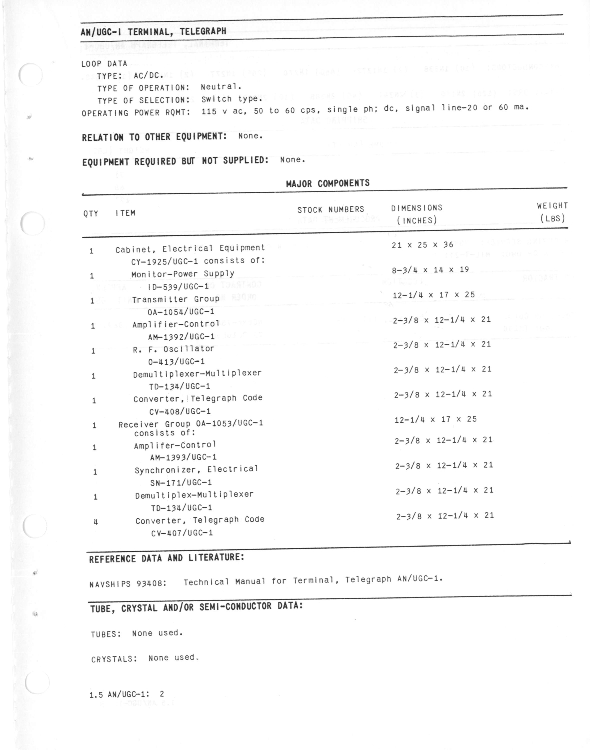
Housing Cabinet
In the AN/UGC-1, a receiver group, a transmitter group, and a power supply are all housed in a
single cabinet 36 inches high, 21 inches wide, and 25 inches deep. The cabinet is made of heavily
reinforced aluminum and weighs about 60 pounds. Through a hinged rear door, signal line terminals and
inter-connecting terminal boards are accessible. Also, side and rear cable entrances are provided.
The transmitter and receiver group enclosures are each in a special aluminum alloy box designed for standard rack mounting. Drawer units are suspended from the top of the box, and held locked in operating positions by thumb screws.
A novel collapsible cable assembly is provided so that each unit may be withdrawn for test without interrupting the circuit (figure 5). Stops are provided to halt the travel of the drawer at its test position. Also, the drawers may be removed from the box when they are to be repaired.
Cable Assemblies
The bellows cable assemblies, as they are called, end in interconnecting terminal boards at the rear
of the box. The assemblies are attached to a hinged door that may be released and be let down for
inspection and test purposes.
The power supply is a separate electronic chassis and is mounted in the upper portion of the cabinet. Interconnections between the power supply and the other units of the equipment are made by the use of flexible cables with connectors on either end. These cables provide all direct connections between the transmitter and receiver units.
The power supply is a simple unregulated supply with germanium rectifiers. Meters and switches are included to monitor levels, voltages, and currents as required.
Each major drawer unit, except the power supply, is an assembly of electronic components that includes transistors, germanium diodes, resistors, and capacitors. Components (except transistors) are mounted between terminals on etched circuit cards that in turn are mounted on both sides of a vertical etched-circuit center board or "cable" board. Transistors are plugged in.
Brackets are provided for mounting most controls and switches. Each unit has a front panel on which are mounted all operating
controls and indicators. Aluminum side plates, that may be removed for service and testing, protect components.