1950's-60's vintage
Originally RATT FSK signals were Mark High (center freq +425 Hz) and Space
Low (center freq -425 Hz). This changed to Mark Low and Space High in the early
1970s (?).
Originally RATT AFSK tones were centered at 2550 Hz (2975 M, 2125 S). This
changed to 2000Hz center in the late 1960s (?).
Please send email
if you have more info about these changes
From a 1989 Coast Guard Manual -
CV-3883/UG Converter Keyer AFSK Frequency Adjustment Information
If you have ever aligned a CV-3883/UG Dovetron you probably noticed the absence of Navy and Coast Guard frequency shift information. Το complicate matters, prior to about 1972 the Navy's Normal mode of operation was wide shift RATT with the MARK tone HIGH and the SPACE tone LOW.
The Navy made Reverse keying MARK tone LOW and SPACE tone HIGH the normal mode of operation in 1972 but stayed with wide shift. On existing signal conversion equipment radio operators would put the RATT converter in the REVERSE mode to correct the output logic of the received now MARK LOW signals.
Technical manuals for older Navy equipment reflect the original Mark High Space Low convention e.g. the CV-2460/SGC. Manuals for newer equipment e.g. the AN/URA-17E reflect the Mark Low convention.
The Coast Guard uses Space High Mark Low narrow shift keying as its normal mode of operation. Some old timers argue that this is REVERSE keying, but the bottom line is that Mark Low is the standard to which we align our CV-3883/UG in the Normal mode of operation.
Recent discussion on the reasons for the changes -
After Daniel K6YIC found some relevant NATO
documents, John K9WT commented - This is very interesting material, and thanks for digging it up. The documents indicate that the U.S. military switched to MARK-low FSK for compatibility with new STANAGs prescribed by its European NATO partners. The documents do not indicate just why the European countries chose MARK-low, so this remains a mystery, at least to me. It was either an arbitrary choice, or based on some prior European convention I'm unaware of. Both MARK-high or MARK-low shift polarity provide equal performance, and one has no advantage over the other, provided everyone agrees on a convention.
Memorandum SGM-223-61 suggests the NATO Standing Group prescribed MARK-low as the standard in 1961, but was then informed that the U.S. already had a standard which was the "conjugate" of this (that is, MARK-high). The memorandum states the U.S. would accept the new STANAG if the following sentence was added: "For universal compatibility, keying polarity reversing facilities will be provided in both receivers and transmitters, to permit operation on either the keying standard prescribed in this STANAG or on its conjugate which is the U.S. standard."
As it happened, the U.S. did not provide reversing facilities for BOTH transmit and receive in all their FSK equipment. Some FSK modems, like the MD-522, provided only reversible receive capability, and transmit was fixed at MARK-low. This met the NATO standard yet maintained compatibility with the MARK-high AN/GRC-46 (also reversible on receive) and other legacy U.S. equipment.
The other documents are primarily concerned with setting standards for a new generation of synthesized SSB equipment which would be used with AFSK modems, and has some bearing on the choice of tone center frequency. Of interest here is IMSM-0216-67, which sets requirements for SSB filter characteristics, including passband width, ripple, group delay, and stopband rejection. A BW of 2700 Hz was chosen, extending from 350 Hz to 3050 Hz, minimum, with +/- 2 dB ripple.
The upper band edge of earlier military SSB equipment was a bit wider, typically at 3250 Hz, and 2550 Hz tone center was often used (upper tone 2975 Hz). This was cutting it too close for the proposed new NATO standard SSB radios, so the tone center was reduced to place it nearer the passband center, which was 1700 Hz. However, 2000 Hz was an alternative AFSK tone center already in use with SSB equipment having narrower filters, so this was chosen instead. Again, either 1700 or 2000 Hz tone center would have worked equally well from a purely technical viewpoint, and the choice was dictated by a prior convention.
So the transition to MARK-low FSK can be traced to a European NATO standard, and the use of 2 kHz tone center for AFSK equipment was chosen for compatibility with new NATO SSB radios with an upper passband limit of 3050 Hz.
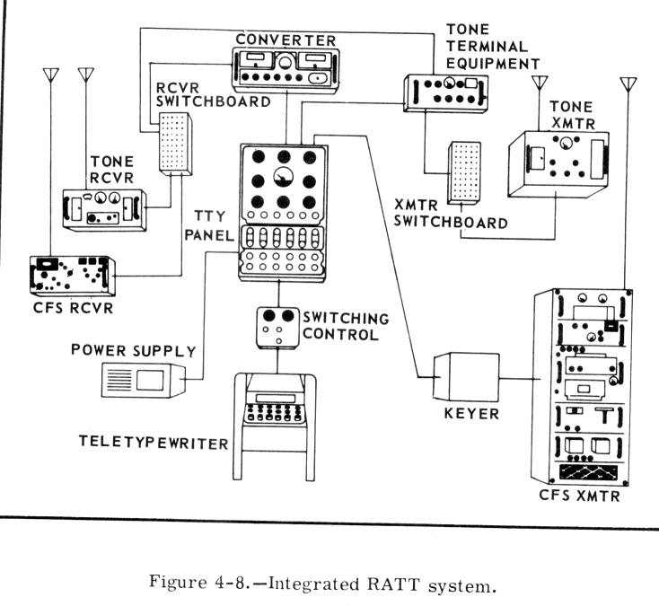
TUNING IN A SINGLE CHANNEL RFCS RATT SIGNAL
Many good RATT signals are so degraded at the receiver that they become either unreadable or take too many hits to be of much use. This is often the result of improper tuning of the receiver. The intent of this article, therefore, is to provide some understanding of the required tuning procedures for proper reception of RATT signals.
Single channel teletype transmissions in the MF and HF bands use a radio frequency carrier shift (RFCS) of 850 Hz, or +/- 425 Hz with respect to the assigned frequency. If the assigned frequency were 8694 kHz, this would be the center frequency to be radiated from the transmitter. Two signals would be transmitted alternately, and neither of the signals would be 8694 kHz . The teletype mark signal would be transmitted 425 Hz above the center frequency of 8694, and the space signal would be transmitted 425 Hz below the center frequency. This means that the transmitter would develop a mark signal of 8694.425 kHz and a space frequency of 8693.575 kHz . Only these two frequencies need be received, and the receiver should be set to receive them in the center of its reception "window " or passband.
Receivers used for reception of RFCS RATT signals vary in their details, but in general the receiver should be tuned in the following manner:
1 . First set the receiver passband to a fairly narrow value, on the order of 1 kHz. Tune the receiver to the frequency of the desired RATT signal by observing the receiver INPUT or CARRIER LEVEL meter. Ignore the received pitch at this point, or better yet, turn the BFO off until the signal is tuned so as to center in the receiver passband. Then lock the main tuning dial if possible.
2. Turn on the receiver BFO and set its frequency 2.0 kHz BELOW the center of the receiver pass band (2550 Hz for receivers used with older, unmodified TTY Terminal Units). This value is used because single-channel TTY converters use a passband centered at 2 000 Hz in present units, or 2550 Hz for older units. Some receivers have an "FSK" mode in which the BFO is automatically set to the proper value by the mode switch. Other receivers are merely aligned so that the "zero beat" position of the BFO falls in the center of its travel; for these receivers, the proper BFO setting for RFCS operating must be found using step 3. Once the proper point on the BFO control is found, it is a good idea to mark it as the "FSK" setting.
3. Place the receiver BANDPASS control in the 2 kHz position ( note that RFCS RATT emission is 1.24F1 ) . With sufficient receiver output to drive the TTY converter, slowly and carefully tune the BFO (called "FREQUENCY VERNIER " in some receivers) until the two horizontal lines on the TTY converter oscilloscope are equal distances above and below the center reference line on the CRT graticule. When this condition exists, the receiver is properly tuned, with the received signal in the center of the receiver passband as well as in the center of the TTY converter passband. The common failing is to leave the receiver BFO at its center or zero beat position and tune the main dial so that the RATT signal is 2.0 kHz off frequency with respect to the center of the receiver pass band. The fallacy of this procedure should be obvious if you think about it.
4. If the TTY printer now "prints inverted", the order of sidebands has been inverted in the receiver. This happens in some receivers on some of their bands. When this is the case, there are two alternatives available: either repeat steps 2 and 3, resetting the BFO ABOVE the center frequency rather than below, or else operate the TTY converter NORMAL/INVERT switch to the INVERT position.
=======
A field change has been developed for converting TTY terminal units to a center frequency of 2000 Hz instead of 2550 Hz so that those receivers that now cannot be offset by 2550 Hz in a stabilized mode can be operated with a stabilized 2.0 kHz offset. TTY terminal units so converted will copy 2425 Hz as a mark and 1575 Hz as a space, which are the values currently used by the AN/URC-32, the AN/ARC-94, and some others. In order to produce reliable copy of RFCS RATT signals, a receiver should be operated in a tuning mode that provides best stability and accuracy. By using TTY terminal units centered on 2.0 kHz, the associated receiver can be operated at stabilized increments of frequency.
For use with unmodified older TTY terminal units, some receivers such as those of the AN/WRC-1, AN/URC-3 2, and AN/URC-35 employ BFO (carrier) injection only at the dial frequency and therefore the tuning cannot be offset by the required 2550 Hz while the receiver is in a stabilized mode. For operation of the R-1051/URR receiver (Part of the AN/WRC-1) with 2550 Hz terminal units, the following procedure will be helpful:
1 . The receiver "window " or reception pass band is offset 1.5 kHz from the BFO (and the dial reading) by selecting the SSB mode. For single channel RFCS, the mark/space relationships are correct when upper sideband is selected.
2 . Switch the main tuning to VERNIER and set it for 3 kHz BELOW the assigned frequency. The R-1051/URR receiver frequency control is independent of the transmitter, which is set 2.0 kHz below the assigned frequency channel for RFCS operation.
3. Tune the incremental tuning to approximately 450 Hz and adjust as previously described for a appearance on the TTY converter scope.
This method of receiver tuning is preferable to the use of the CW mode because of the higher stability of VERNIER tuning and the better selectivity of the SSB mode. Using the receiver in this manner also provides better CW reception than that of the CW mode for the same reasons. The R-1051/URR bandwidth is 7 kHz in the CW and the AM modes , and 3.2 kHz in the SSB mode . The narrower selectivity in the SSB mode provides approximately a 2-to-one improvement in signal-to-noise ratio.
Because the AN/URC-32 uses only one stabilized oscillator for both transmitting and receiving, it cannot be used in the transceive mode with a 2550 Hz TTY converter.
AFTS (Audio Frequency Tone Shift) RATT NETS
AFTS terminal units of the AN/SGC-1 series and the newer CV-2460/SGC are reliable and "nettable"
items of the ship's TTY system. They are versatile equipments ideal for ORESTES nets within a task
group or task unit. For this reason, shipboard operators and technicians should understand their use
and features in order to get the most from them. There is no better way to learn the capability of an
equipment than by actual operation. This can be done easily by operators who want to become
proficient, using an authorized UHF drill frequency.
The AN/SGC-1 and the CV-2460/SGC series AFTS terminal units are DC-to-audio converters in the transmit mode. They receive DC from a teletype loop and convert it into audio frequencies for modulation of a radio transmitter (note: the transmitter must be in the VOICE mode, not MCW mode). For narrow audio frequency shift the high audio tone is 700 Hz and the low tone is 500 Hz. For wide shift (CV-2460/SGC only) the high tone is 2425 Hz and the low tone is 1575 Hz. Normally the high tone indicates a mark and the low tone indicates a space, but this relationship can be reversed at will.
In the receive mode the equipments are audio-to-DC converters. Audio from a receiver is fed into the terminal unit. The signal could have been transmitted either as AFTS or RFCS, as long as the receiver converts it to the proper tones.
Each terminal unit has a mode selector switch which can place it in constant XMIT or constant RCVE, or an AUTO position which permits it to switch to receive whenever a signal arrives from the receiver or go to transmit, keying and modulating the transmitter, whenever the local TTY keyboard is operated. This is ideal for net operation. The CV-2460/SGC has full duplex capability, permitting simultaneous use of transmit and receive functions.
The AFTS terminal units interface with other equipments via three basic inputs/outputs other than the
AC power connection:
1. A DC circuit which is looped through the TTY patch panel.
2. An audio input into which a receiver feeds tones.
3. A keying and modulation output by which the terminal unit controls a transmitter.
The equipment is very simple to use, and will function effectively provided that compatibility is maintained with the other parts of the system. The first point of concern is adjustment of the receiver that is used to receive the radio signals. If the output of the receiver is noisy when no actual signal is being received, the noise will trigger the terminal unit into a RCVE condition and it will not go automatically into the XMIT condition when the local teletype keyboard is operated. The noise output of the receiver must be kept low or squelched off during the time no signal is being received. Ideally, the no-signal noise level should be about -30 dB when the receiver output is set to supply audio tones at 0 dB. Noise from the receiver must not be allowed to trigger the terminal unit into a RCVE condition when no tones are being received. The second point is based on the transmitter modulation level that has been set on the ship. If all radiophone remotes are set to furnish -10 dB modulation level into the transmitter speech amplifiers, and the audio output of the AFTS terminal unit is set to furnish 0 dB, overmodulation will occur which will cause distortion and interference. If the output of the terminal unit is set for less than the standard RPU (Remote Phone Unit) modulation output, undermodulation will occur which will decrease the reliable communication range between ships. If the transmitter has a clipper-filter in its speech amplifier, this circuit should be turned off for tone operation; AGC (or AVC) circuits should be left on. The audio input and output levels from the TTY terminal unit should be set to furnish the same levels into the audio distribution system that the remote phone units furnish. Refer to Transmit-Receive Panels and Remote Control Units under Subsection 1-9 of the EIMB.
Don't overlook the "spread" between mark and space frequencies; 700 Hz and 500 Hz for narrow shift AFTS gives a spread of 200 Hz. The normal spread for single channel RFCS in the low frequency bands is 170 Hz. Either terminal unit can be used to copy narrow-shift RFCS of the type used on low frequencies when the associated receiver is set up properly. Just tune up the receiver to the desired signal as previously described in Tuning in A Single Channel RFCS RATT Signal, except that the receiver BFO is offset by -600 Hz rather than 2000 Hz (or 2550 Hz). The audio output from the receiver will be near enough to 700 Hz for mark and 500 Hz for space that the terminal unit can copy it. The CV-2460/SGC provides the additional capability of being able to copy wide shift RFCS single-channel circuits.
Either AFTS terminal unit can also serve as a part of single-channel UHF-to-HF relay circuits. It converts the AFTS signals received on UHF into a keyed DC loop current, and the loop current in turn operates the wide-shift RFCS circuits of the HF transmitter. Care must be exercised if the terminal unit and the HF transmitter have separate loop power supplies. The two power supplies must not be patched together. If such a risk exists, one solution is to wire the terminal unit to a miscellaneous jack on the TTY patch panel rather than to a looping jack. It can then be patched into either loop as required.
When the receiver input levels and the modulation output levels are properly set, and the mark and space frequencies are correct, the AN/SGC-1 and CV-2460/SGC series terminal units will provide reliable and versatile communications.

Early FSK keyers - FSA, FSB, FSC
TH-39/UGT & TH-39A/UGT (TMC TIS-2 & TIS-3) - AFSK keyer
Includes brief descriptions.
Also see CQ magazine September 1972, page 83 (avail at http://hamcall.net/cq)
This is a great email list for TTY and RTTY information
http://mailman.qth.net/mailman/listinfo/greenkeys
Check out the greenkeys archives