"Carrier Frequency Shift Transmitting System"
- BuShips Journal December 1956
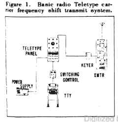
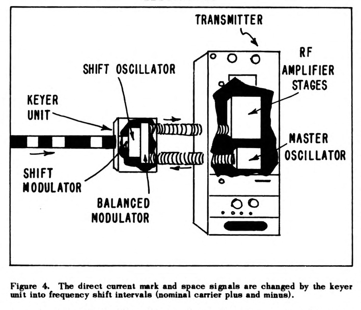
Figure 1. Basic radio Teletype carrier frequency shift transmit system. |
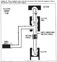
Figure 2. One complete loop with the electronic flow from the negative side to
the positive side of the power supply. |
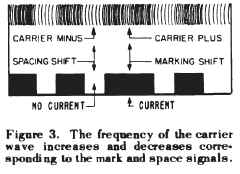
Figure 3. The frequency of the carrier wave increases and decreases
corresponding to the mark and space signals |

Figure 4. The direct current mark and space signals are changed by the keyer
unit into frequency shift intervals (nominal carrier plus and minus). |
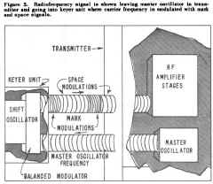
Figure 5. Radio frequency signal is shown leaving master oscillator in
transmitter and going into keyer unit where carrier frequency is modulated with mark
and space signals. |
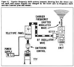
Figure 6. Carrier frequency shift system transmit showing how the direct
current mark and space signals are changed by the keyer unit in frequency shift
intervals (carrier plus and minus). |
"Carrier Frequency Shift Transmitting System"
By Joseph J. Fisher, Communication Section,
and Victor L. Kebler, Electronics Publications Section, Bureau of Ships
This is the fourth in a series of articles that describe the Navy's radio Teletype systems and how they
operate. The previous articles are in the Bureau of Ships Journals of November 1955 and April and
September 1956.
The Navy's radio Teletype systems afloat are designed to provide fast, reliable, printed
communications over a great variety of distances. A complete installation includes a tone modulated system for
short-range signals, and a carrier frequency shift system for long-range communications.
This article on the transmitting components of the latter system is primarily about the
keyer-transmitter combination and the nature of the signals it sends out. The keyer
may be built into the transmitter or it may be a separate component. In this article it is shown as a separate
component.
Figure 1 shows the basic components used for transmission of the carrier frequency shift system.
These components are: Power supply, Teletype panel, switching control, and teleprinter, as well as the
Keyer and transmitter.
The direct current furnished by the power supply is known as the looping current. The term "looping
current" originated from the series or loop path that the current followed through the equipment components.
In figure 2 the current can be traced from the negative terminal of the power supply through these
components back to the positive terminal of the power supply.
The teleprinter may be visualized as a switch that opens and closes the looping circuit. This feature
causes on-and-off pulses of the direct current. These pulses are known as "marks" and "spaces."
The teleprinter's direct current signal of "marks" and "spaces" moves through the switching
control and one channel, or loop, in the Teletype panel, and then on to the keyer at the transmitter. In the
keyer, the signal is changed into a corresponding sequence of shifted frequencies that are impressed on
a radio carrier wave for transmission.
The same message is in two types of signals—direct current and frequency modulated radio waves. The
relationship is readily seen when the radio signal is paralleled with the corresponding Teletype signal
(figure 3). Basically the transmitted signal is similar to the signal transmitted by the familiar FM
radio stations.
The marks and spaces are formed by frequency shifts either higher or lower than the carrier frequency which is never transmitted.
The mark is the carrier frequency plus the modulating frequency - called a marking shift. The space
is the carrier frequency minus the modulating frequency - known as a spacing shift. Thus the frequencies
actually being transmitted are always higher or lower than the carrier frequency from which the shift
is reckoned.
The carrier frequency itself never reaches the antenna because the keyer receives the carrier frequency
from the transmitter and the direct current on-and-off pulses from the teleprinter. These pulses
automatically shift the basic frequency to "plus" for marks and "minus" for spaces. Then the frequency shifted
carrier wave goes back to the transmitter.
Changes
The changes take place in the following manner:
- In the transmitter, a master oscillator generates the basic radio frequency that is fed into a balanced
modulator in the keyer. Coupled to the balanced modulator is the shift oscillator controlled by its own shift
modulator stage (figure 4).
- As the direct current mark and space pulses feed into the shift modulator, it actuates the shift
oscillator to produce a higher frequency for mark or a lower one for space. The balanced modulator
correspondingly increases or decreases the carrier frequency wave to produce
the frequency shifted carrier wave that is fed back into the amplifier stages of the long range
transmitter (figure 5).
- Transmitter operational changes in the master oscillating frequency do not affect the frequencies of the
shift oscillator. Hence, it is the keyer unit through which the signal is converted and the frequency is
shifted.
To summarize, in the transmitting function of a carrier frequency shift system for teletype communication,
direct current pulses from the teleprinter pass through the switching control unit and Teletype panel to
the keyer, where the basic oscillating radio frequency from the transmitter is changed to a
frequency shifted carrier wave, and fed back into the transmitter, amplified, and
then fed to the antenna where the power is radiated into the ether (figure 6).
The same message has two types of signals in the system. The frequencies transmitted are always
increases or decreases of the basic carrier frequency that is never transmitted as such.
This is the complete basic pattern of operation that applies to this group of equipment. In this type of
transmitter, the keyer is a built-in component, but it may be a separate unit.
This is the complete Navy carrier frequency shift transmitting system for reliable long-range
radio-teletype operations.