See below for two articles on using the 28RT
Also see useful article in CQ May 1967 page 90
Video of my 28RT in operation
28RT Specifications Brochure - download 5 MB pdf - thanks to Don Robert House
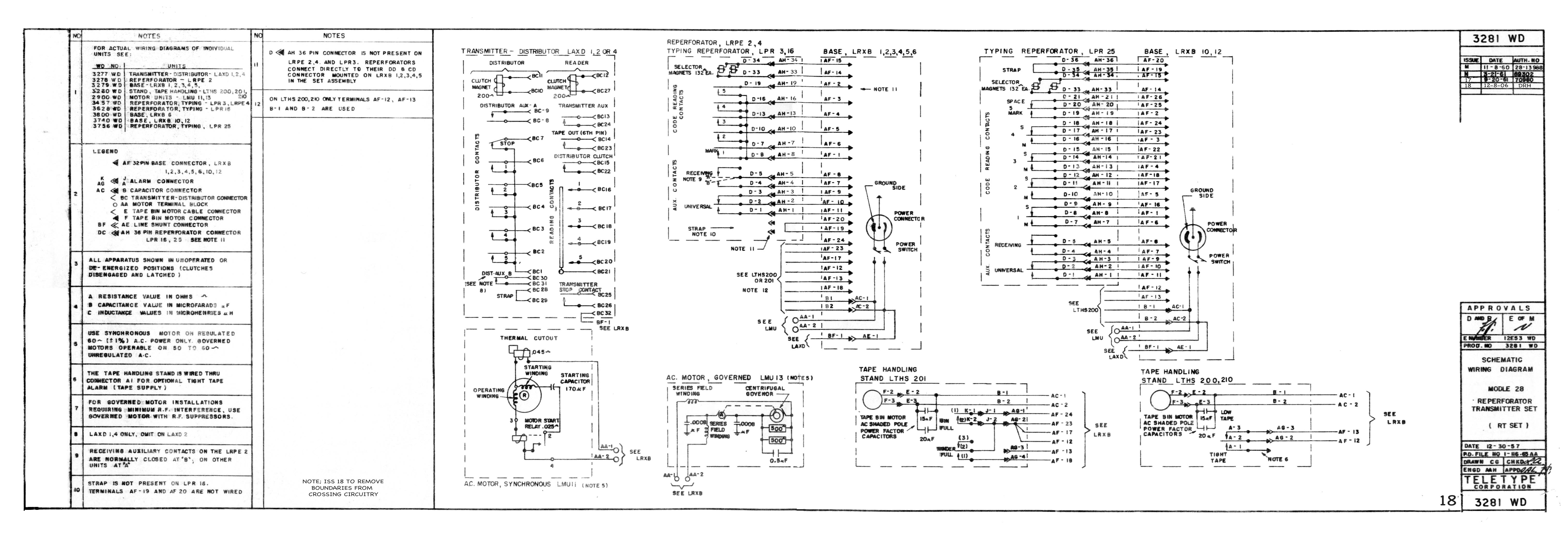
28RT Wiring Diagram (3281WD) - thanks to Don Robert House
28RT Installation & Adjustment (Specification 5875S) - download
1.5 MB pdf
28RT Adjustments & Lubrication - LRXB Base, LTHS Stand (Bulletin 248B) -
download 9.7 MB pdf
28RT Parts - LRXB Base, LTHS Stand, LBAC Cabinet (Bulletin 1168B) - download
11.2 MB pdf
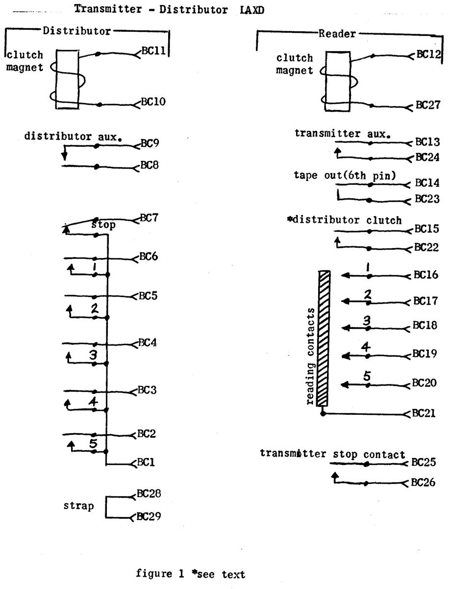
LAXD Transmitter-Distributor Description & Theory (Bulletin 251B) - download
3.7 MB pdf
LAXD, LCXD Transmitter-Distributor Adjustments & Lubrication (Bulletin
252B) - download 14.7 MB pdf
LAXD Transmitter-Distributor Parts (573-127-800TC) - download
2.2 MB pdf
(all
the above thanks to David Christ & John Poulton)
LAXD, LCXD Transmitter-Distributor Adjustments & Lubrication (Bulletin 252B) - download
3/58 version, download 11/68
version
LAXD Transmitter-Distributor parts diagrams (Bulletin 271B) - download
1.5 MB pdf
(thanks to
Tom Tillson)
|

|
|
|
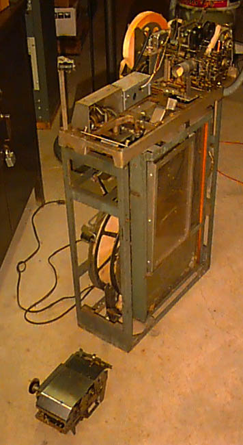
My 28RT - 12/2009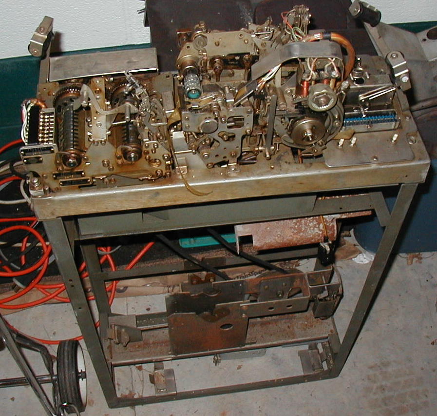 |
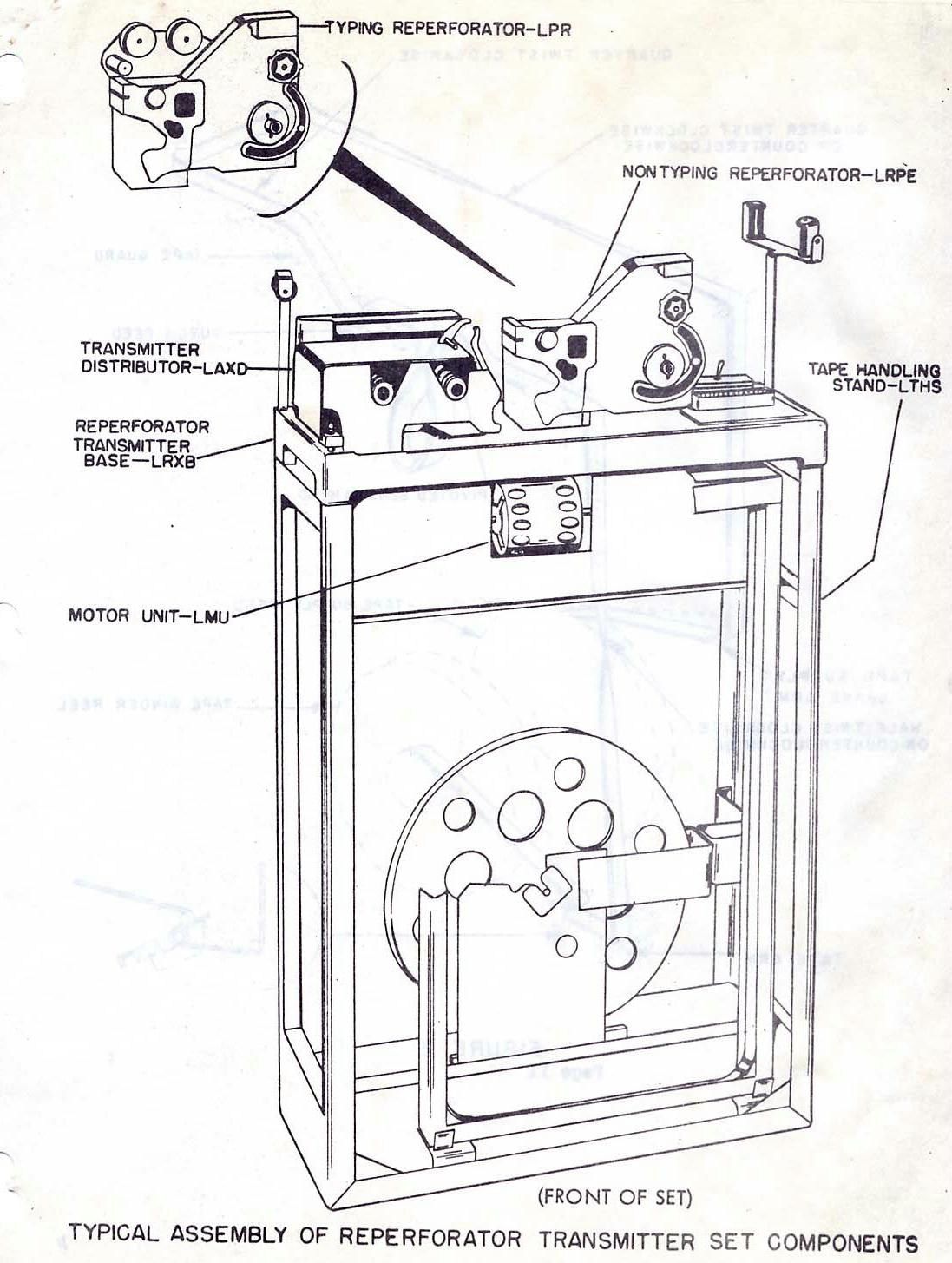
LAXD1 Transmitter-Distributor 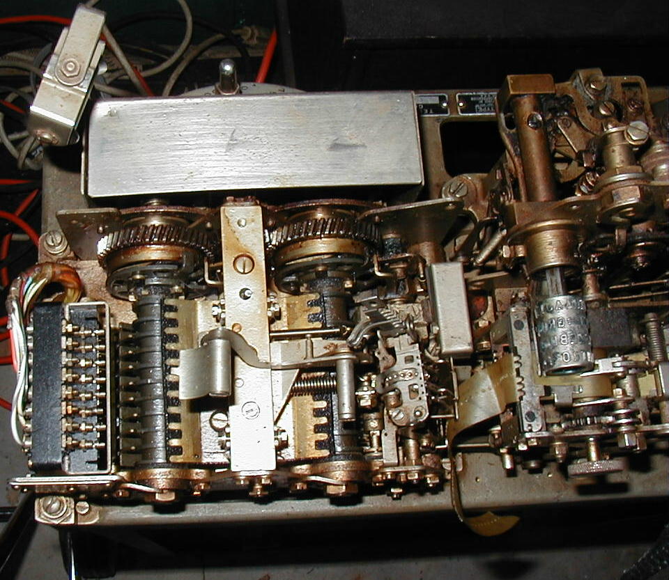 |
LRXB5 top deck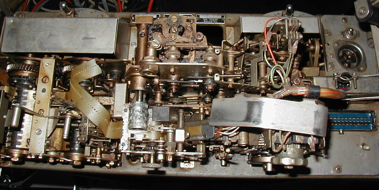 |
LPR3ARE Reperforator 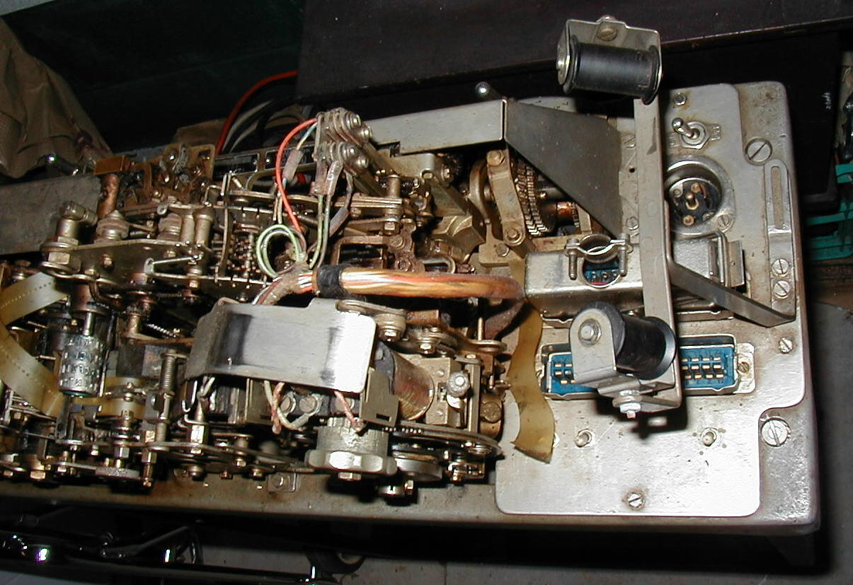 |
Tape Reel holders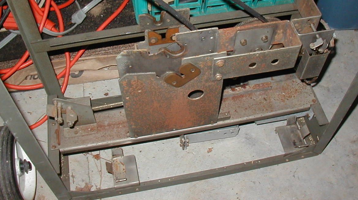 |
Reperf 60-75-100 transmission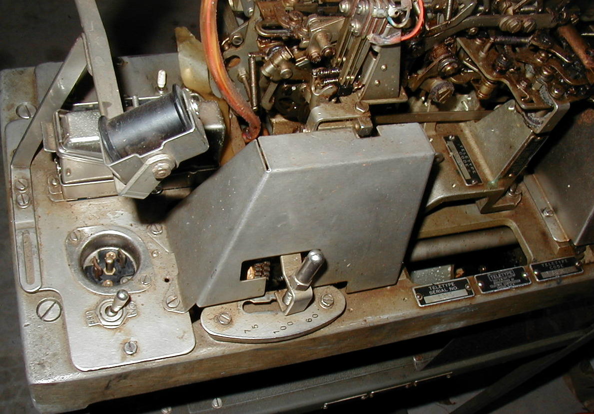 |
TD 60-75-100 transmission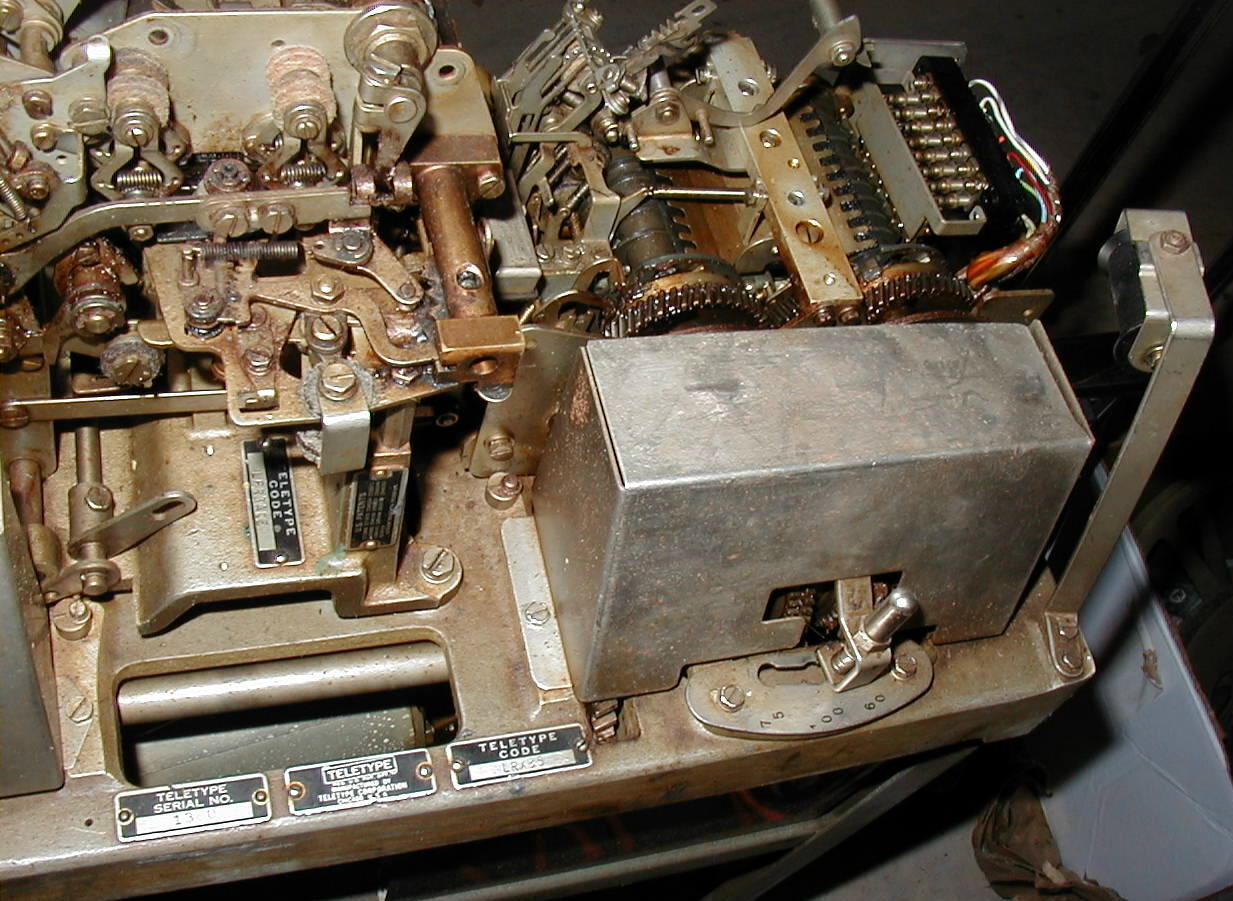 |

|
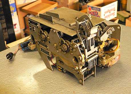
LAXD1 Transmitter-Distributor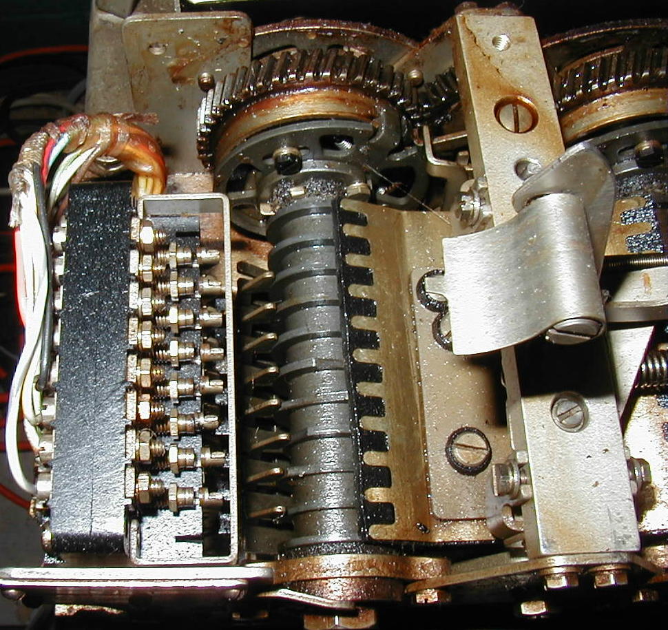 |
LAXD1 Transmitter-Distributor |
LPR3ARE Reperforator 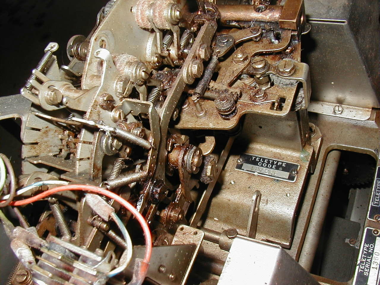 |
LPR3ARE Reperforator 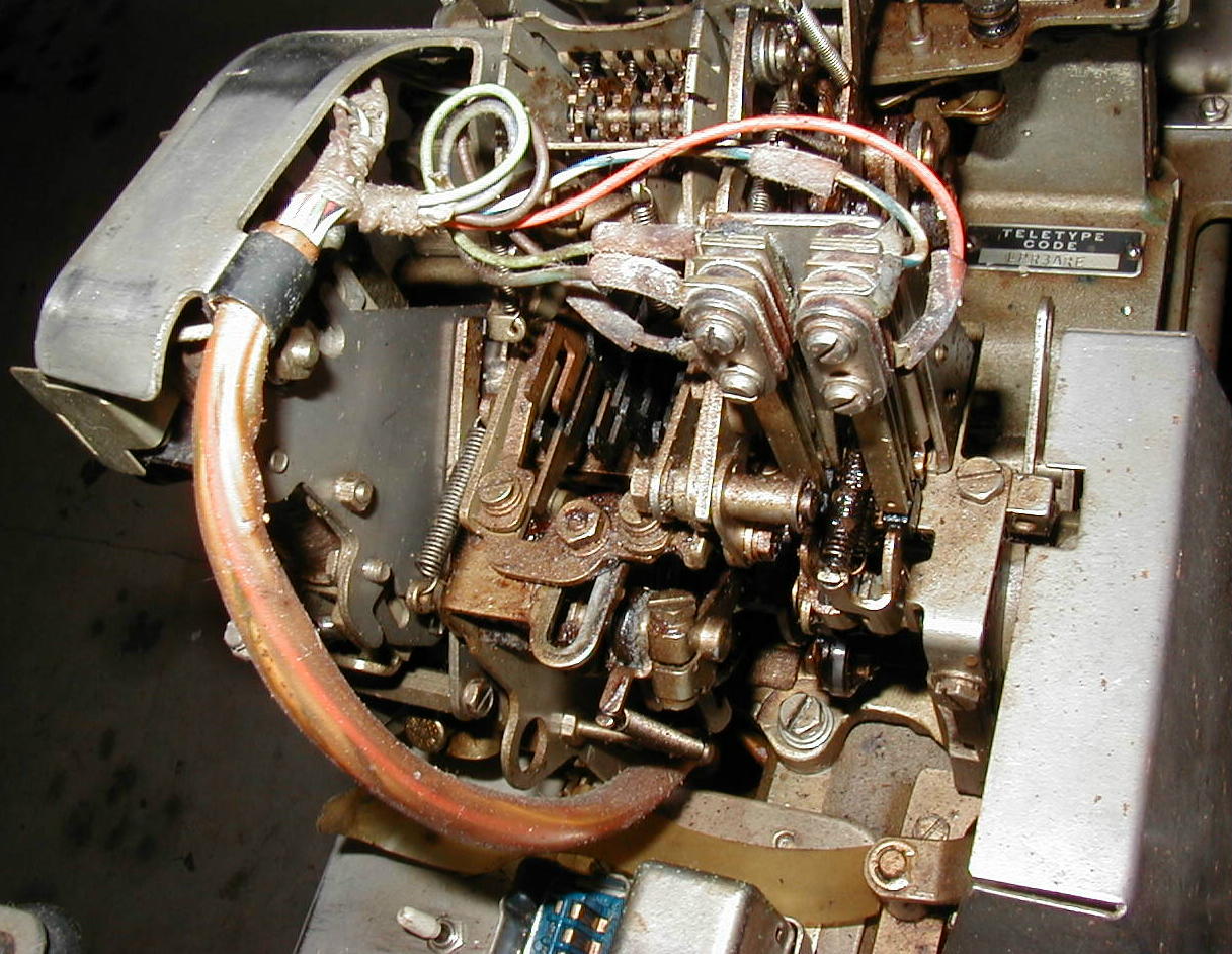 |
LAXD1 Transmitter-Distributor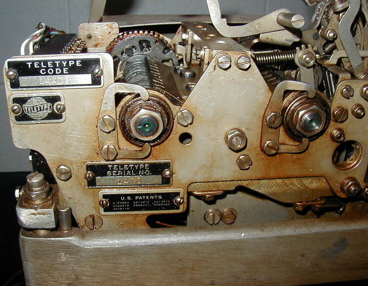 |
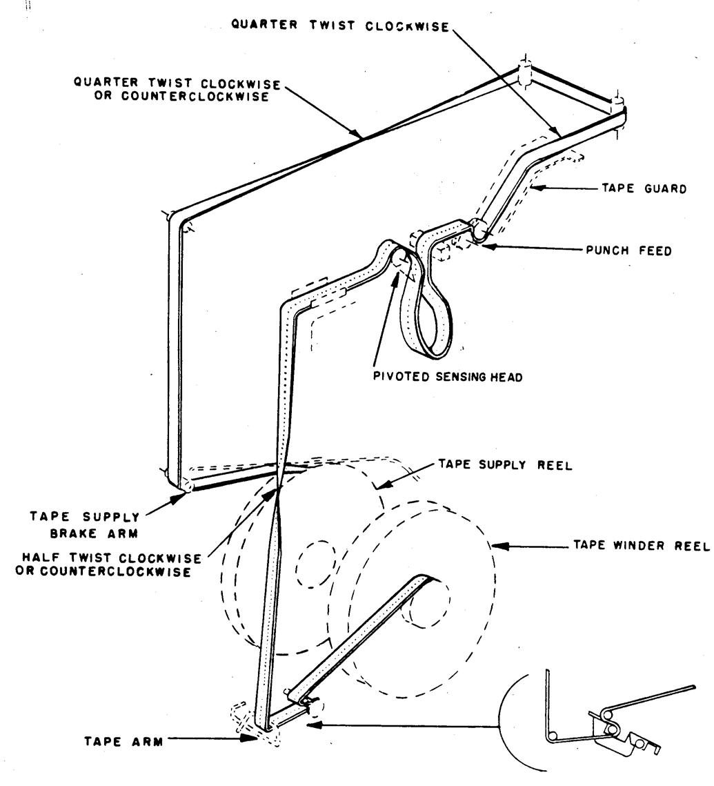
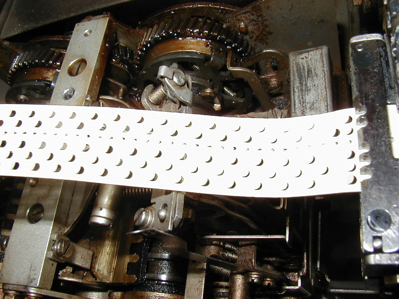
Reperf tape punch feeding TD head |
Tape take-up and feed reels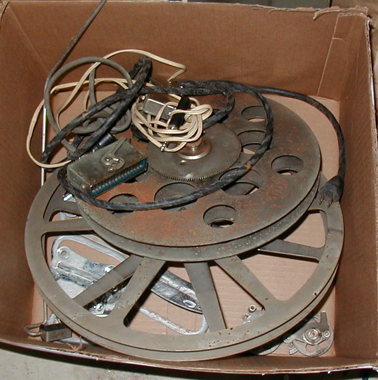 |
Tape bin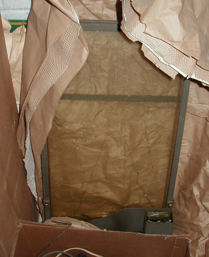 - - |
Another LAXD1 |
 |
-- | -- |
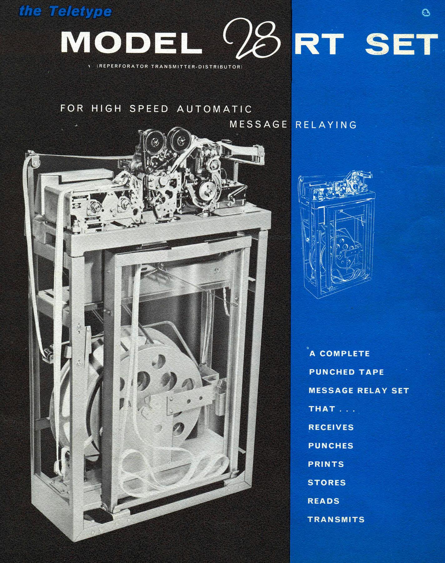
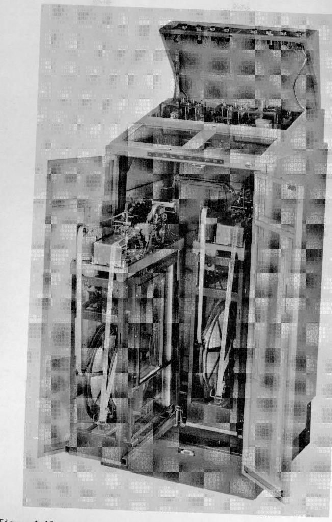
| April 1959 - The addition of an all-new automatic message relay set to the Model 28 line of communications equipment has been announced by Teletype Corporation, Chicago, Illinois. The new unit, called the Model 28 RT (reperforator transmitter-distributor), is a high capacity, self-contained, punched tape message relaying facility for receiving wire signals at speeds ranging from 60 to 200 words per minute, converting them into perforations in paper tape and transmitting them at the same or another speed to local or remote receiving stations. It is designed for a variety of uses in communications, data processing and automation - included in these are applications as an input-output speed converter, intermediate message storage, business machine communications linkage, automatic data accumulator, and control device for automated factory equipment. The RT Set features three message relaying devices: ( 1 ) a receiving unit for accepting income wire signals, punching and printing the signal data on a standard 11/16 in., 5-level "common-language" paper tape; ( 2) a sending unit for reading and translating the taped data into electrical impulses for transmission either cross-office or cross-country; ( 3) and a tape handling unit with tape supply reel, intermediate tape storage bin and tape winder reel. A choice of three tape punching components are available for adapting the RT Set to a wide range of individual application requirements - a typing and a non-typing tape punch for accepting sequential (serial) signals and a non-typing tape punch for accepting parallel signals. A special-design twin-shaft sending component features transmission of sequential or parallel-wire signals and automatic end-of message shut off. Receiving and sending units will operate at the same or different speeds, e.g., receive at 60 WPM, transmit at 100 WPM. Model 28 RT Sets may be mounted singly or in pairs in a newly designed universal cabinet featuring on-off switches, tape warning lights and other facilities essential for external control of equipment within the cabinet. |
|||
 |
 |
 |
Lamp transformer and lamp sockets in base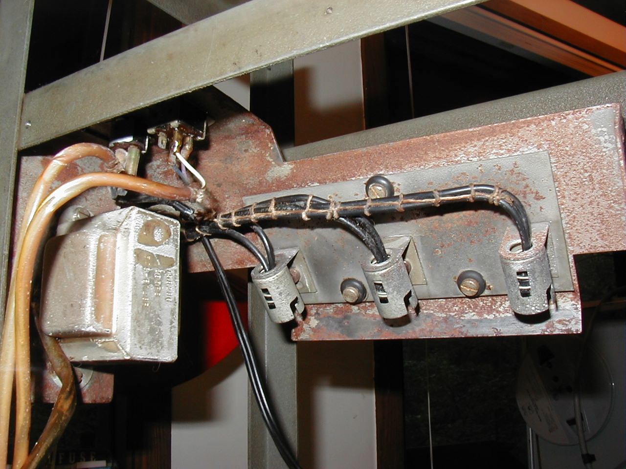 |
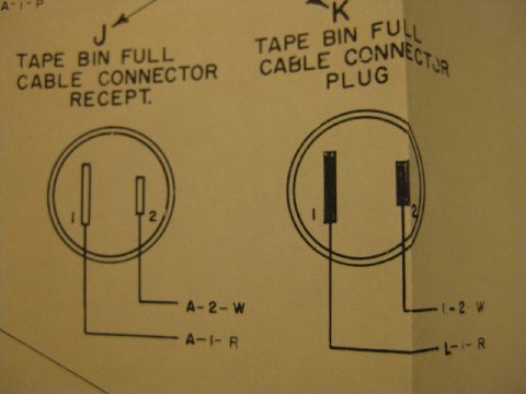
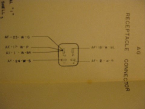
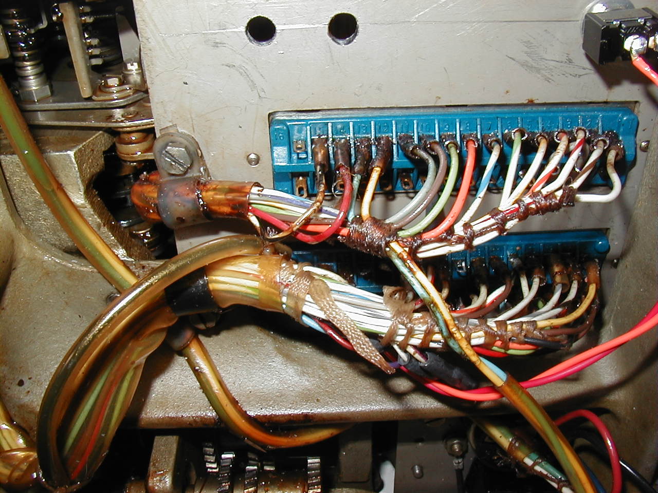
| Connectors from base to top deck - capacitors on left, tape switch in middle, lamp transformer on right 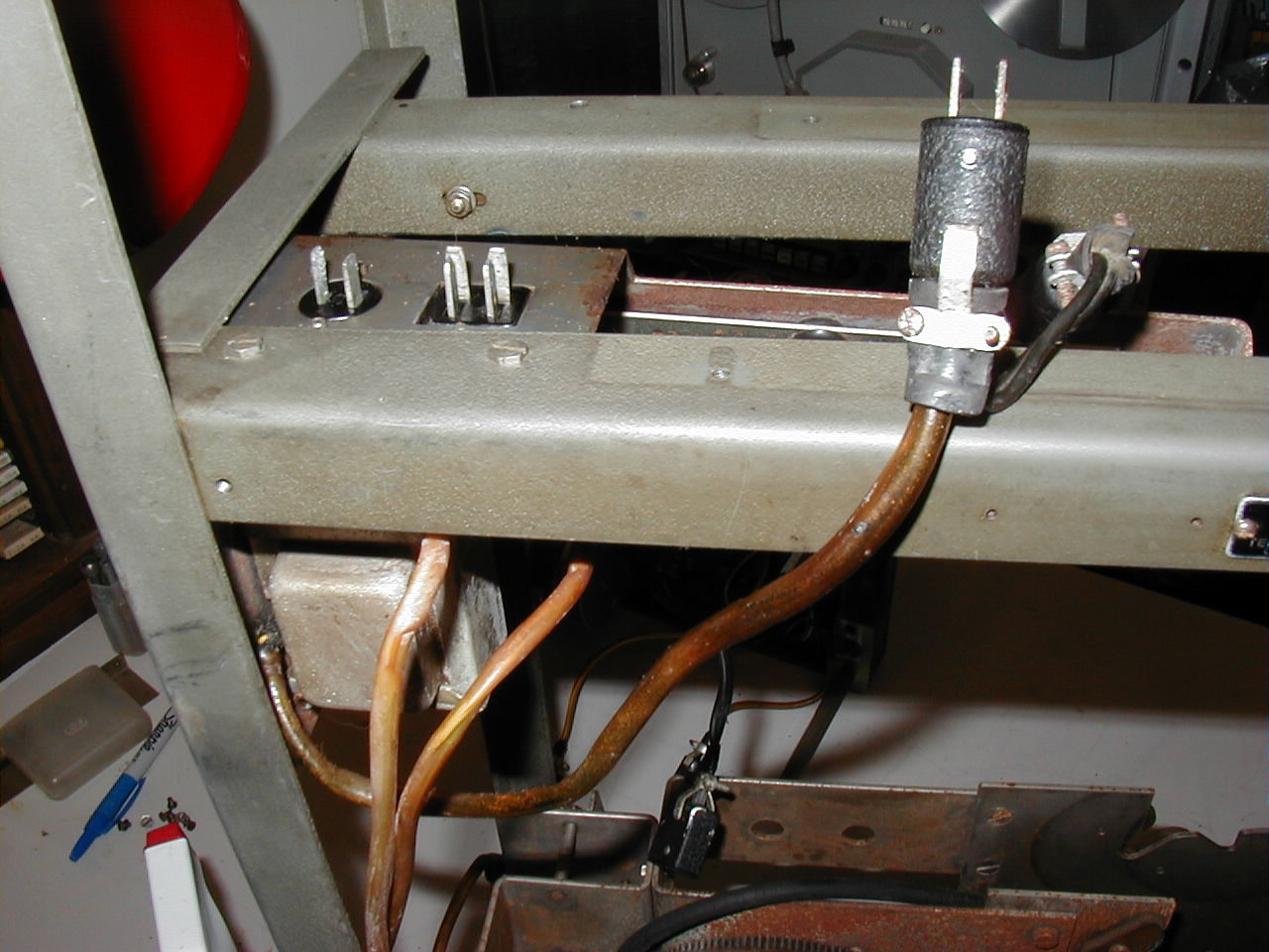 T T |
Connectors from top deck to base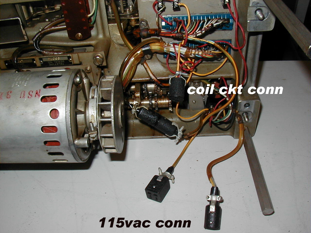 |
Top deck and base connected - oops I misaligned one plug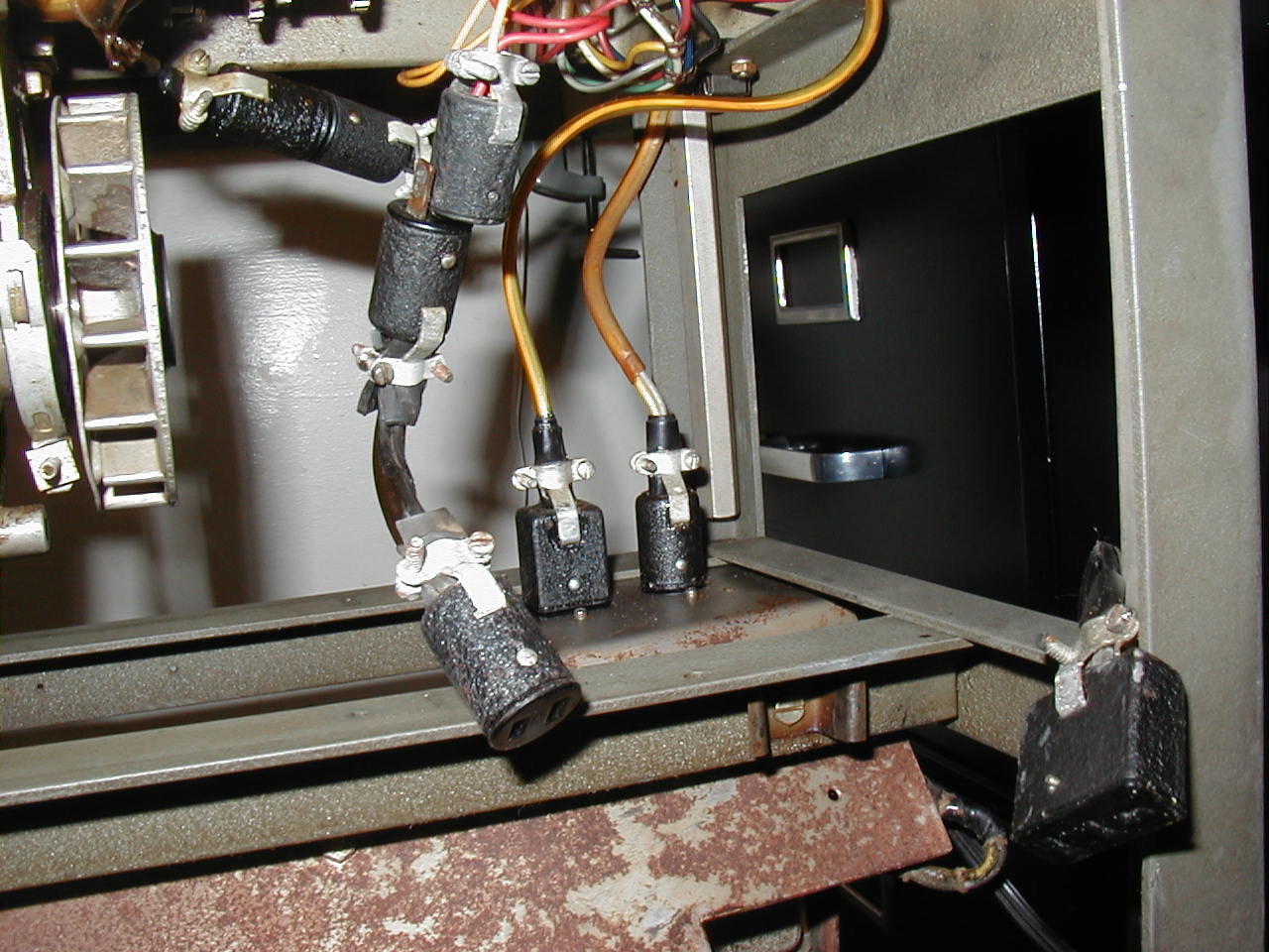 |
Two 15uf caps in base of unit - for power factor correction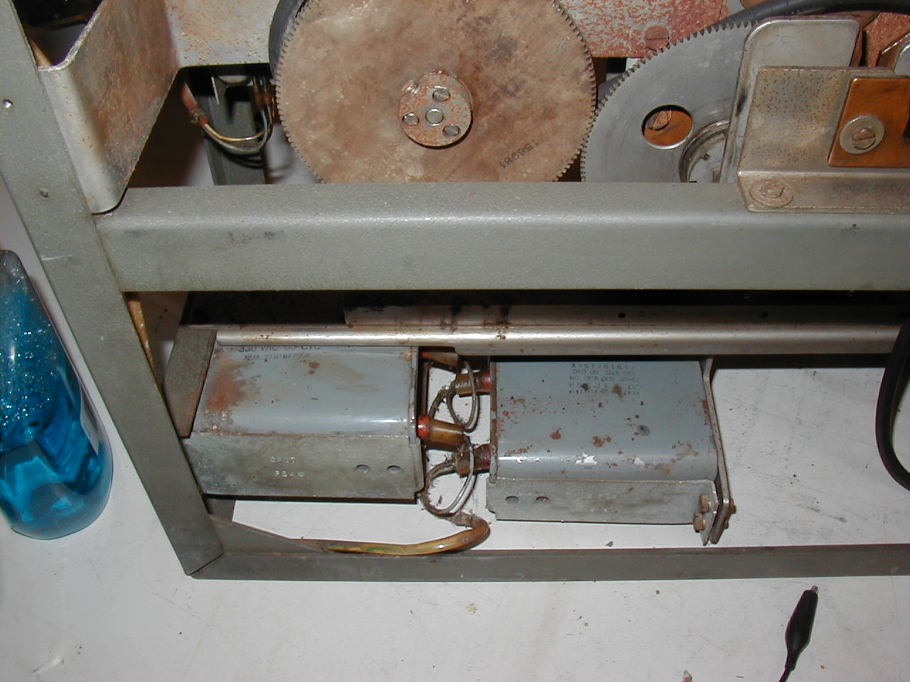 |
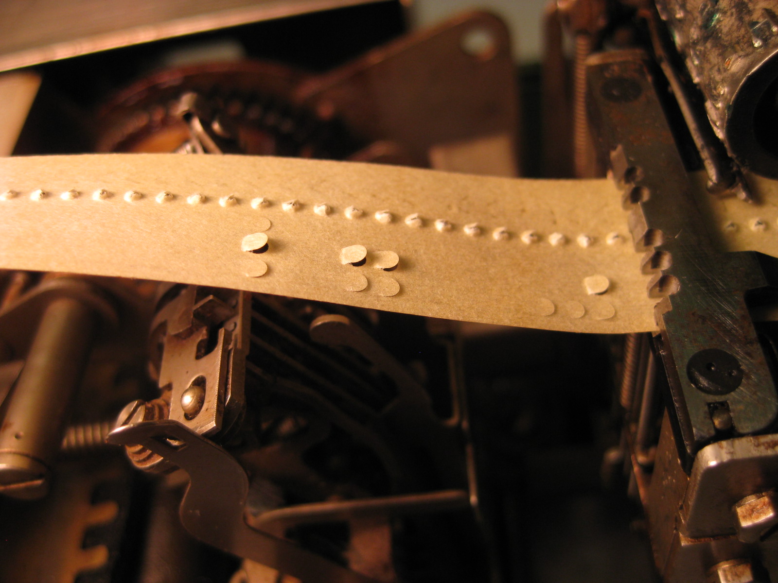 Holes 3 and 5 not punching properly |
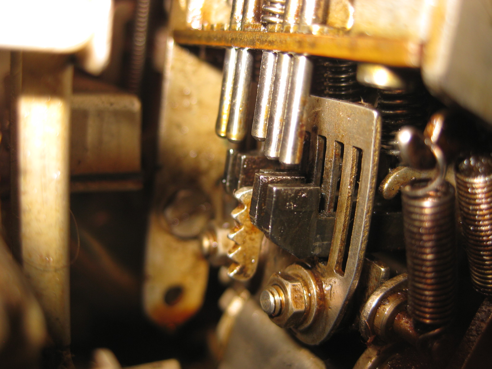 Punch pins 3 & 5 not being lifted far enough by punch slides |
 Punch pins 3 & 5 not being lifted far enough by punch slides |
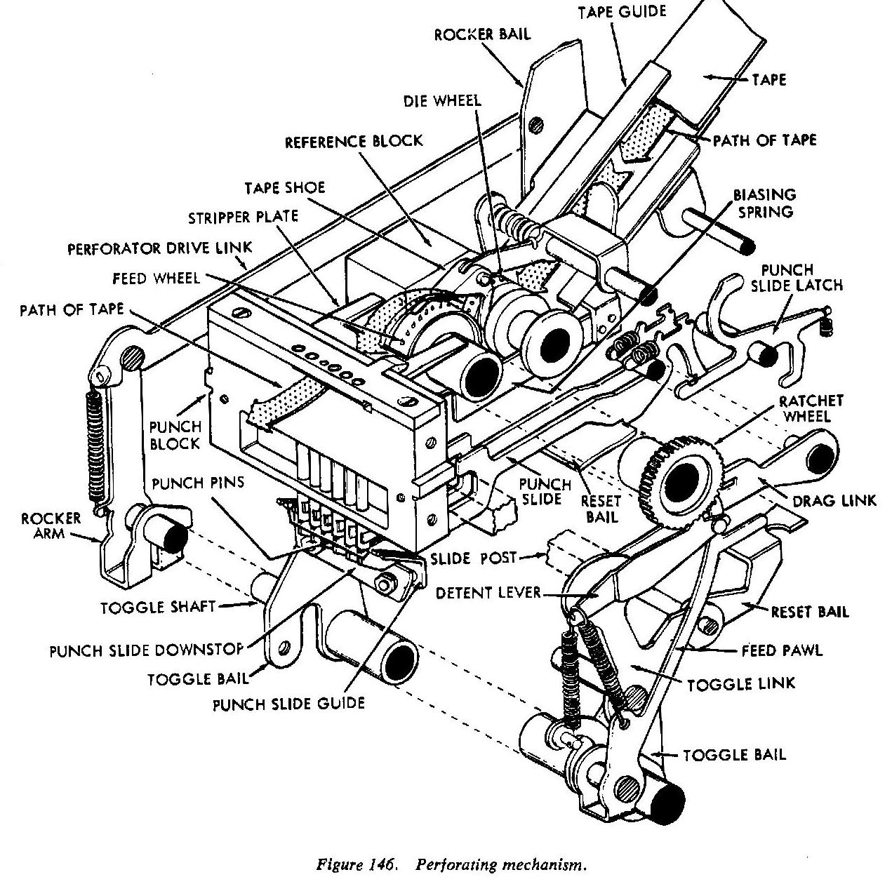 Punch mechanism |
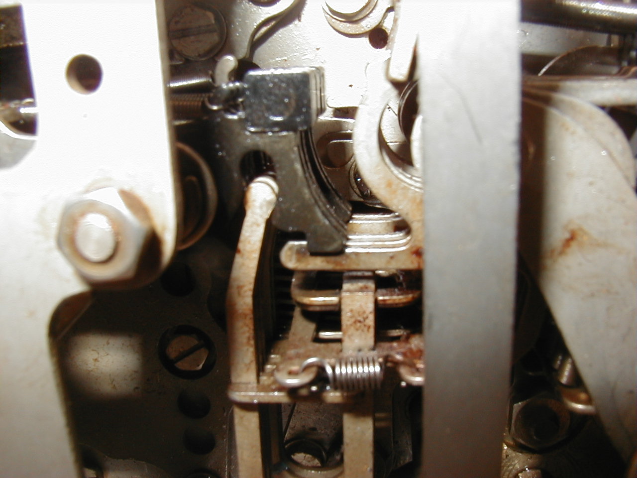 showing punch slide latches |
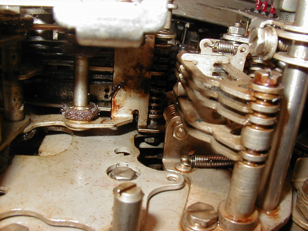 showing punch slide reset bail |
 Punch connector |
 After replacing worn punch slides 3 & 5 |
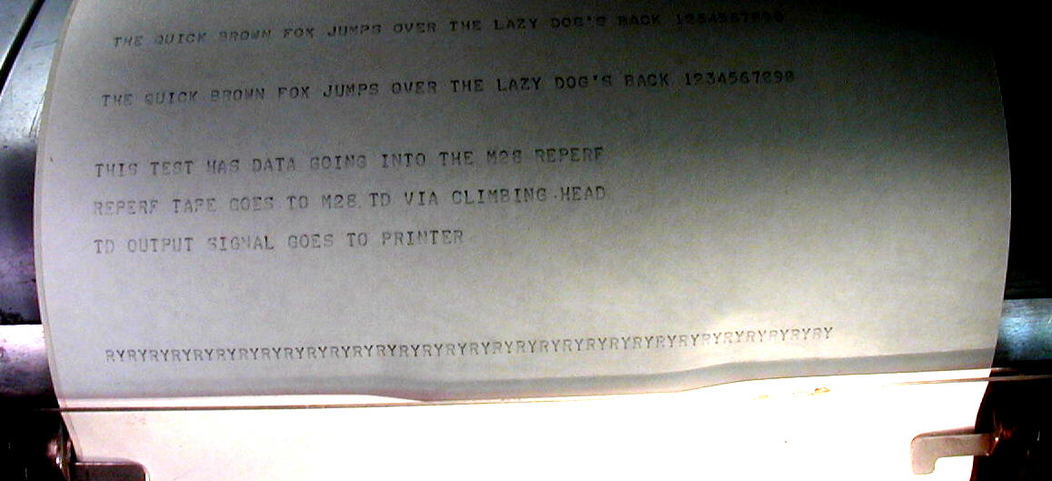
| TESTING 08/07/2010 - sent message from TU to 28RT (reperf-to-tape-TD) and then on to 28 page printer | |||
Robot 800 TU test message generator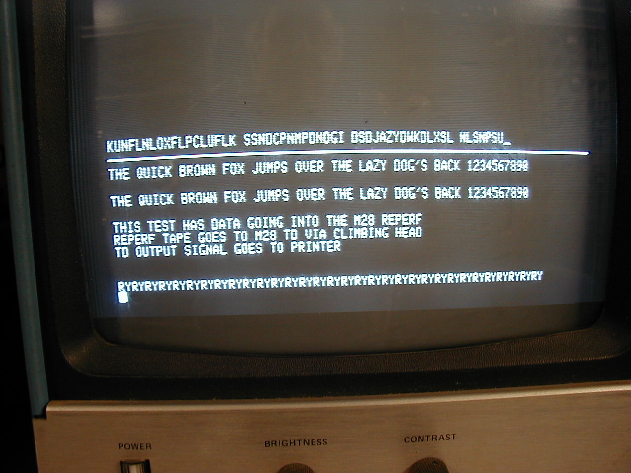 |
to 28RT reperf to tape loop to TD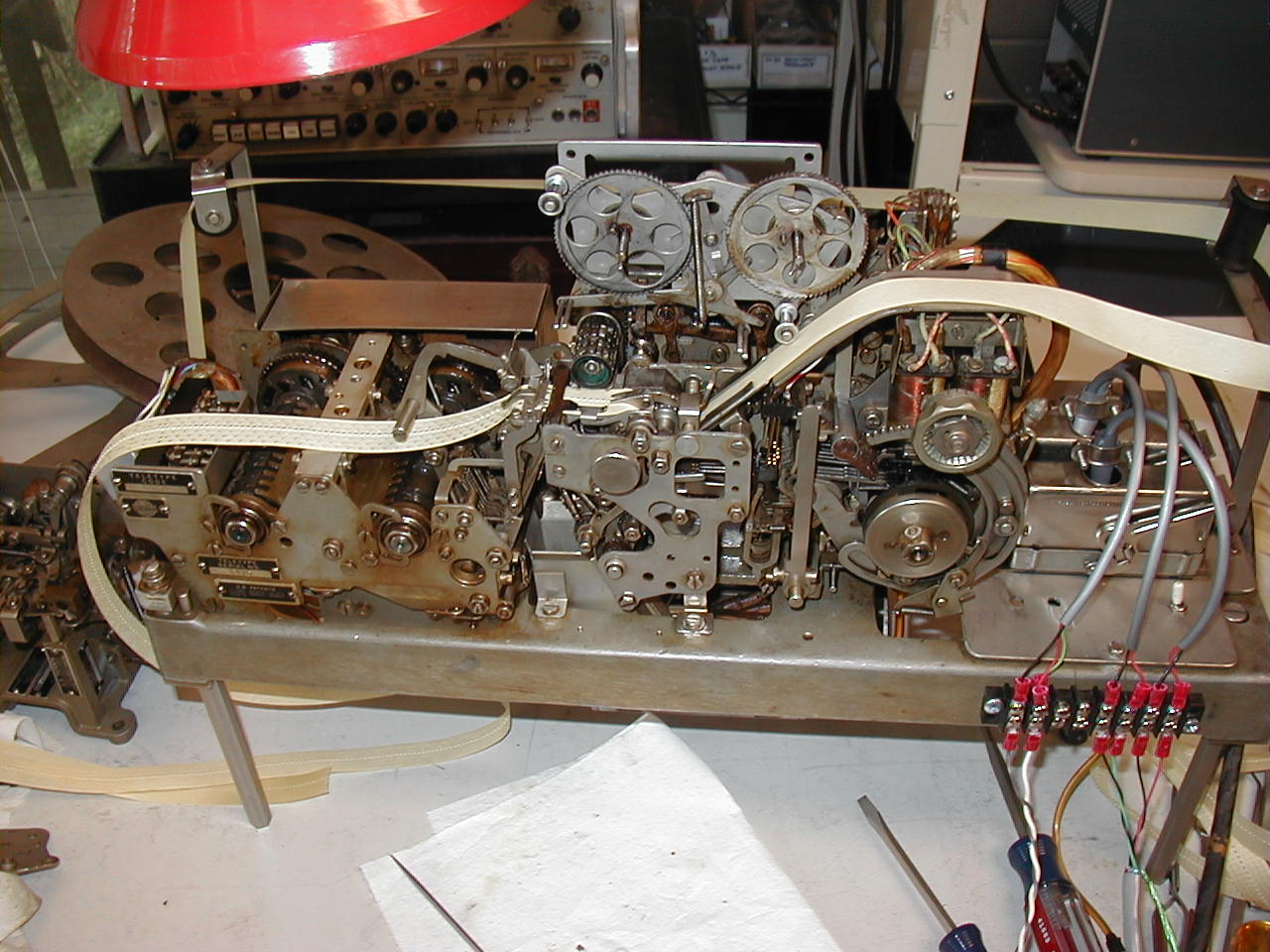 |
to 28KSR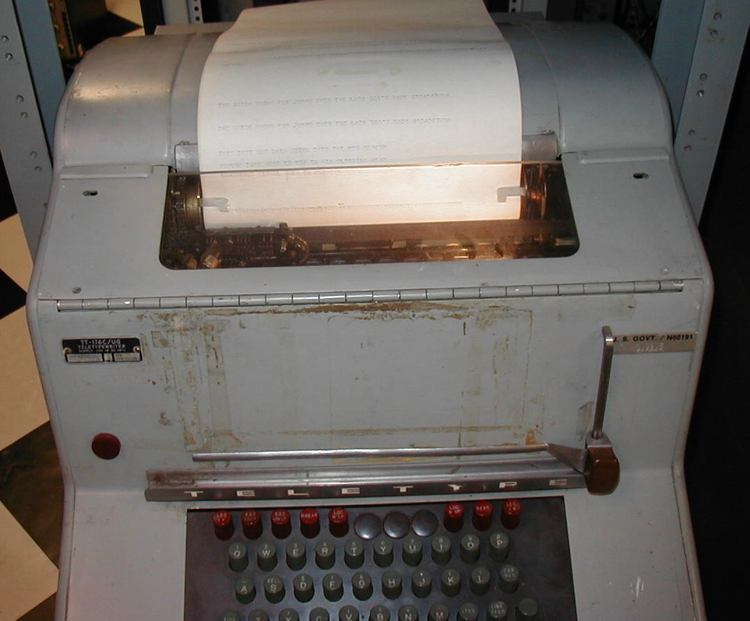 |
**** SUCCESS! *****
Video of my 28RT in operation
|