Just getting started - thanks to K4OZY, I have 100's of photos to scan.
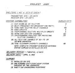
Project Judy Summary
April 1963 delivery date |
Receiver Site summary |
Transmitter Site summary |
--
|
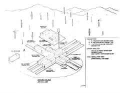
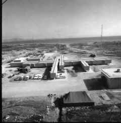
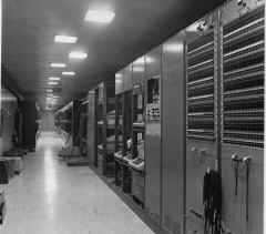
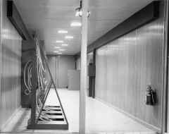
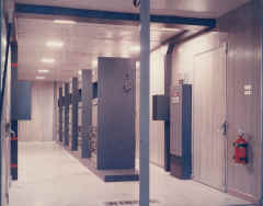
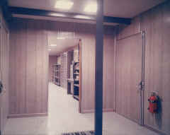
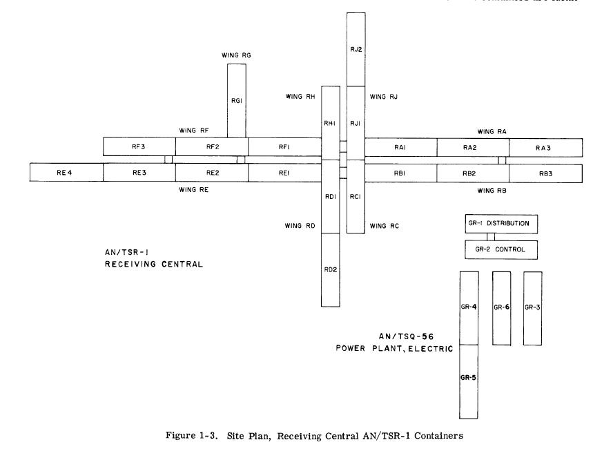
Receiver Site - Nea Makri Greece
Most of these photos were taken while the trailers were under
construction or as installed in 1963. There were changes later.
|
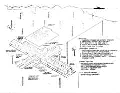
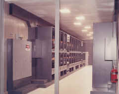
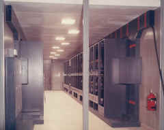
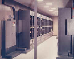
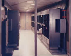
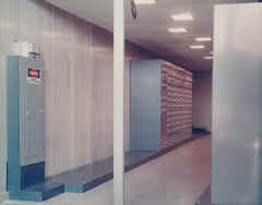
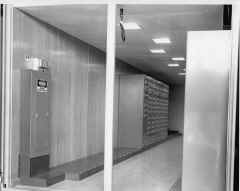
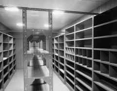
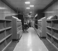
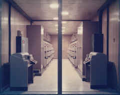
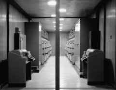
Receiver site
|
Site drawing after initial installation
RG1 is missing
|
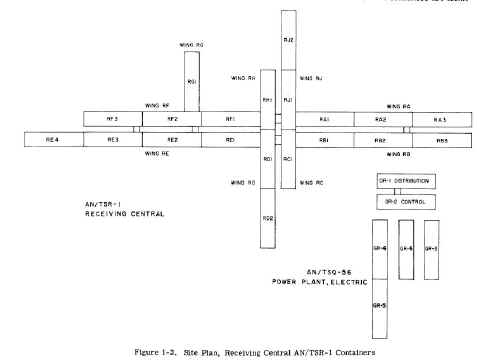 |
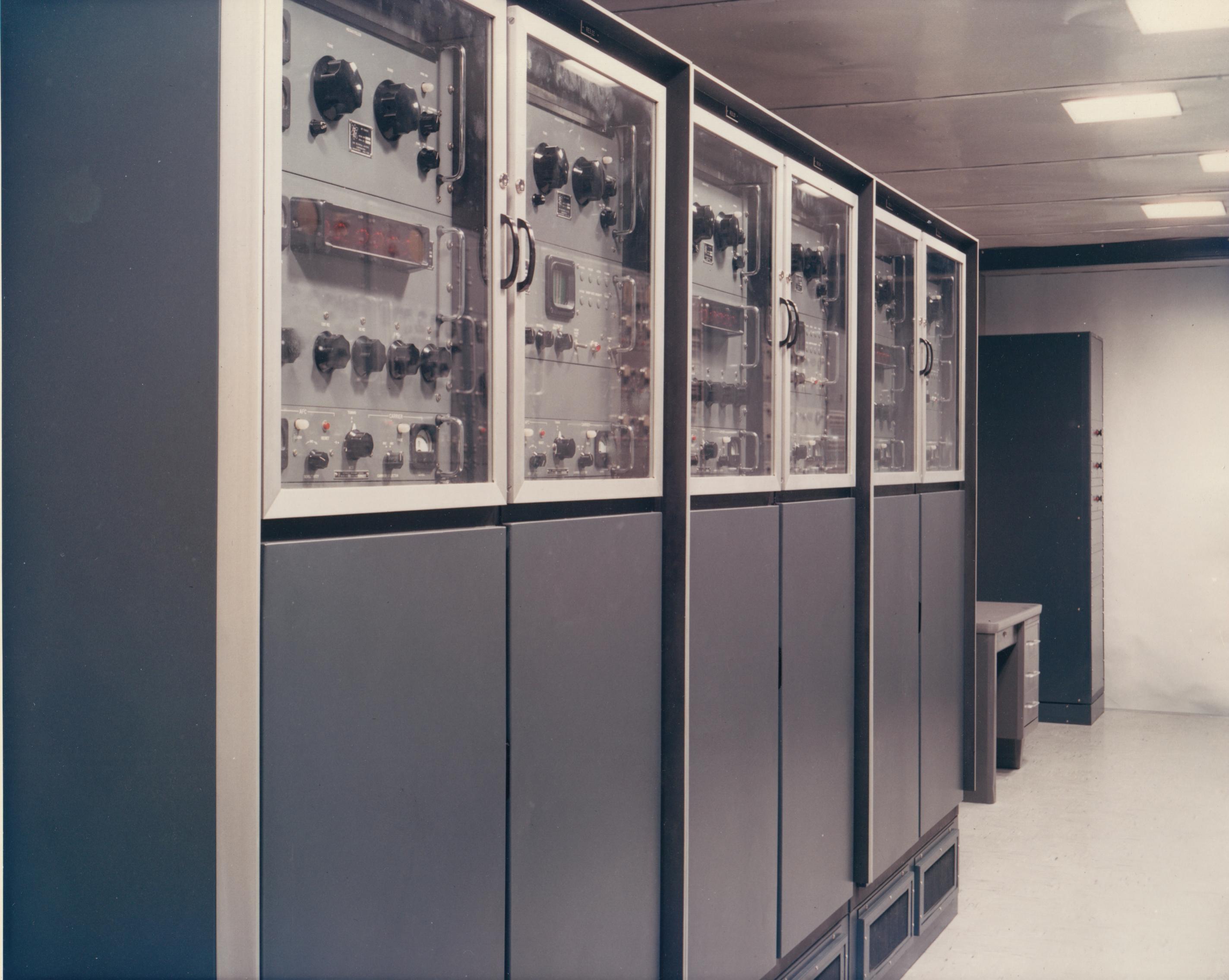
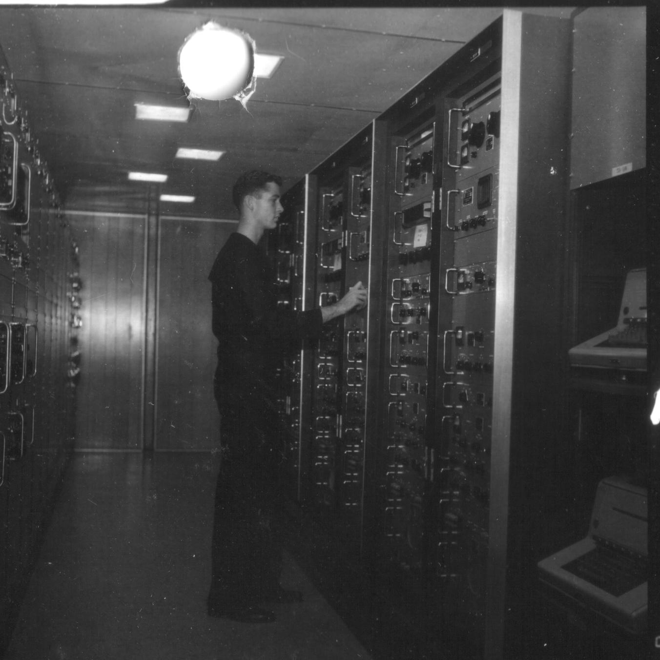
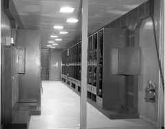
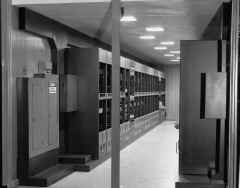
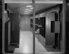
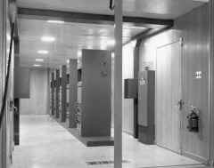
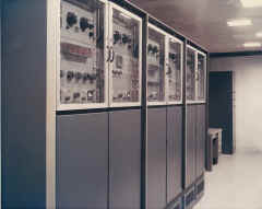
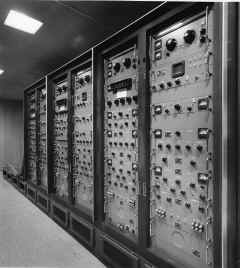
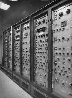
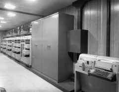
RA1 -HICOM/ASC
RA2 - Off-Line and Crypto Repair
RA3 - Not installed
RB1 - Classified Control
RB2 - Crypto
RB3 - Crypto |
RC1 - Multi-Channel Crypto
RD1 - Electronic Repair
RD2 - Supply Container
RE1 - Unclassified Control
RE2 - HICOM Voice & Microwave
RE3 - Receivers and RF Patching
RE4 - Not installed |
RF1 - Message Center
RF2 - C/W Ship/Shore
RF3 - Air/Ground
RG1 - Communication Office
RH1 - TTY Repair
RJ1 - NTX Receive
RJ2 - NTX Send |
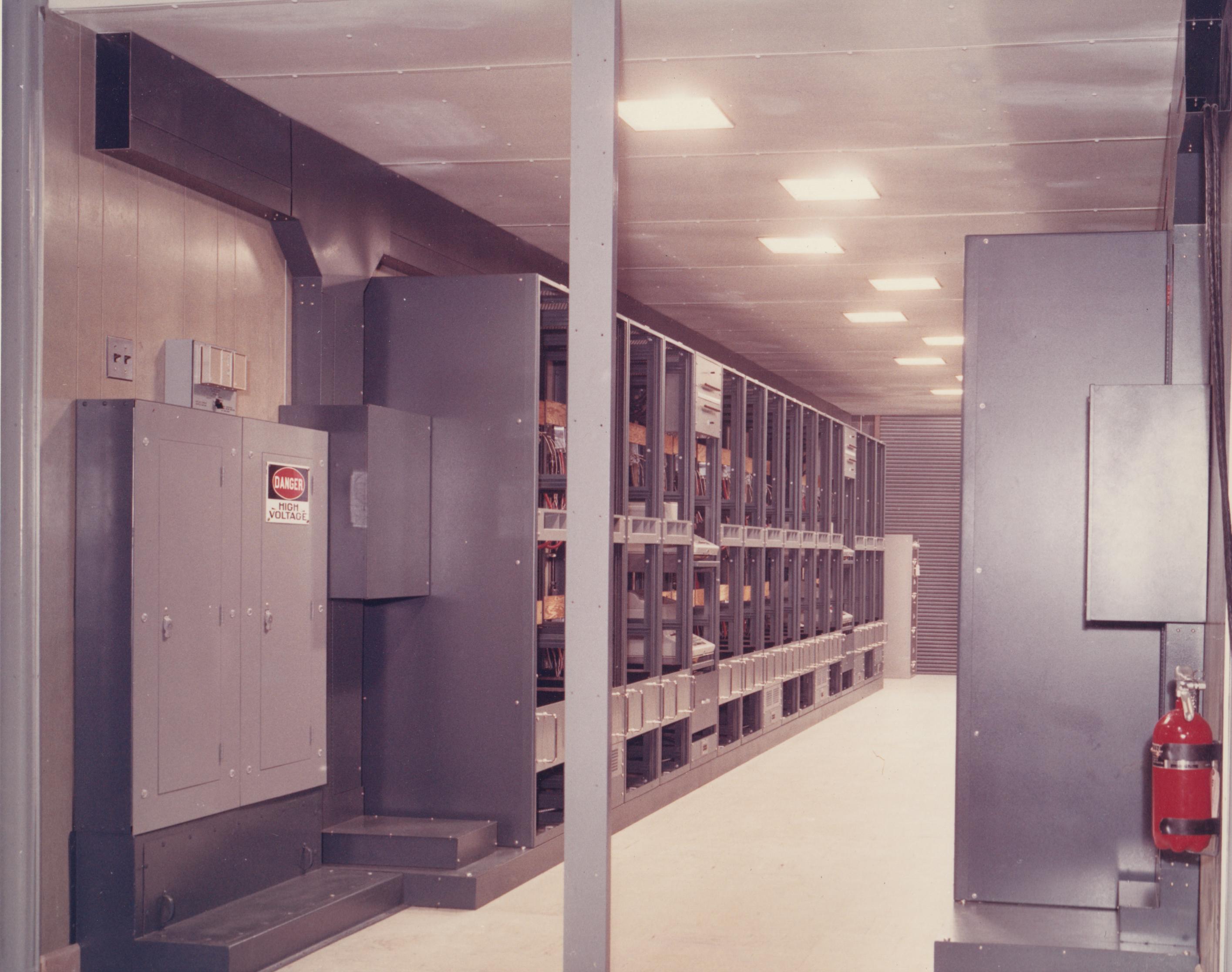
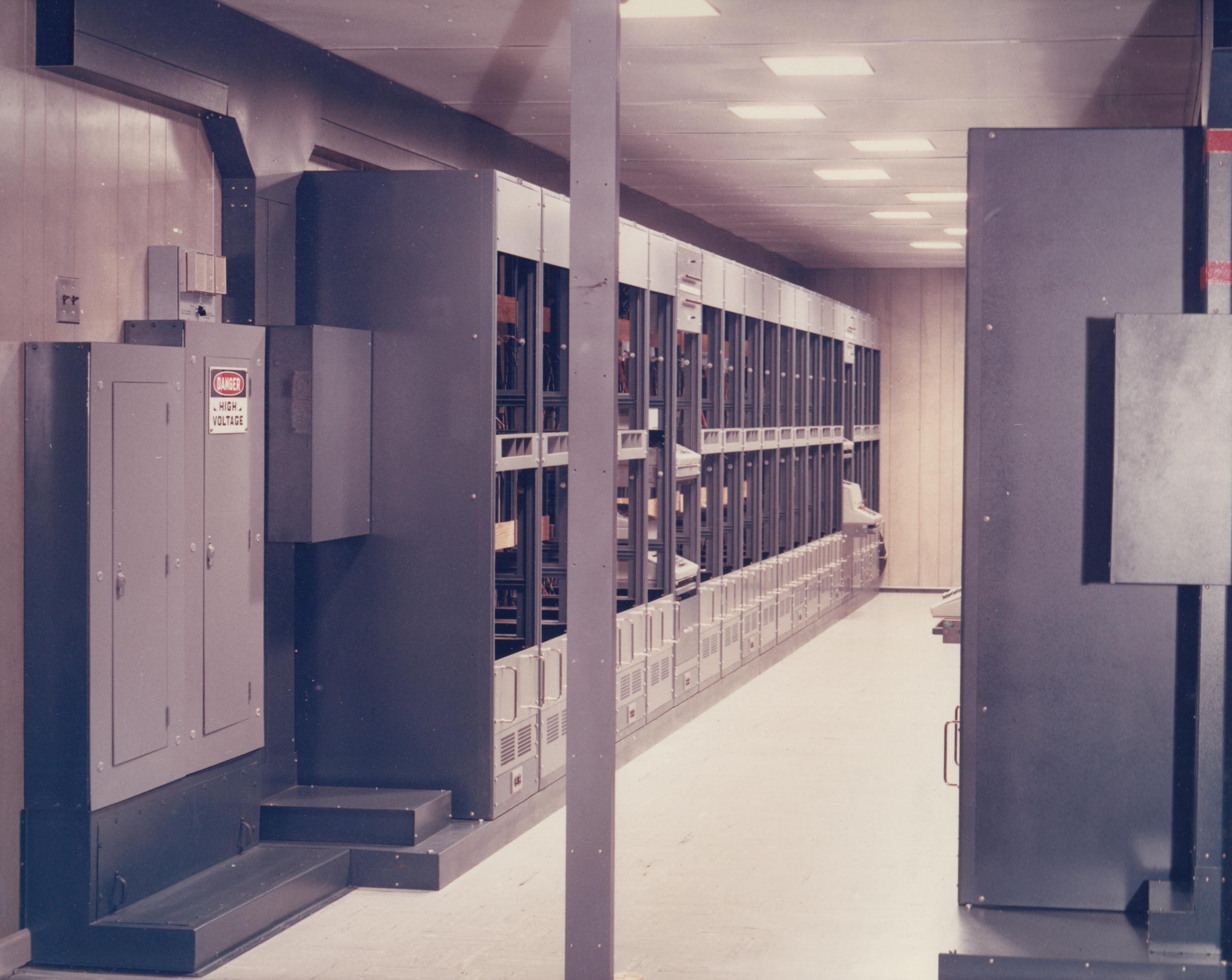
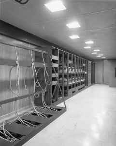
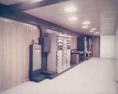
Electric Power System
GR1 - Power Distribution
GR2 -Power Control
GR3 and GR6- Generators
GR4 and GR5 -No Break Power
|
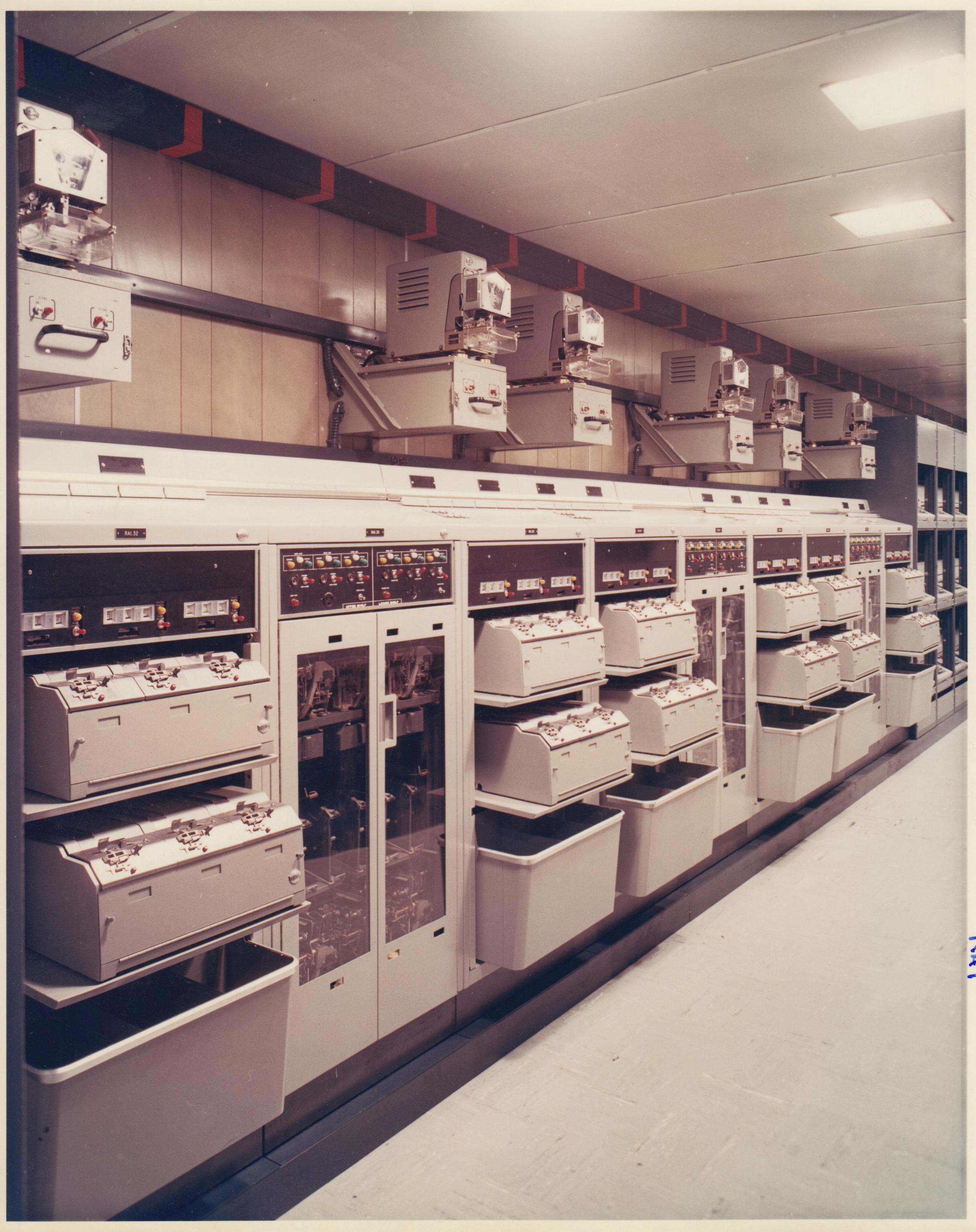
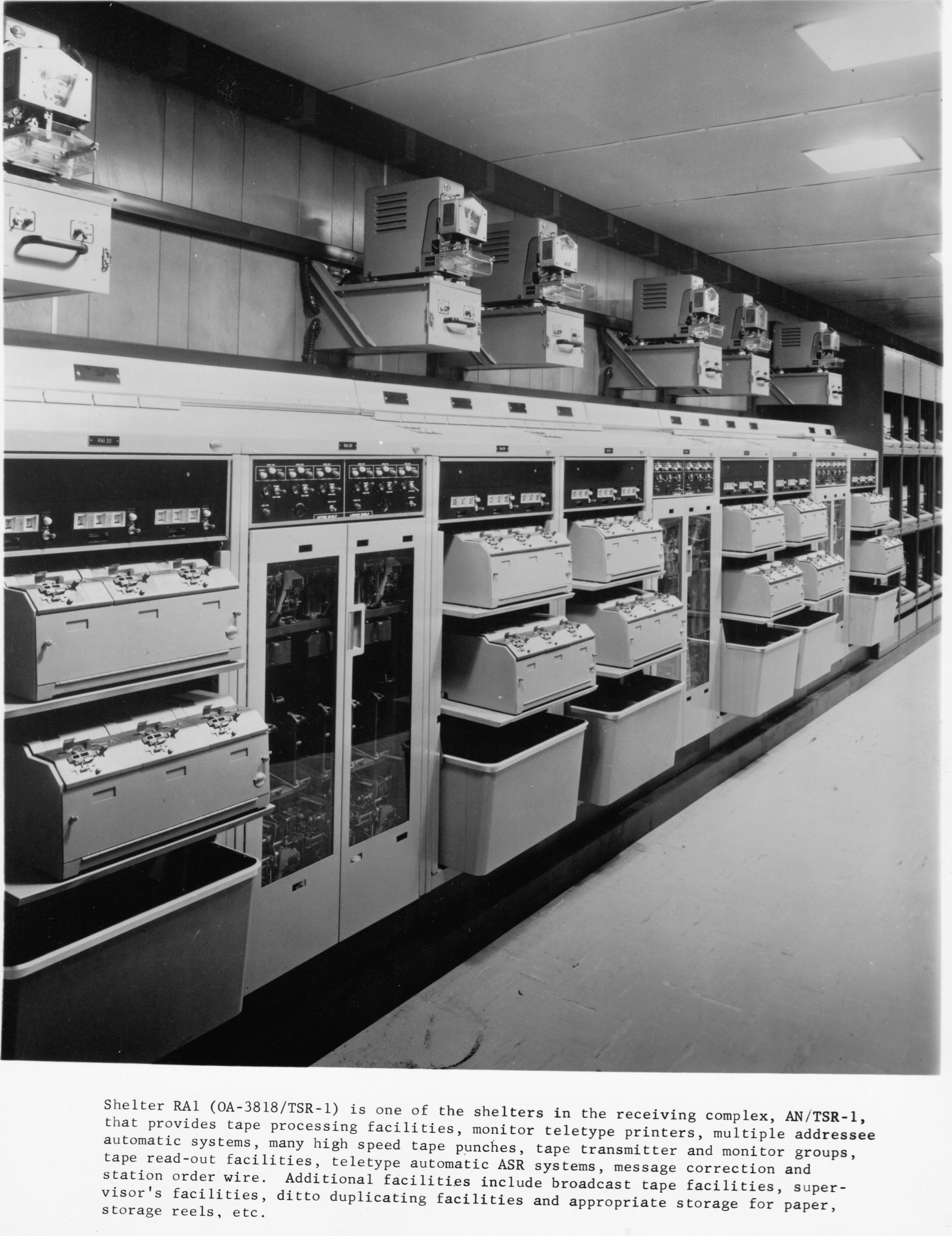
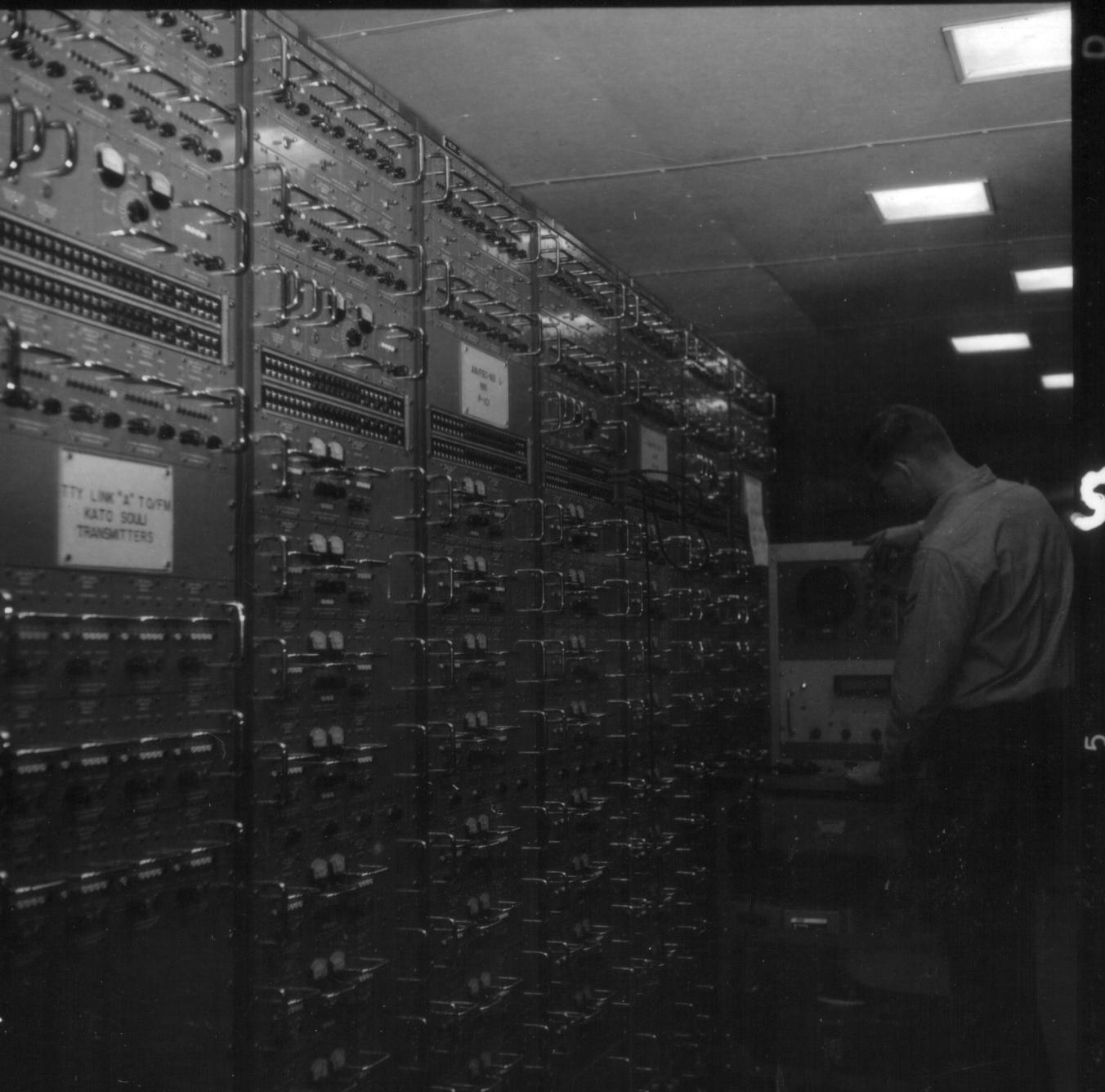
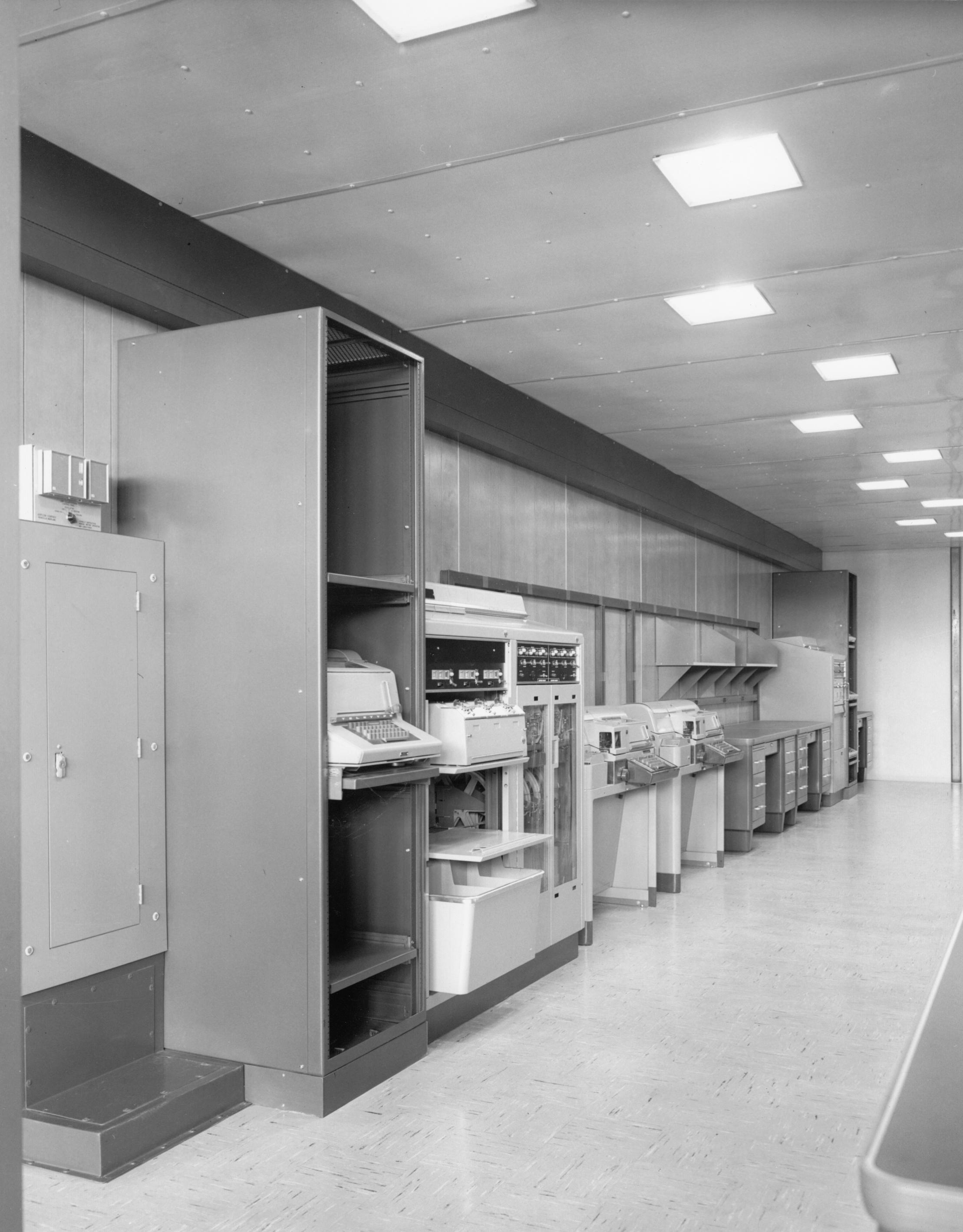
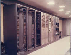
| RA1 HICOM/ASC - Provides 18-line HICOM/ASC torn-tape
relay facility with provision for 12 receive page-copy monitoring. Equipment
includes an AN/FGC-73 Multiple Address Processing System with console and
and eight TT-329 high-speed punches; an AN//FGC-59 torn-tape relay system
consisting of three TT-331 teletype receive groups, six TT-333 teletype
transmitter groups, three TT-232 transmit monitor groups, and 12 TT-176A
receive page copy monitors with an associated TTY monitor patch panel.
Additional teletype equipment include an AN/UGC-6 run-off position, an
AN/UGC-6 message correction position, and a TT-47 station order-wire.
Additional facilities include monitor reel and broadcast tape storage
cabinet, supervisor's desk, ditto machine, paper cutter, and a metal
storage cabinet. |
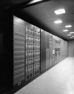
RA1 HICOM/ASC
|
RA1 HICOM/ASC during installation
 |
RA1 HICOM/ASC
 |
RA1 HICOM/ASC
 |
RA1 HICOM/ASC
 |
RA1 HICOM/ASC
 |
RA1 HICOM/ASC
 |
 |
|
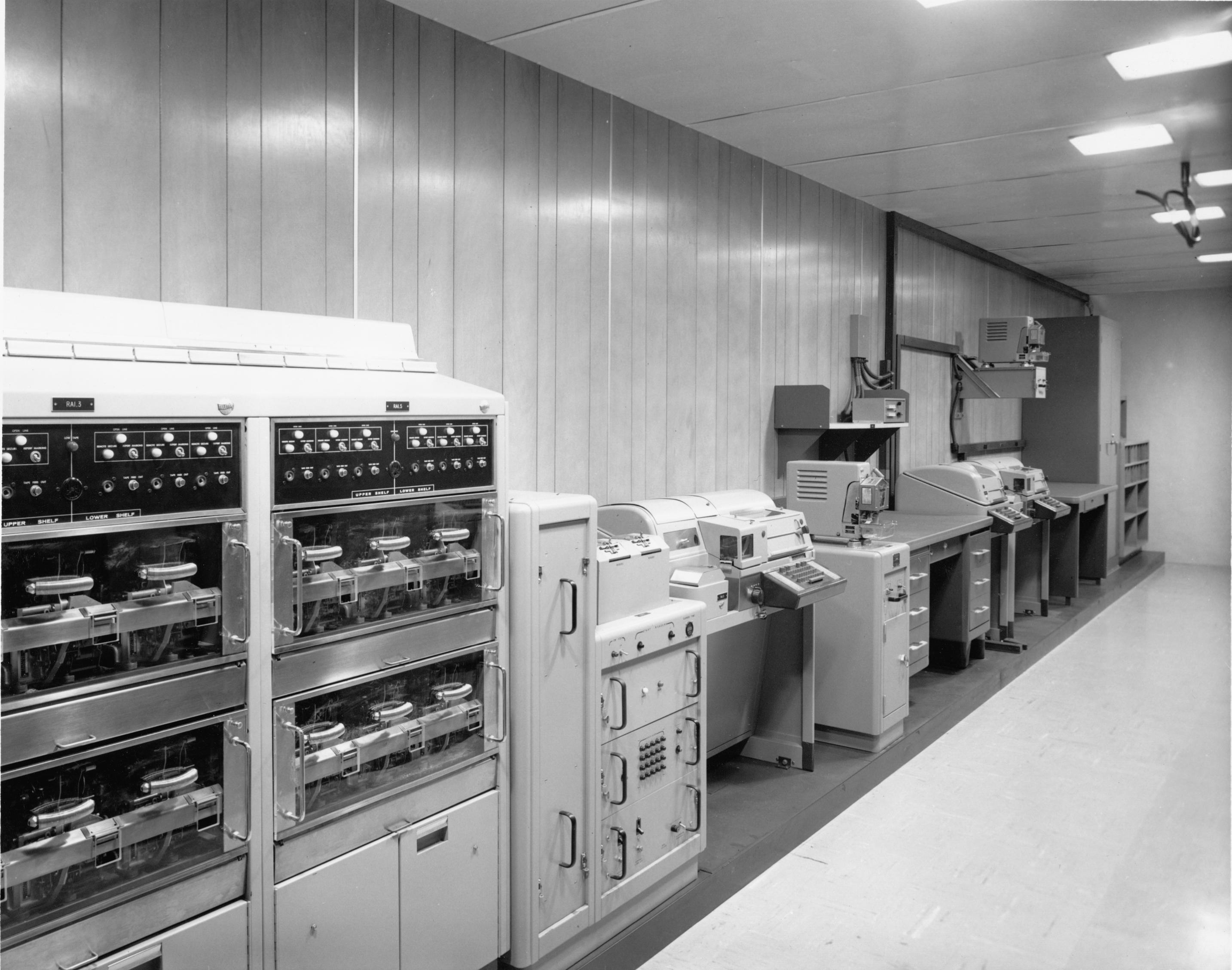
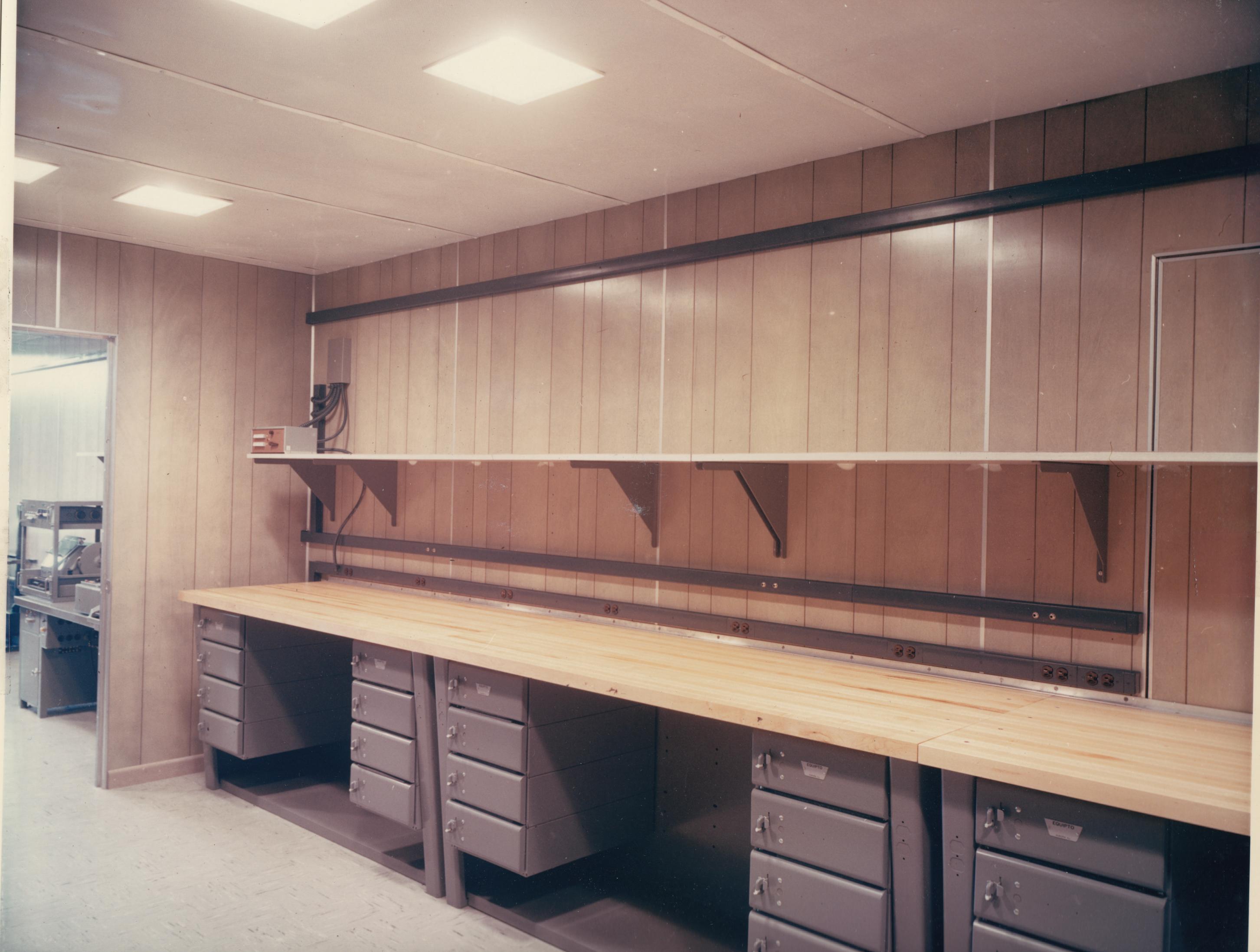
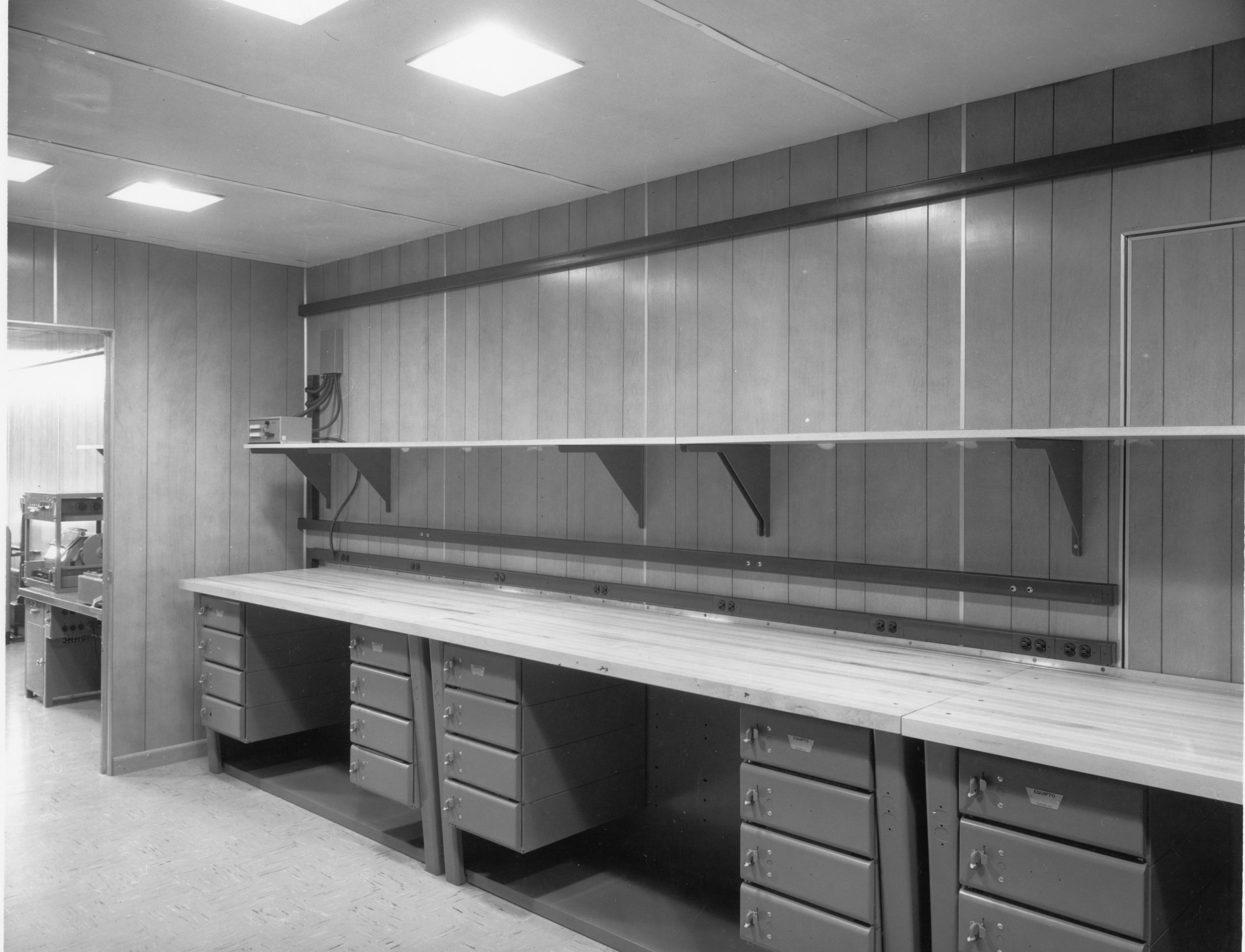
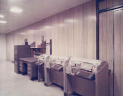
RA2 Offline & Crypto Repair - The Off-Line
area houses two AN/GGA-1 positions, two HW-19/10 positions, one AN/UGC-6 and two
TT-171A teletype units for use with the HW-19/10 equipment, one AN/UGC-6 and one TT- l7lA for use on pony circuits,
and a large floor-mounted safe for storage of classified material. The repair
area is equipped with workbenches, a utility shelf,
test equipment, test carts,
tools, and cabinets for storing parts and
equipment. Signal trunk lines are provided from the
workbenches to the RED MDF. A RED voice-intercommunication unit is installed on the utility shelf
above
the workbenches.
|
RA2 Offline Crypto
 |
RA2 Offline Crypto
 |
RA2 Crypto Repair
 |
RA2 Crypto Repair
 |
RA3 Special Receiver (NOTE - not installed at Nea Makri)
- Container RA3 is a special
equipment container designed to provide in itself a complete communication
facility dependent only upon a primary power source. Container RA3 can
operate at communication stations using 10-kc phase-shift signaling such
as a Receiving Central AN/TSR-1, or at those stations using standard 20-ma
or 60-maDC signaling. RA3 is configured for both RED and BLACK circuitry
and is equipped with completely separated RED and BLACK ferrous-shielded
ducting, audio and DC patching and programming facilities, and RED and
BLACK primary power distribution.
Equipment provided in container RA3 includes one RED and
one BLACK signal control rack (each with audio and DC capability), one
KW-26C rack, two AN/UGC-6 send positions, two TT-171A receive positions,
one TT-47 order-wire position, an RF distribution rack housing two
SPP-40416 RF patch panels and three CU-656 multicouplers, twenty-one
pieces of special test equipment, and provisions for mounting three
special receiver racks and one special test rack. Additional facilities
include a safe for storage of classified material, a file safe, two file
cabinets, one desk, two equipment storage cabinets, three spare-parts
storage racks, and one workbench. The container is equipped with a baffled
entrance door at the rear and an emergency exit door at the front end.
|
|
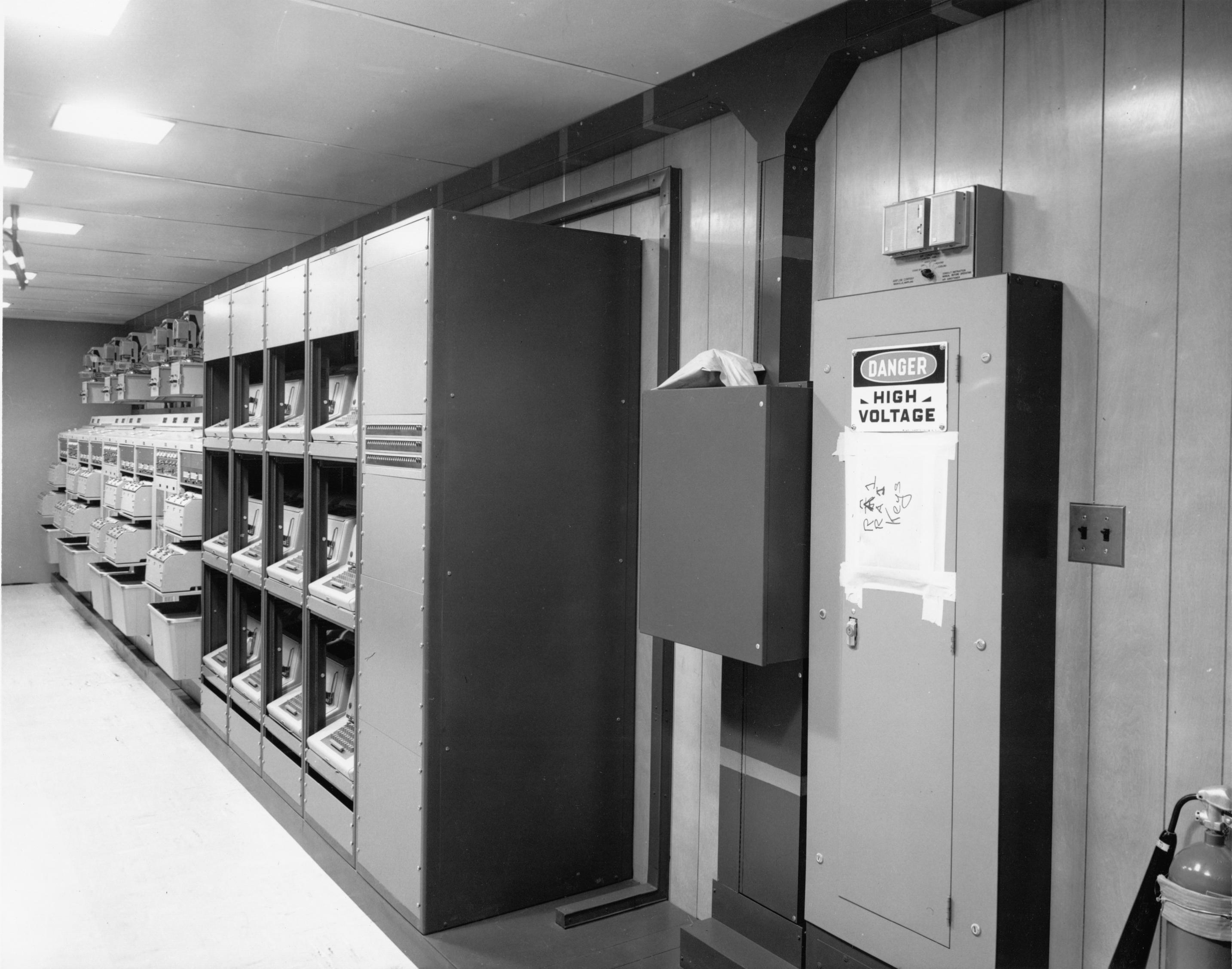
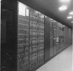
RB1 Classified Control - RBI contains the RED
Main Distribution Frame (MDF) and associated patchboard, four KW-37
positions, six point-to-point order-wire TTY's, four monitor TTY' s, one
station order-wire TTY, one KW-37 order-wire TTY, a AN/GGM-1 distortion
measuring set, a "Fox" 20-channel distribution amplifier, a tone
converter rack, a desk, a file safe, RED and BLACK INTERCOM units, and
provisions for installing four KG-14 units. |
RB1 - Classified Control
 |
RB1 - Classified Control
KW-37 equip not installed yet
 |
RB1 - Red Patch & MDF
 |
RB1 - Red MDF
 |
RB1 - Red Patch & MDF
 |
RB1 during installation
 |
RB1 - Red MDF
 |
RB1 - Red MDF
 |
 |
 |
-- |
-- |
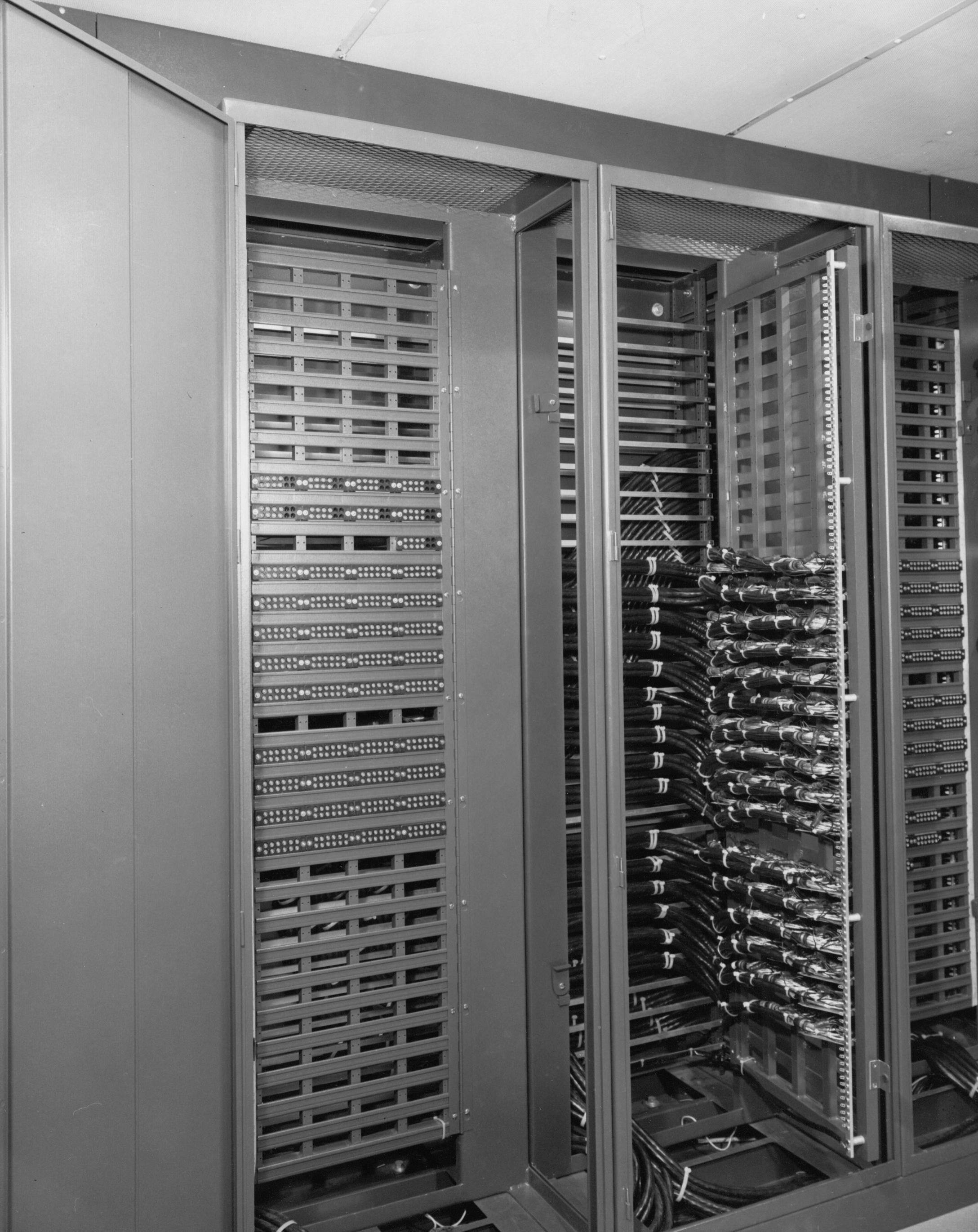
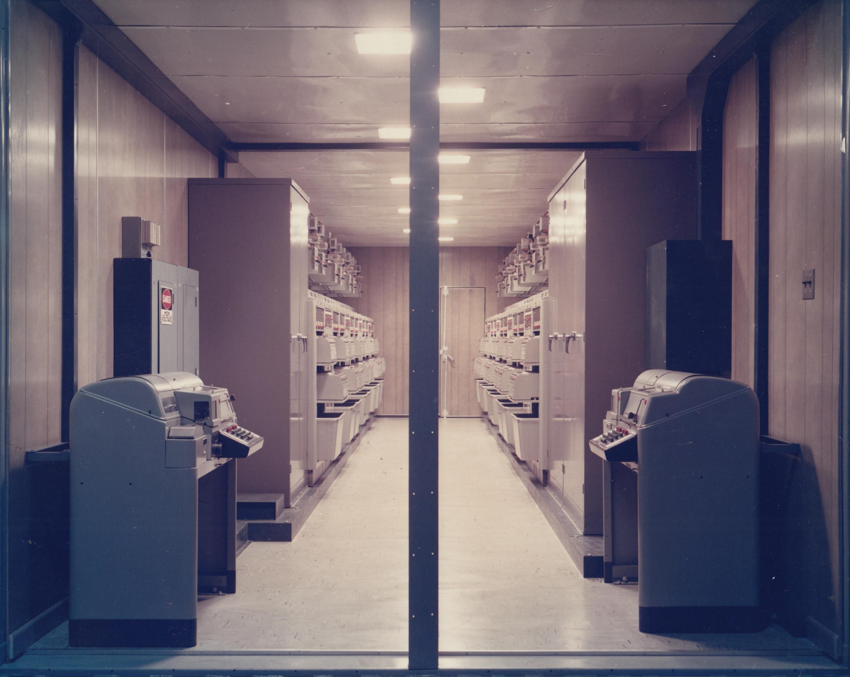
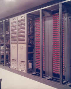
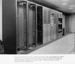
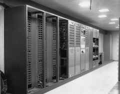
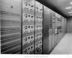
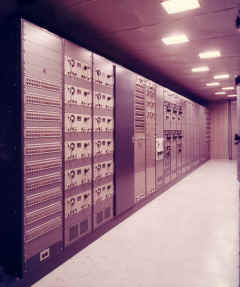
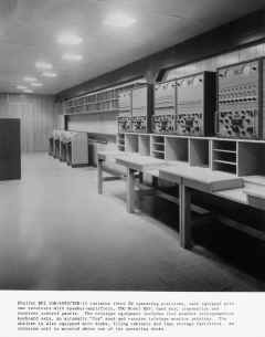
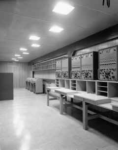
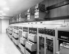
RB2 & RB3 On-Line Crypto - Container RB2 is a
part of the single-channel On-Line cryptographic area which consists of
containers RB2 and RB3. Container RB2 houses twenty-eight KW-26 operating
positions and associated order-wire equipment. Facilities provided in each
operating position include a tone converter drawer, a card holder, and all
hardware and wiring required for the installation of a send/receive KW-26
unit. Order-wire equipment includes eight full-duplex TT-176A teletype
units and four control panels. Additional facilities provided in RB2
include a RED INTERCOM unit, a desk, a file safe, a file cabinet, and one
equipment rack for future installation of KW-7 units.
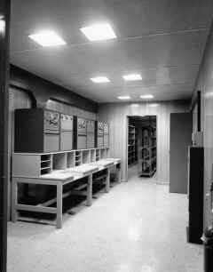
Container RB3 houses thirty-five KW-26 operating
positions, eight TT-176A order-wire teletype units and four order-wire
control panels. The KW-26 operating positions are identical to those
installed in RB2. A dual-readout digital clock is provided at the
front end of the container. |
RB2 Crypto
 |
RB2- note marked red signal wire ducts
 |
RB3 Crypto
 |
RB3 - note marked red signal wire ducts
 |
 |
 |
 |
 |
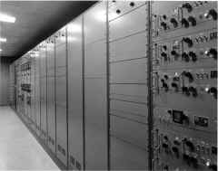
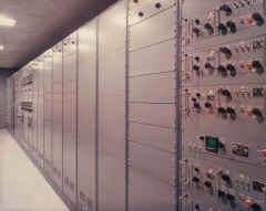
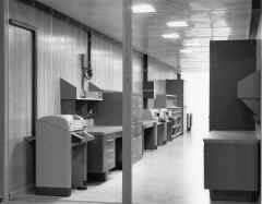
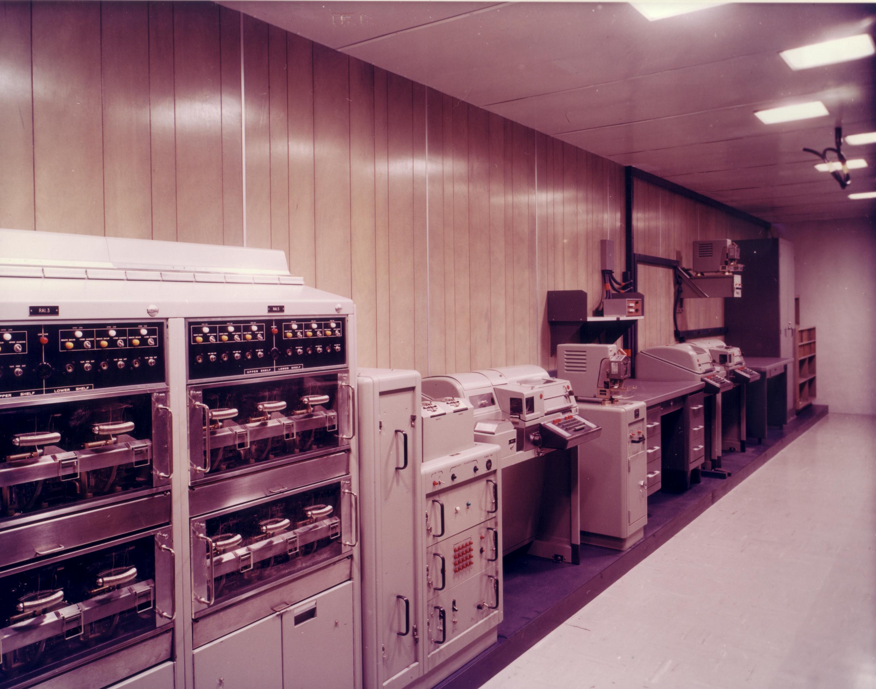
| RC1 - Multi- Channel Crypto - Container RC1 is the
multi-channel On-Line area providing five 4-channel cryptographic
operating positions. Each position is equipped with a send/receive
AN/UGC-1A multiplex terminal, tone converters, loop supplies, a TT-176A
order-wire teletype unit, and all hardware and wiring required for the
installation of a send/receive KW-22 unit. Additional facilities provided
include a RED INTERCOM, dual readout digital clock, a supervisor's desk
and a file safe. |
 |
RC1 - Multi-Channel Crypto
 |
RC1 - Multi-Channel Crypto
 |
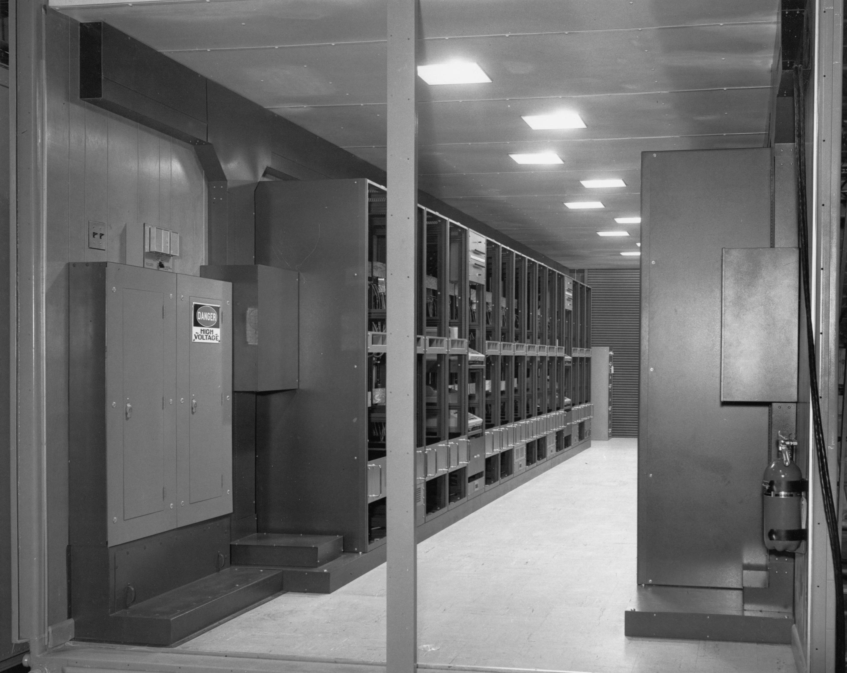
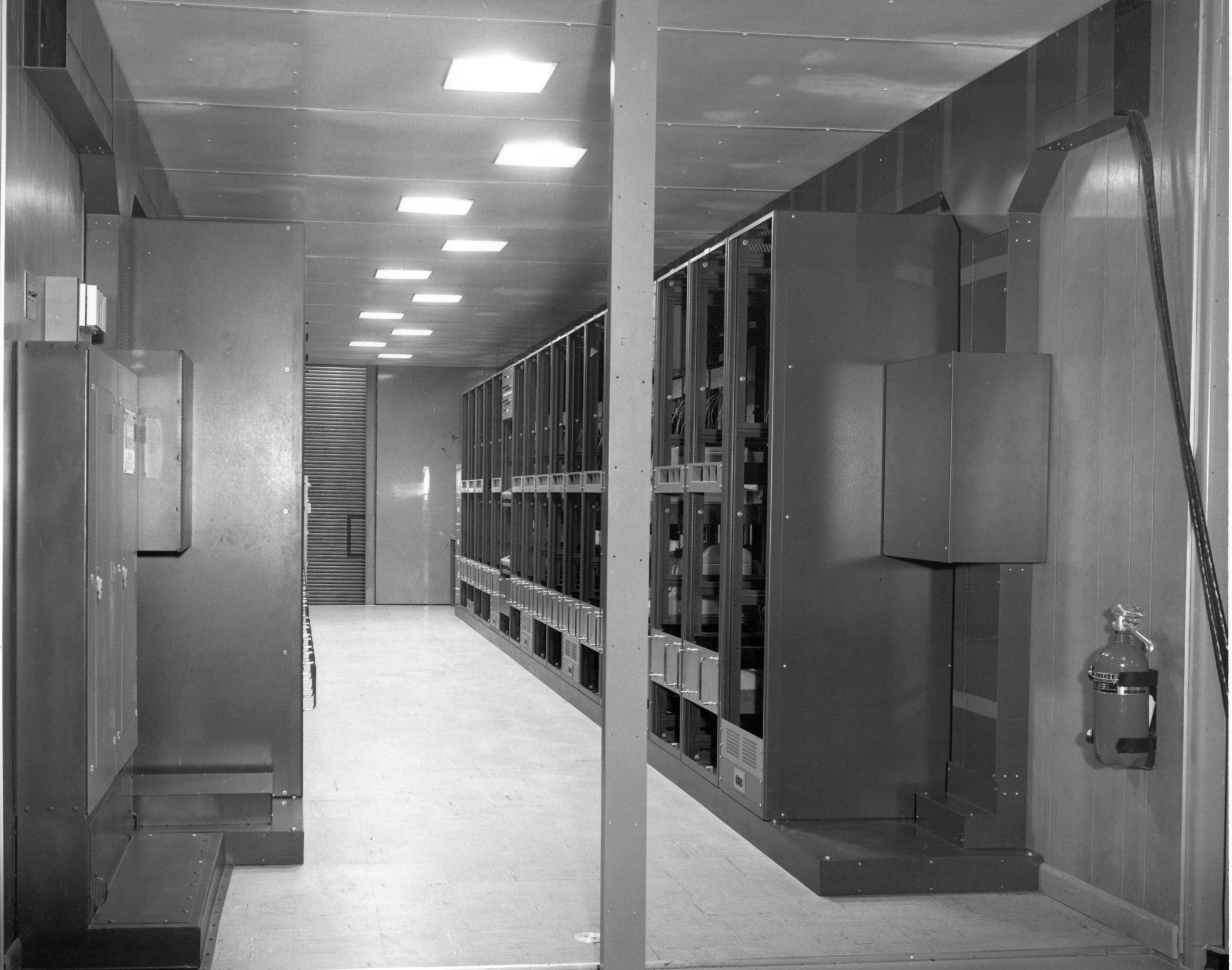
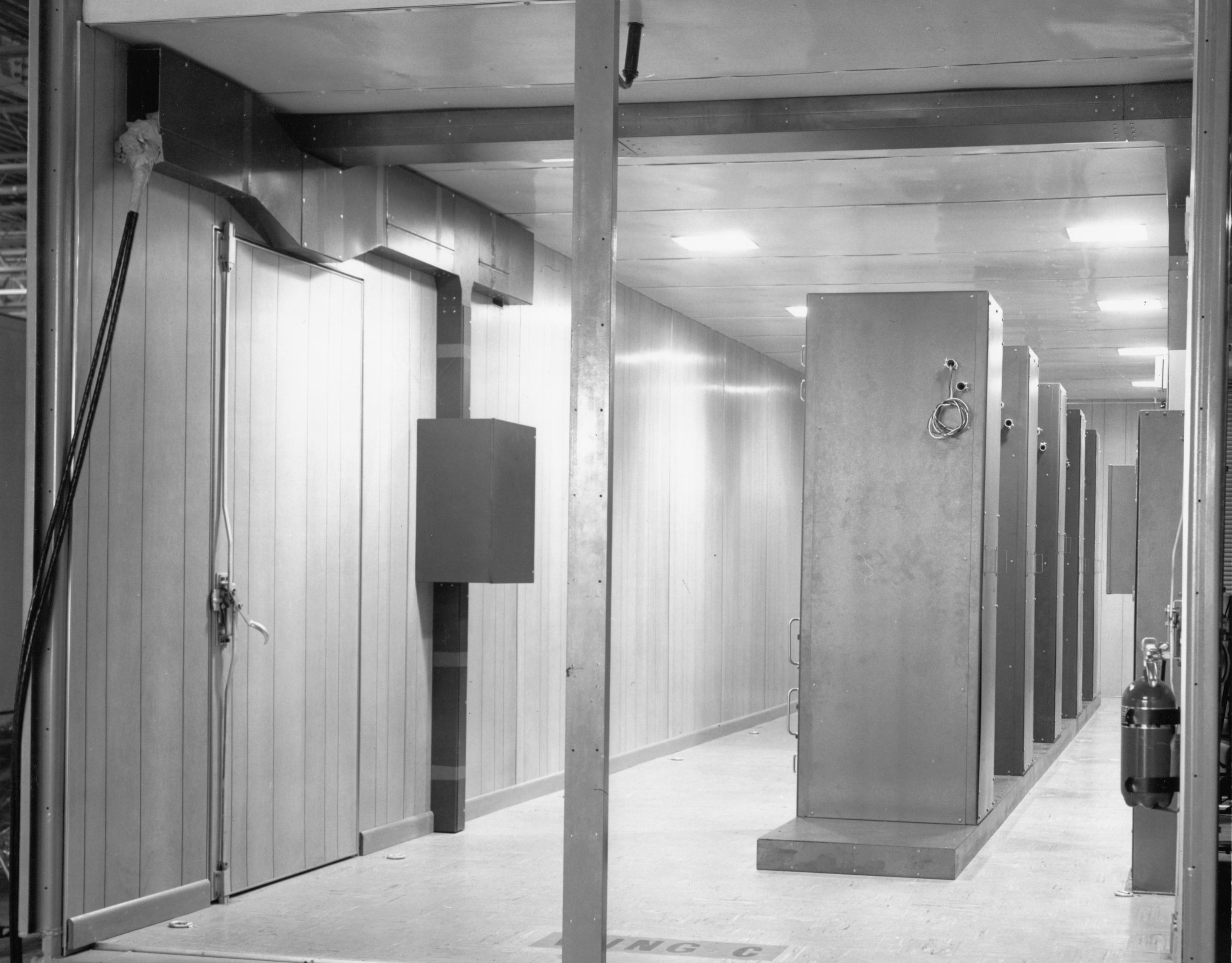
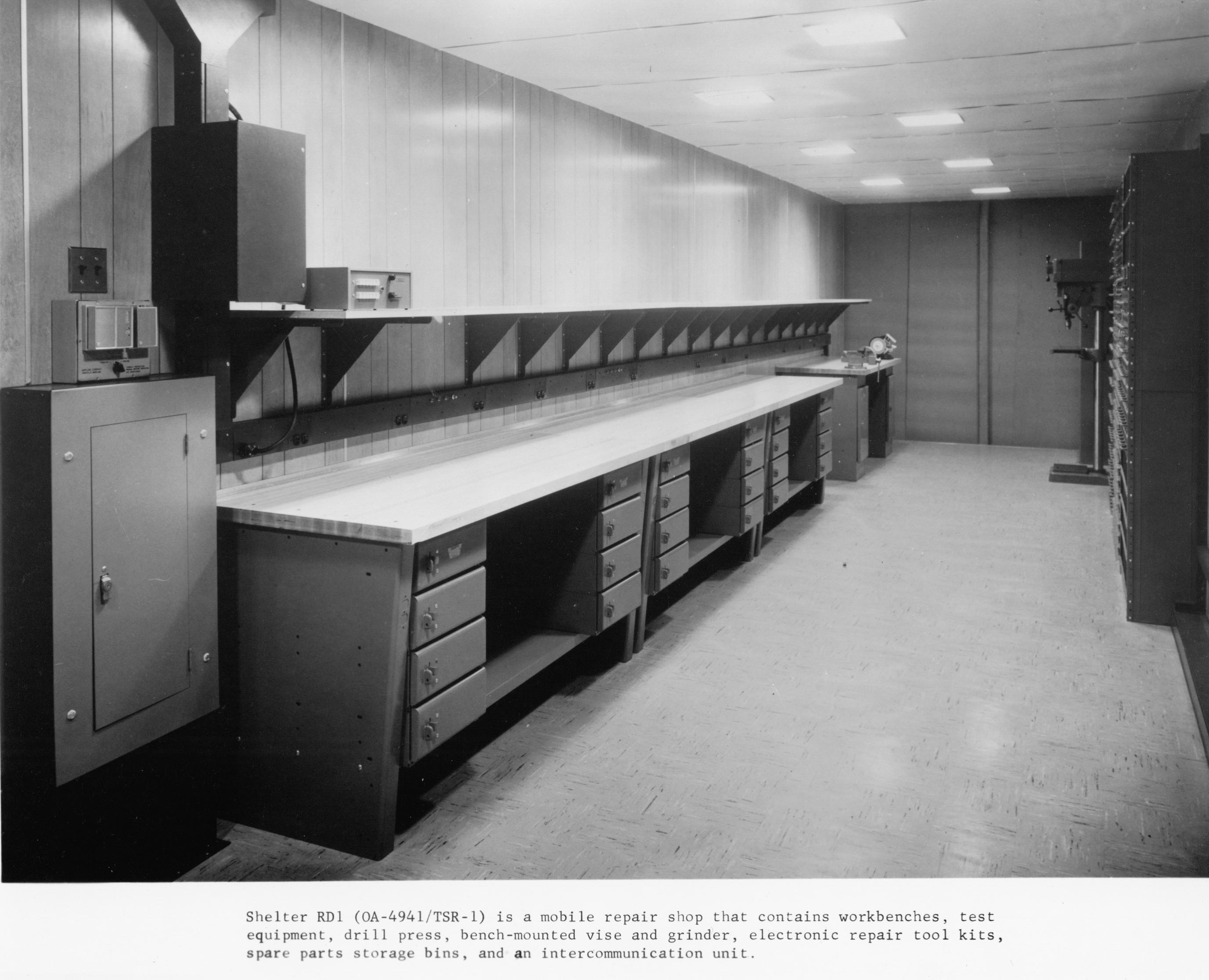
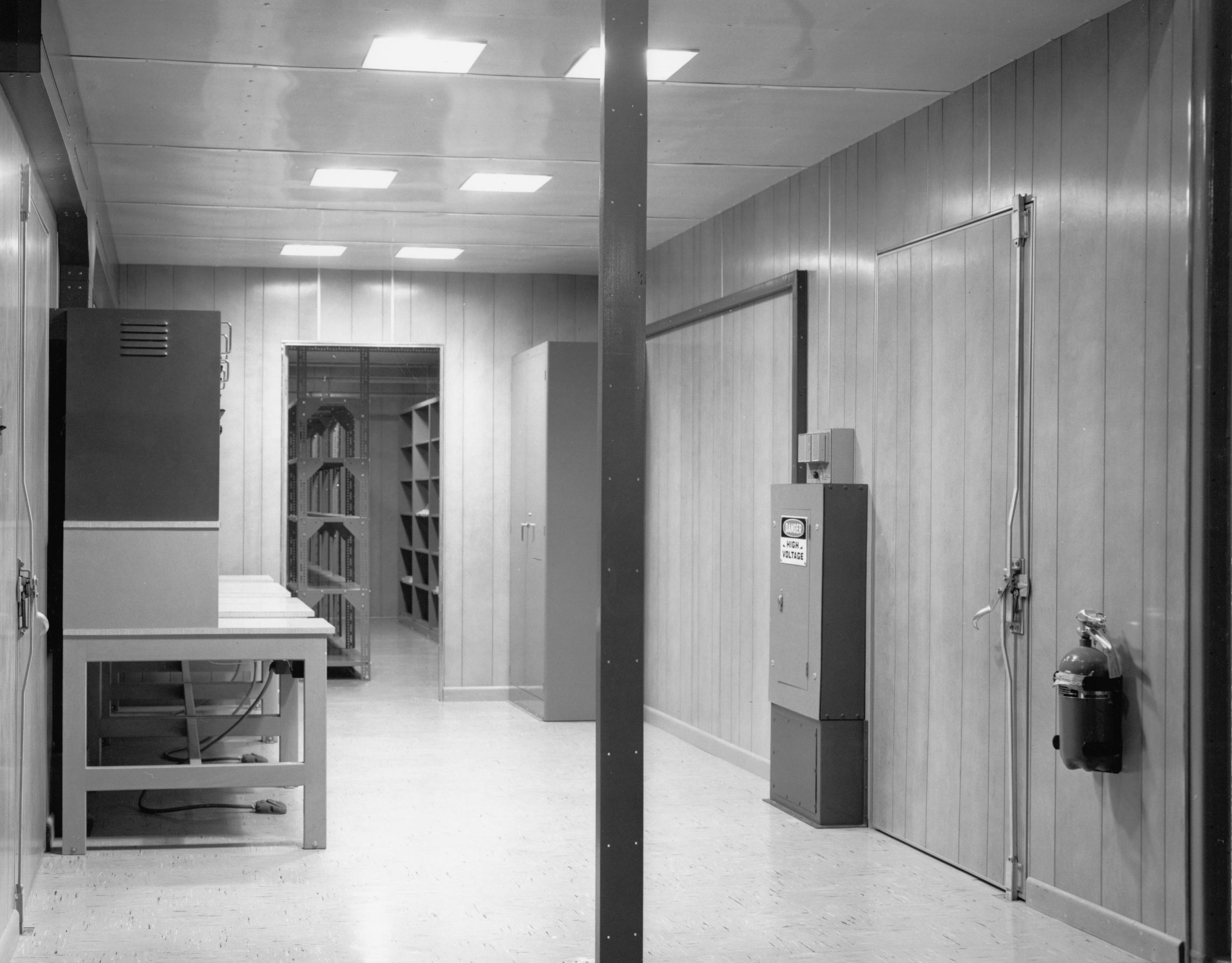
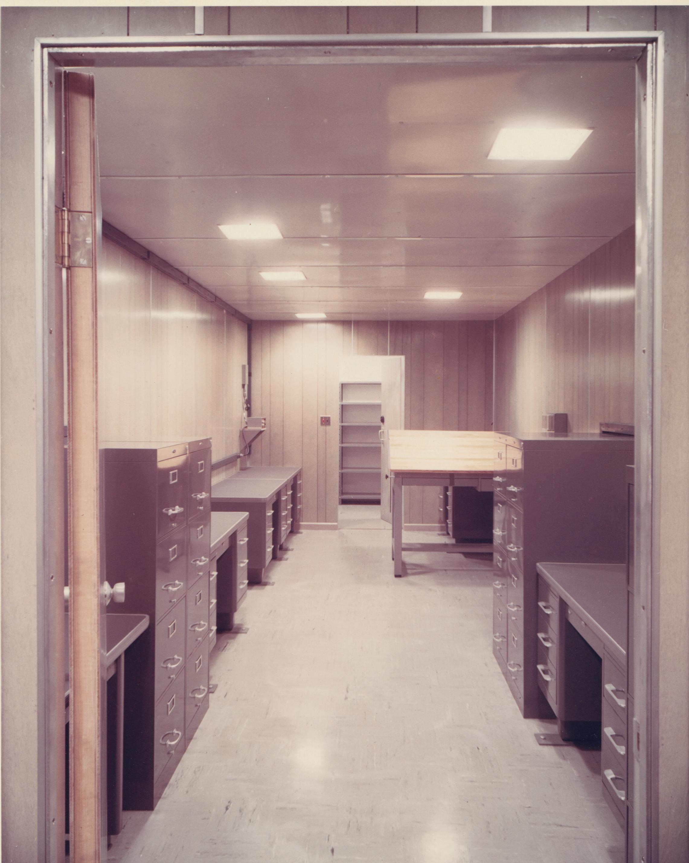
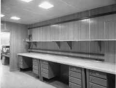
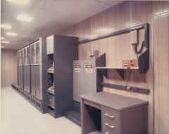
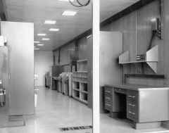
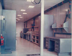
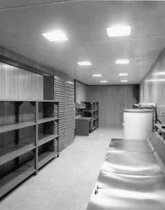
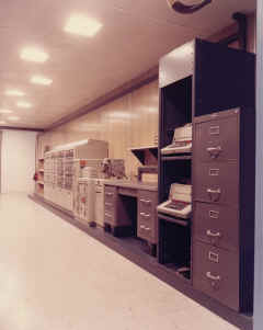
RD1 - Electronic Repair & RD2 Supply Container - Container RD1 is
the electronic repair shop of the Receiving Central. Equipment installed
in RD1 includes workbenches, parts storage bins, equipment storage
cabinet, drill press, bench-mounted vise and grinder, and a BLACK
INTERCOM. Three electronic repair tool kits, four mobile service carts and
twenty-one types of electronic test equipment are provided in this
container.
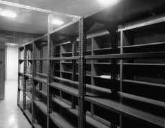
Container RD2 is the supply area of the Receiving Central.
A Dutch door equipped with a shelf for issuing supplies is located in the
rear wall and a door for loading supplies into RD2 is at the front of the
container. Supply facilities provided in RD2 include storage bins along
both sidewalls, shelf-storage units in the center, and a storekeeper's
desk, a supply catalogue shelf and an electric clock in the rear area
adjacent to the Dutch door. |
 |
|
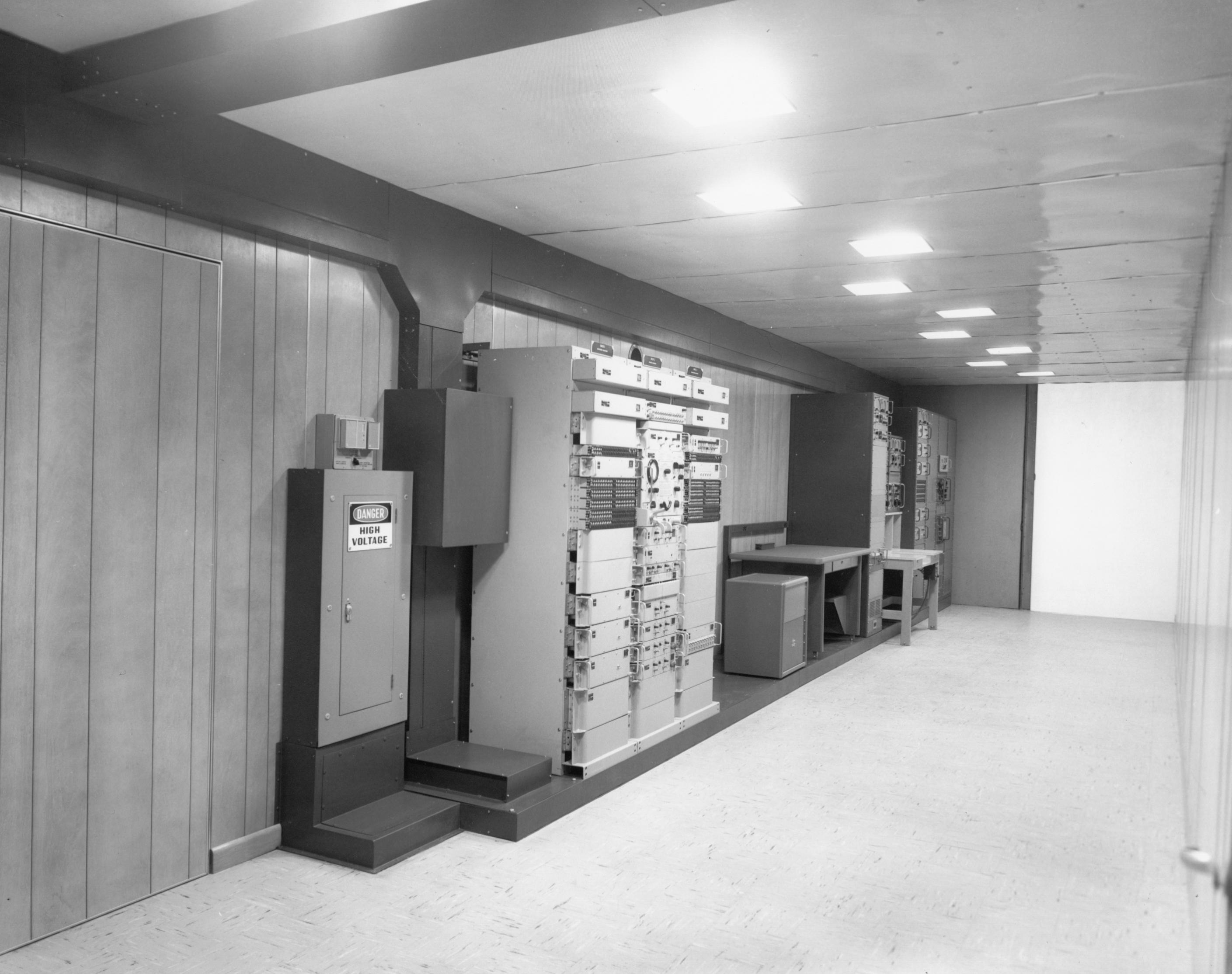
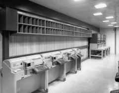
RE1 Unclassified Control - Container RE1 is the
Unclassified Control area of the Receiving Central. RE1 houses the BLACK
MDF and patchboard, eight 16-channel diversity full-duplex tone-telegraph
terminals, four 16-channel non-diversity full-duplex tone telegraph
terminals, three sets of 8-narrow and 4-wideband non-diversity tone
telegraph terminals, six point-to-point duplex order-wire and one station
order-wire TT-176A equipments, two TT-176A monitors, an AN/GGM-1
distortion measuring equipment, an audio spectrum analyzer, an audio
oscillator, a 20-channel "Fox" distribution amplifier, a BLACK
INTERCOM unit, a desk and a storage cabinet. |
RE1 - AN/FGC-60
 |
 |
RE1 - Unclassified Control - Black MDF
 |
RE1 - Unclassified Control - Black MDF
 |
RE1 - Black MDF
 |
RE1 - Unclassified Control
 |
RE1 - AN/FGC-60
 |
 |
RE1 - AN/FGC-60 during installation
 |
RE1 - Unclassified Control
 |
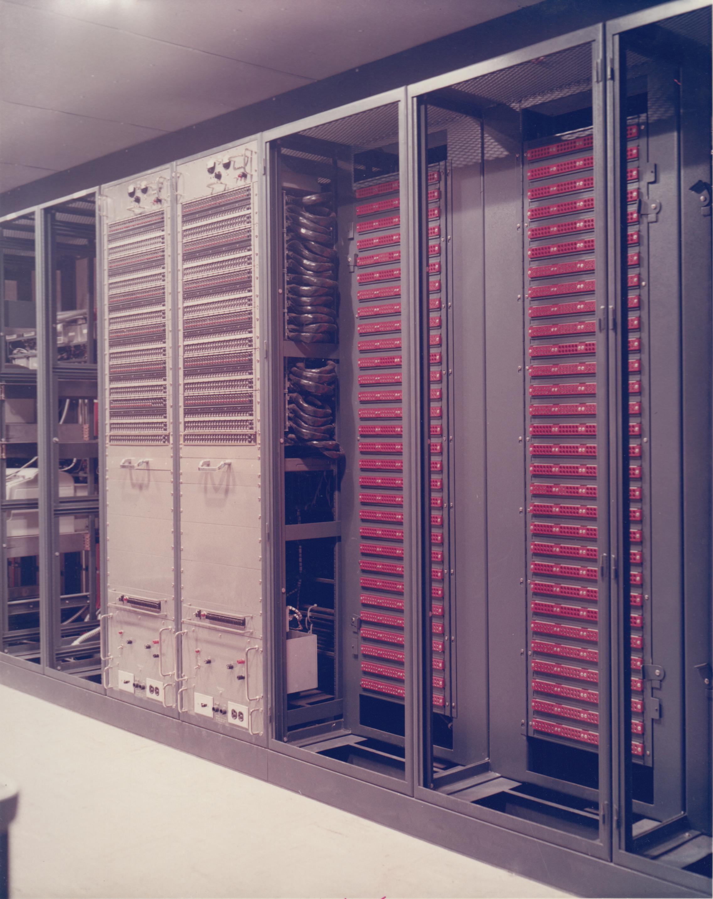
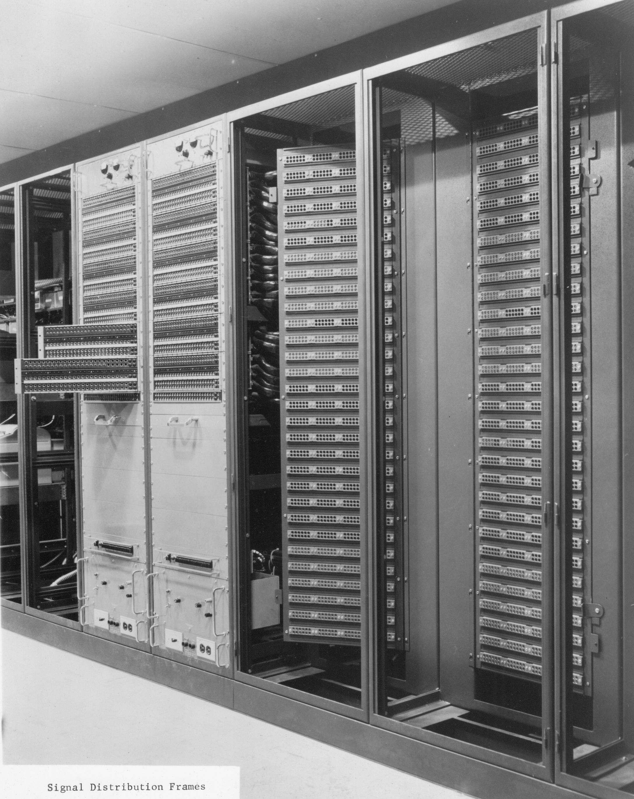
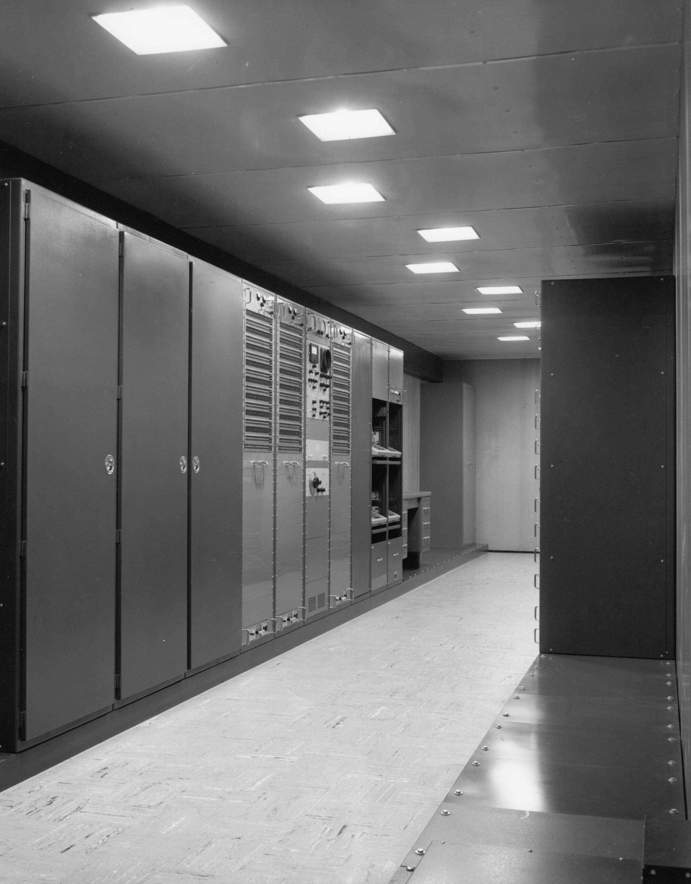
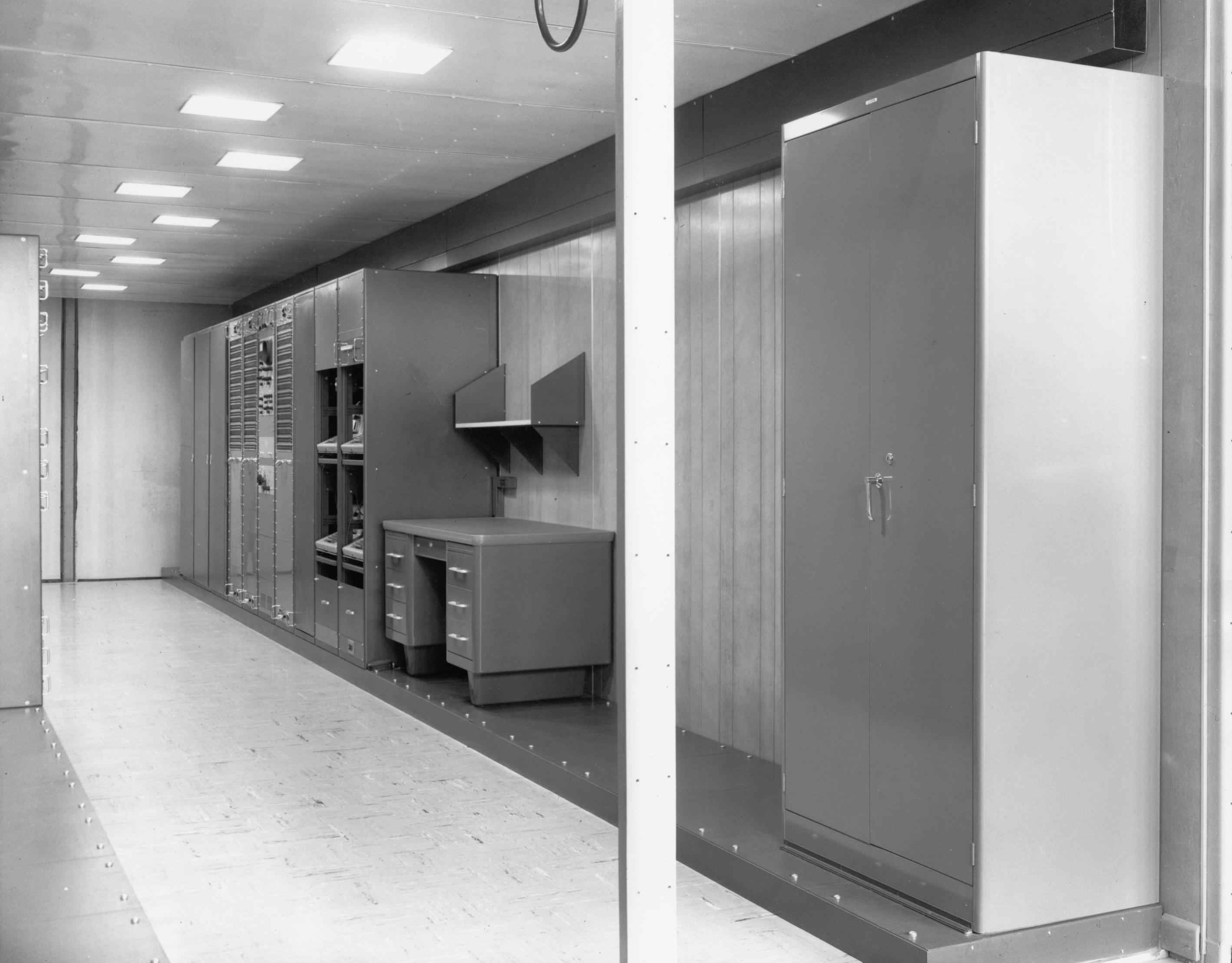
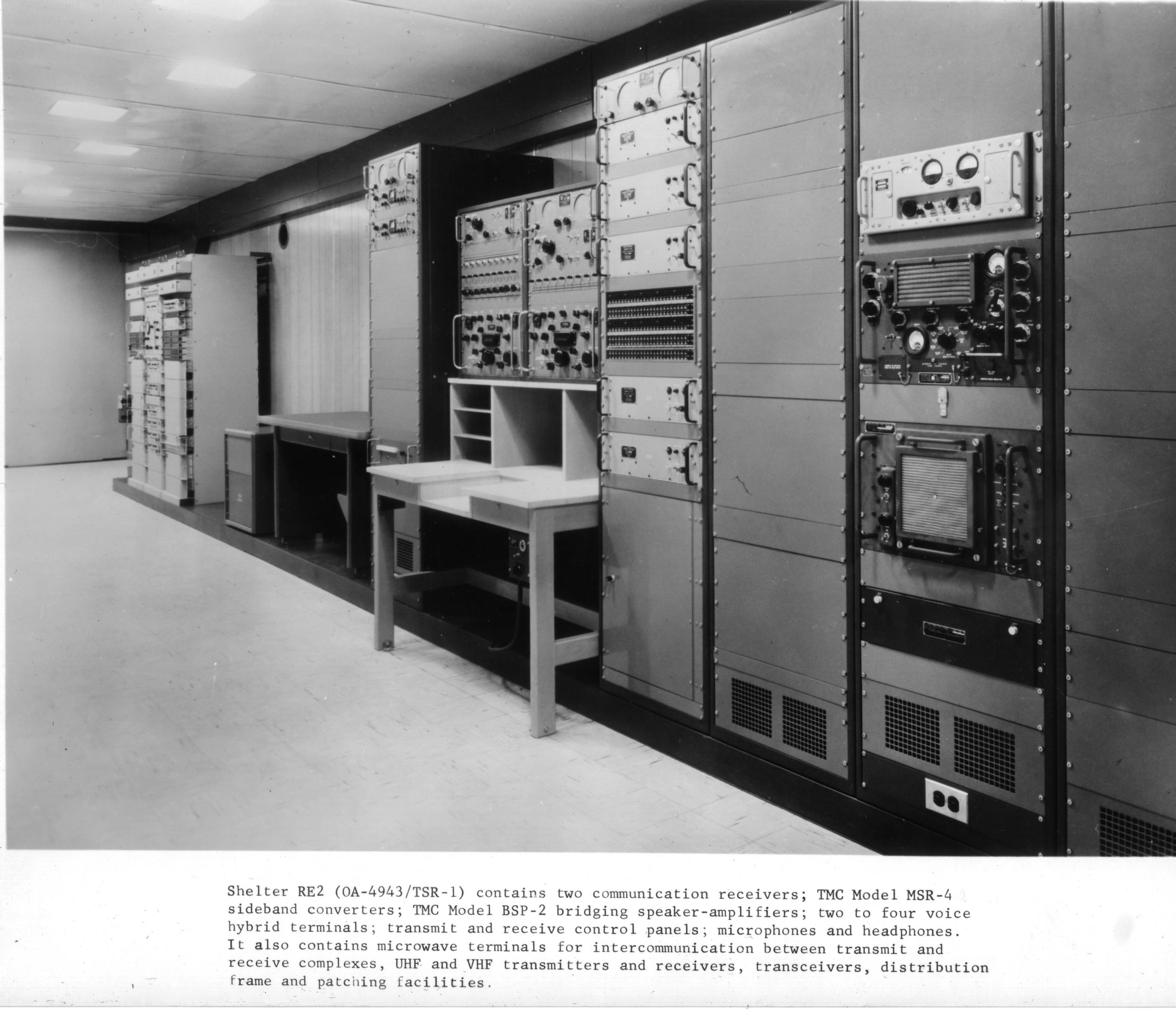
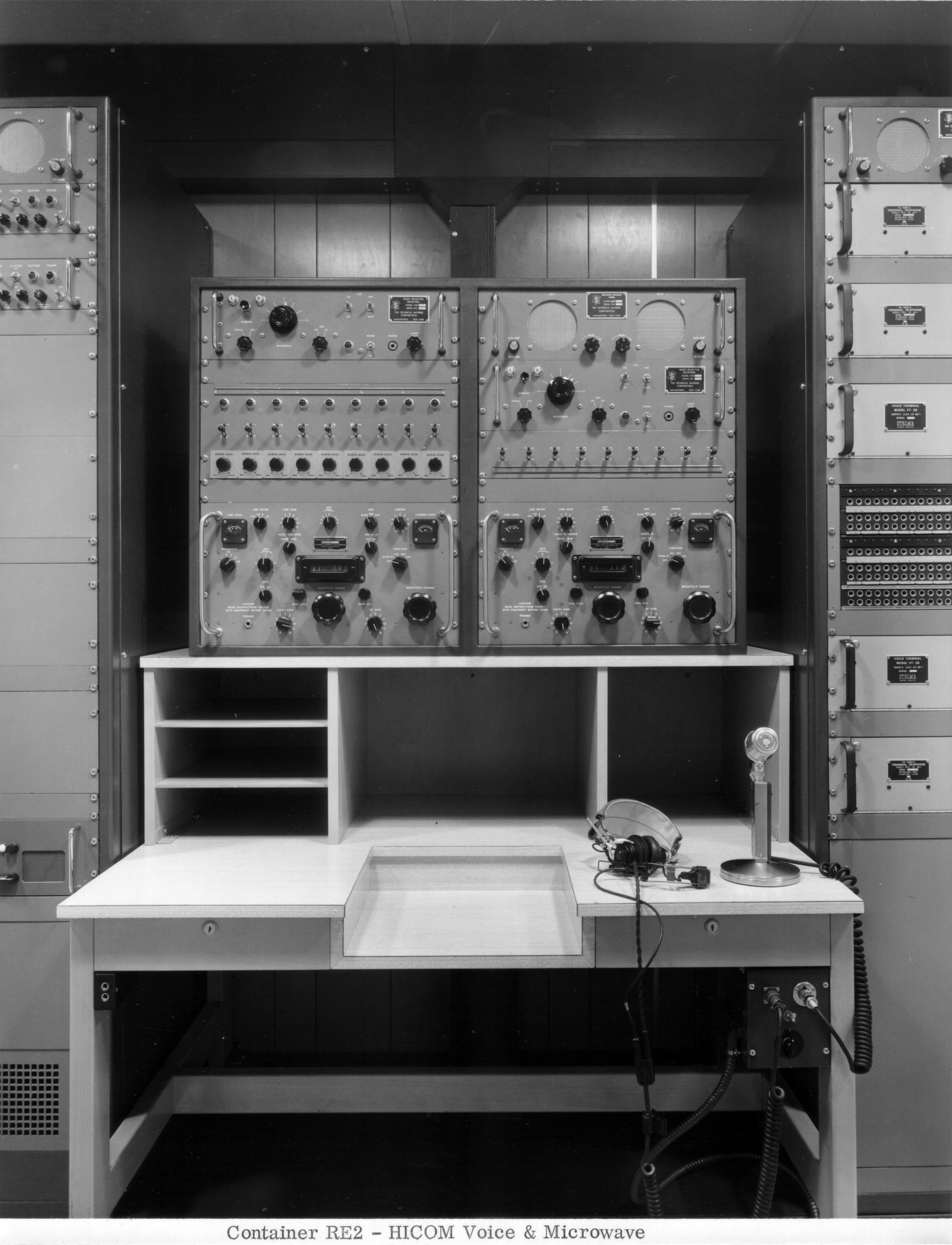
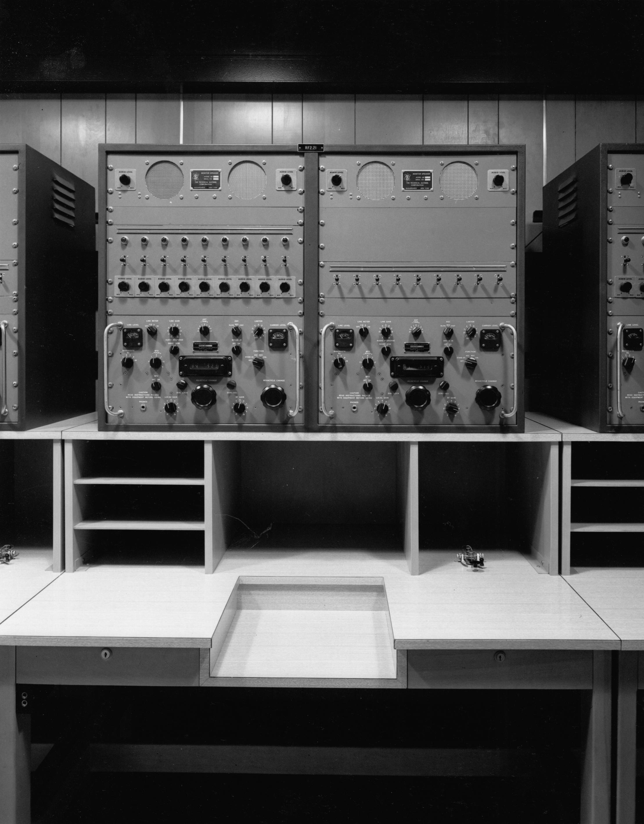
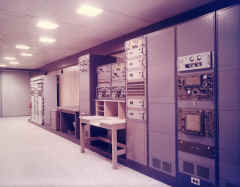
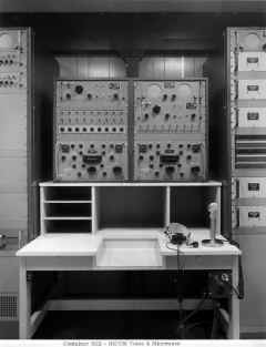
RE2 HICOM Voice & Microwave - Container RE2 is
the Voice and Microwave Operating area (see figure 1-21). The voice
operating position contains two R-390A receivers, two CV-591A SSB
converters, four BSP-2 speaker-amplifiers, five TA-401B voice terminals,
transmitter and receiver control panels, two microphones, and headphones.
The microwave terminal consists of 74B-1 transmitters and
receivers and an AN/FCC-17 voice terminal having 48-send and 12-receive
channels. The AN/FCC-17 is expandable to 60-send and 60-receive channels.
Additional equipment includes AN/URR-27 and AN/URR-35
receivers, AN/GRT-3 and AN/URT-7 transmitters, an AN/SRC-20 UHF
transceiver, a special distribution frame (SDF) with an associated
patchboard, a 2067 two-tone telegraph keyer, SPU-2 speech processing
units, a BLACK INTERCOM unit, and a dehydrator. |
RE2 - HICOM voice, microwave, & VHF

|
RE2
|
RE2- HICOM voice
|
-- |
RE2 - before installation
 |
 |
RE2 - during installation
 |
RE-2 during installation
 |
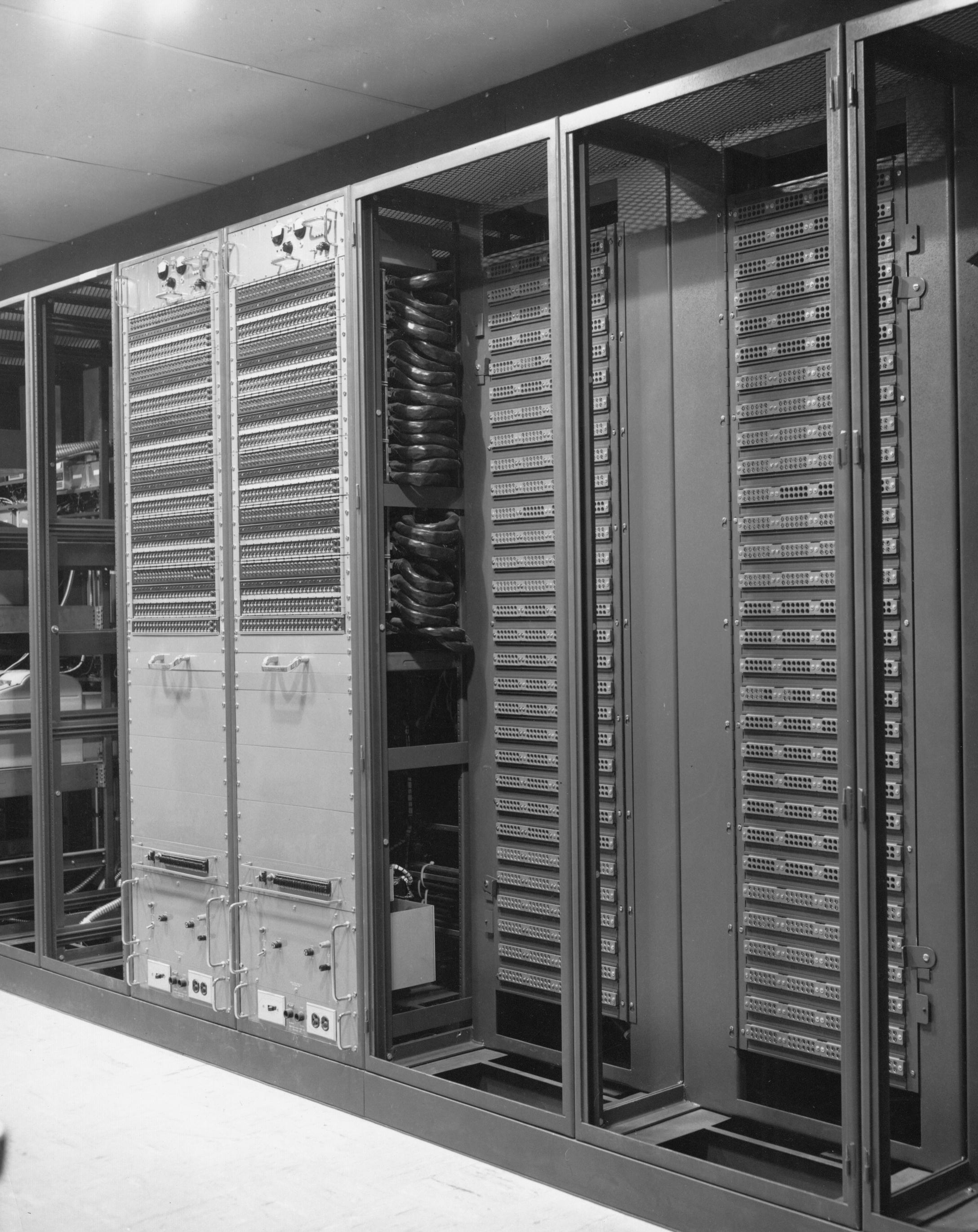
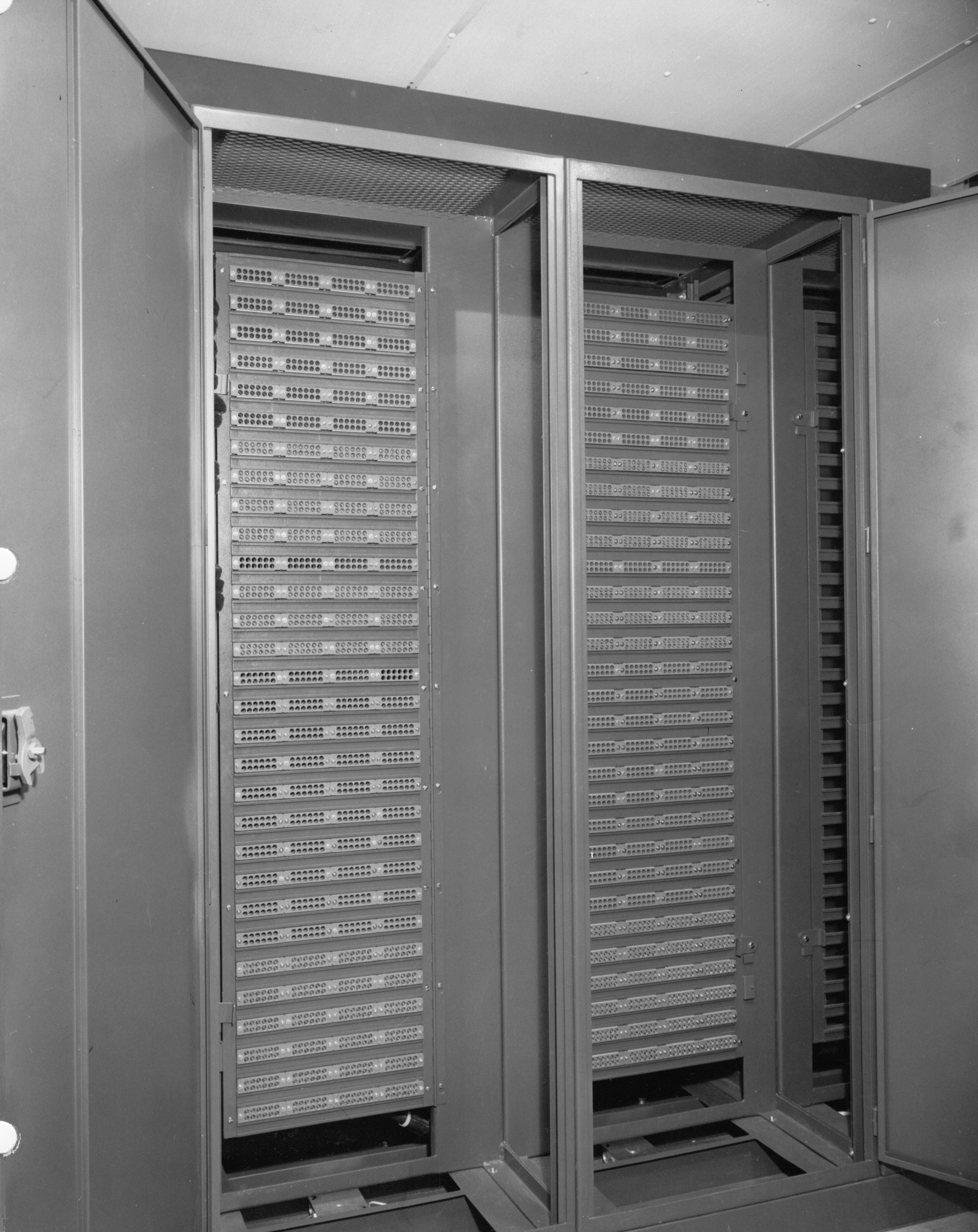
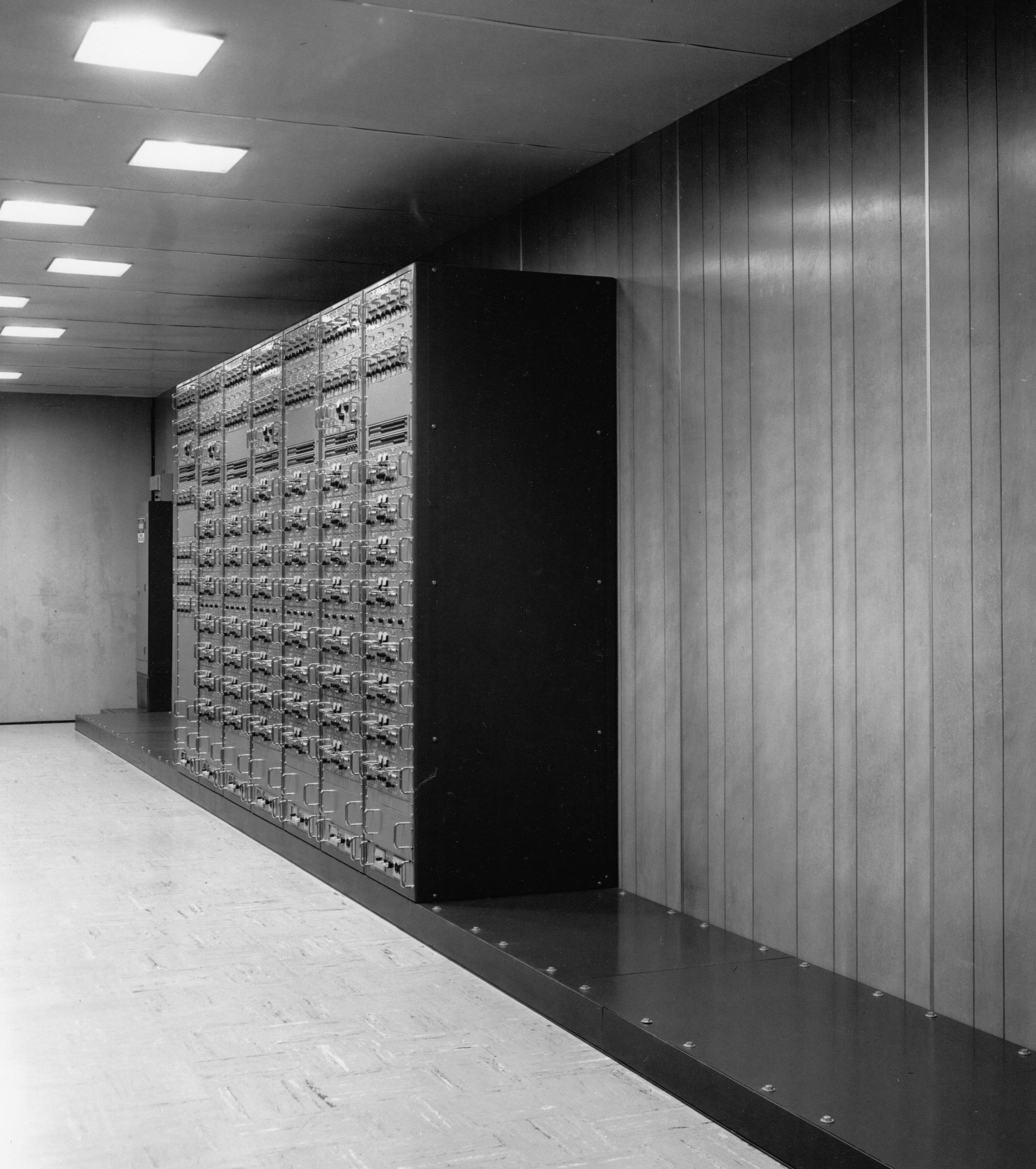
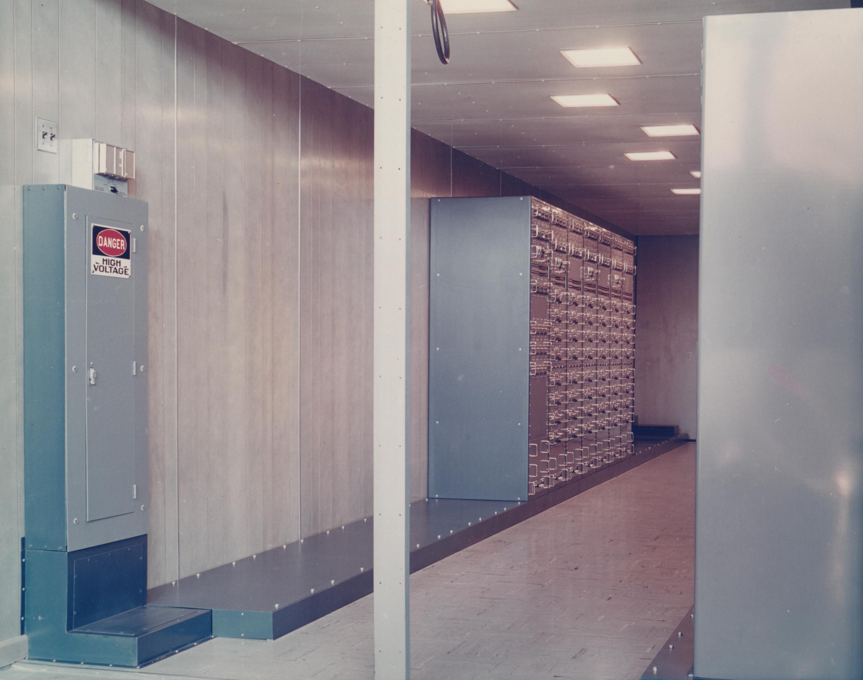
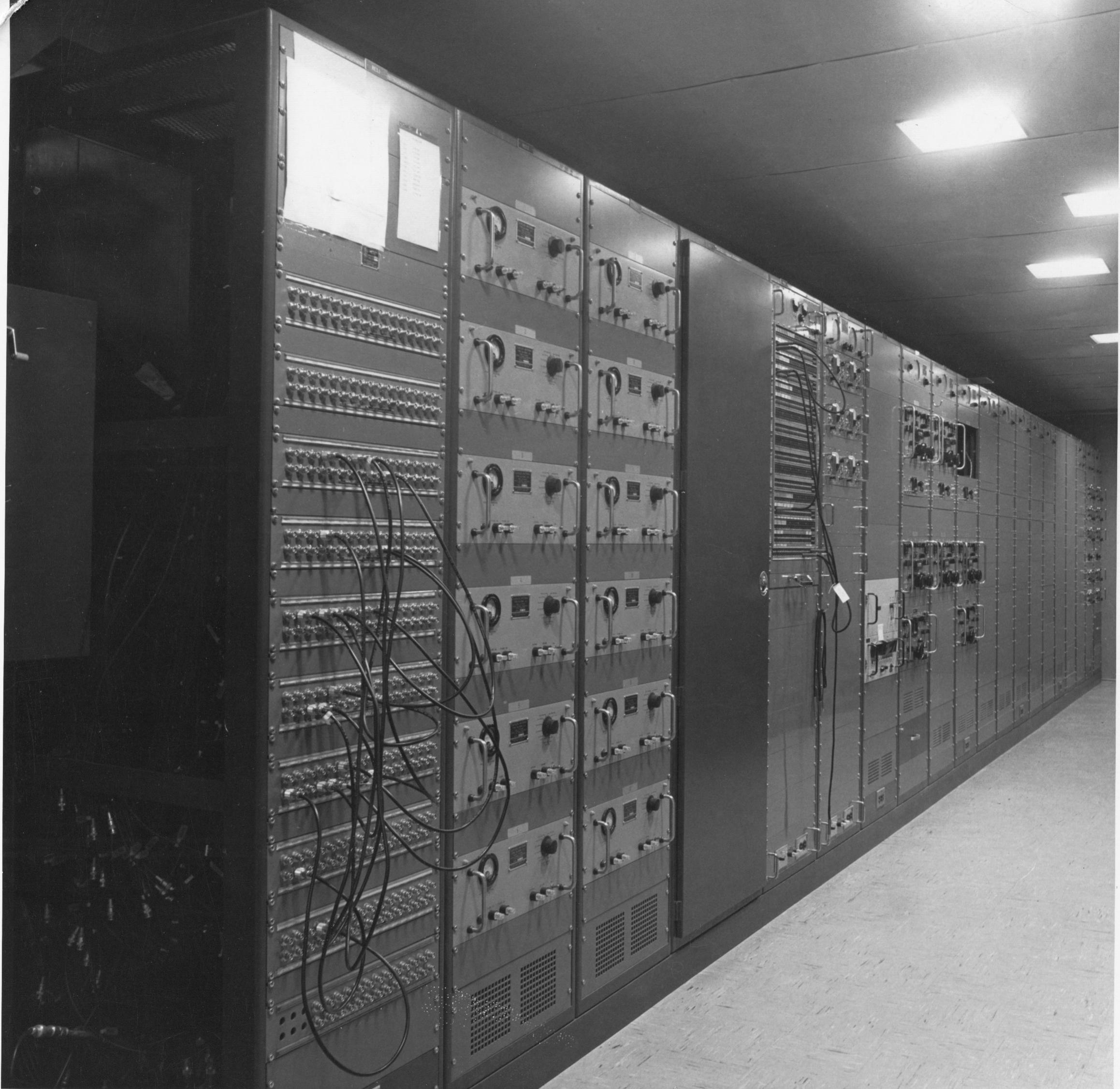
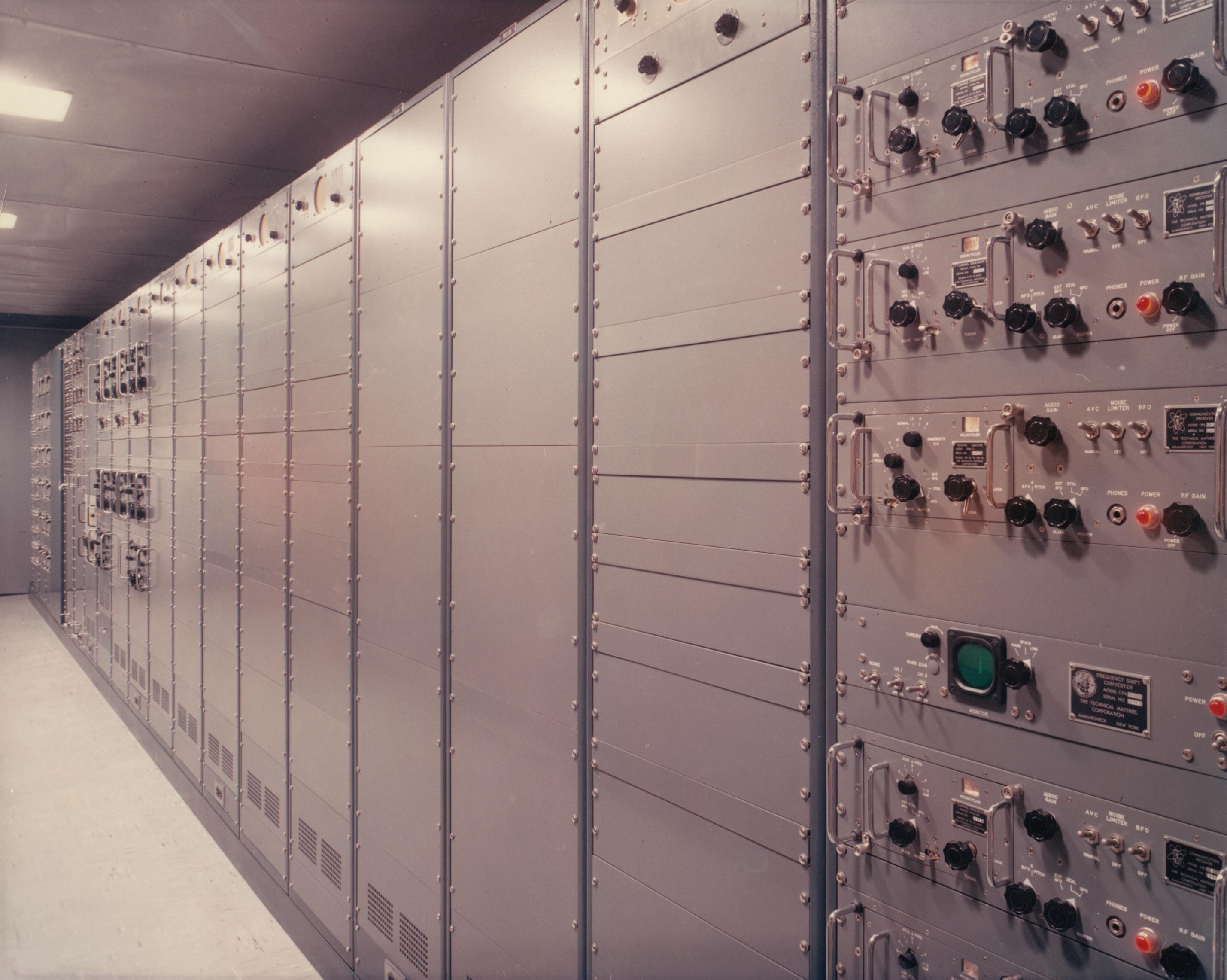
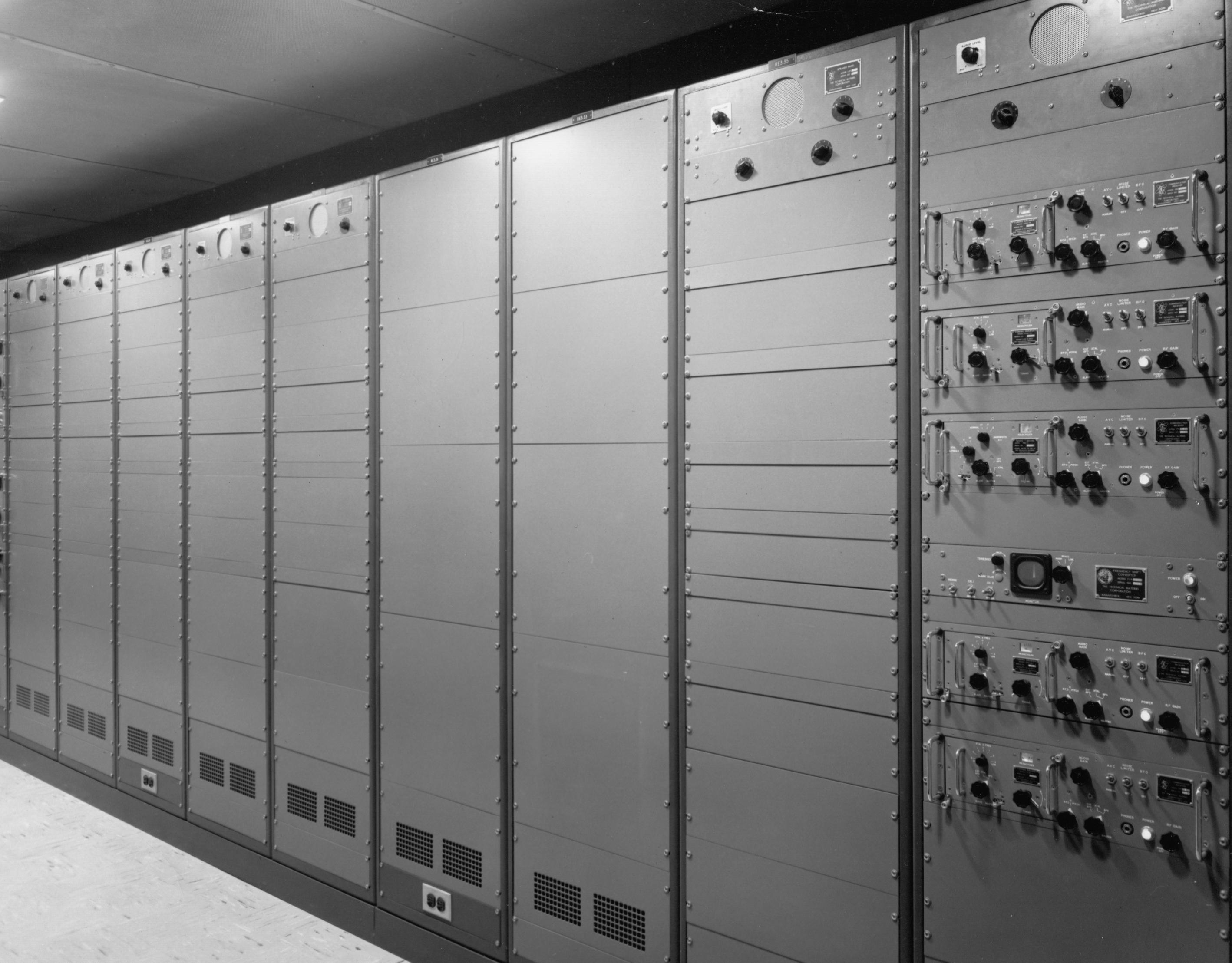
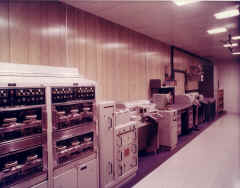
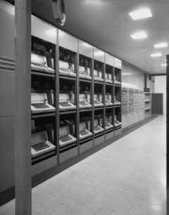
RE3 & RE4 Receivers - NOTE - At Nea Makri,
RE3 and RE4 equipments were combined into a single RE3 trailer, with just
three FRR-60 dual diversity receivers.
Container RE3, in conjunction with RE4, comprises the primary Receivers
area of the Receiving Central. Container RE3 houses six AN/FRR-60
dual-diversity synthesized SSB receivers, fifteen R-5007/FRR-502 monitor
receivers, sixteen R-390A receivers, four R-389 receivers, twenty-eight
frequency-shift converters, RLPA controls, a VLFC, the master station
clock, two TT-176A TTY's, sixteen TD-411/UGC demultiplexers, a receivers
intermediate distribution frame (IDF), a BLACK INTERCOM unit, and a desk.
Container RE4 is adjacent to RE3 and is part of the
primary receivers area. Equipment installed in RE4 includes three
AN/FRR-60 dual-diversity synthesized SSB receivers, one AN/FRR-60
non-diversity SSB receiver, an 80-line antenna patching facility, fifteen
CU-656 multicouplers with mounting provisions and wiring for twenty-one
additional units, one LFD-1 low-frequency RF distribution unit, and
facsimile equipment including a TT-321 transceiver, an AN/UXH-2 continuous
page recorder, an MD-168 modulator, a CV-1066 converter, and an R-390A
receiver. |
 |
RE3- antenna patch & multicouplers
|
RE3- antenna patch & multi couplers
 |
RE3- antenna patch & multi couplers
 |
RE3 - during installation
 |
RE3 - AN/FRR-502
|
RE3 - AN/FRR-502
 |
RE3 - AN/FRR-502
 |
RE3 - Receivers (AN/FRR-60)
 |
RE3 - Receivers (AN/FRR-60)
 |
RE3 - Receivers (AN/FRR-60)
 |
RE3 - (12/63) after installation
 |
RE3 - after+++ installation (12/63)
 |
|
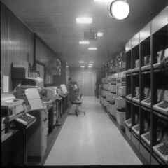
RF1 Message Center - Container RF1 is the message
center of the Receiving Central. Teletype equipment installed in RF1
includes two AN/UGC-5 units for NTX and Pony send circuits, two AN/UGC-6
units for Run-Off and Make-up positions, six TT-176A monitors, one
TT-47for internal order-wire, and a 3-line AN/FGC-59 torn-tape relay
facility consisting of one each TT-331 receive group, TT-333 transmitter
group, and TT-332 transmit monitor group. This TT-333 transmitter group is
not equipped for tandem operation. Desks are provided for the CWO,
supervisor, traffic checker, and two routing positions. RED INTERCOM units
are shelf-mounted above the CWO's desk and above the supervisor's desk.
Storage facilities for monitor reels, tapes, and paper supplies are
provided in two cabinets. |
 |
RF1 - Message Center
 |
RF1 - Message Center
 |
RF1 - Message Center
 |
RF1 - Message Center
 |
|
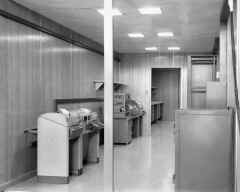
RF2 CW Ship/Shore - Container RF2 is the CW Ship/Shore operating area of
the Receiving Central. RF2 contains three CW operating positions, two equipped
with two R-390A receivers, and one with two R390A receivers and one R389
receiver. Each position also contains dual speaker-amplifiers, hand keys, a
transmitter control panel, and a receiver control panel. Teletype equipment
provided in RF2 includes four AN/UGC-8 weather positions, one AN/UGC-6 and one
TT-47 for pony circuits, two AN/UGC-6 and two model 660A electronic TTY-to-Morse
code converters for CW/RATT broadcast operations, one TT-176A off-air monitor,
and a TT-47 internal order-wire unit. Furniture includes a desk, a filing
cabinet and a pigeon-hole tape-storage cabinet. A BLACK INTERCOM unit is
mounted above the desk. |
 |
RF2 - CW Ship/Shore
 |
RF2 - CW Ship/Shore
 |
RF2 - CW Ship/Shore
 |
RF2 - CW Ship/Shore
 |
|
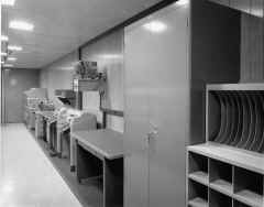
RF3 Air/Ground - Container RF3 is the Air/Ground operations area of the
Receiving Central and provides storage for message files and paper supplies. A
partition divides the operations from the storage area. The operations area
contains three operating positions, each equipped with a transmitter and a
receiver control panel, a CV-591A SSB converter, two dual and one single
speaker-amplifier units, a hand-key, two microphones, a microphone footswitch,
and two R-390A receivers. A clothes locker is provided in this area. The
storage area is equipped with three rows of racks for storing messages and
supplies. |
RF3 Air/Ground Operations
 |
RF3 Air/Ground Operations
 |
RF3 Storage
 |
RF3 Storage
 |
|
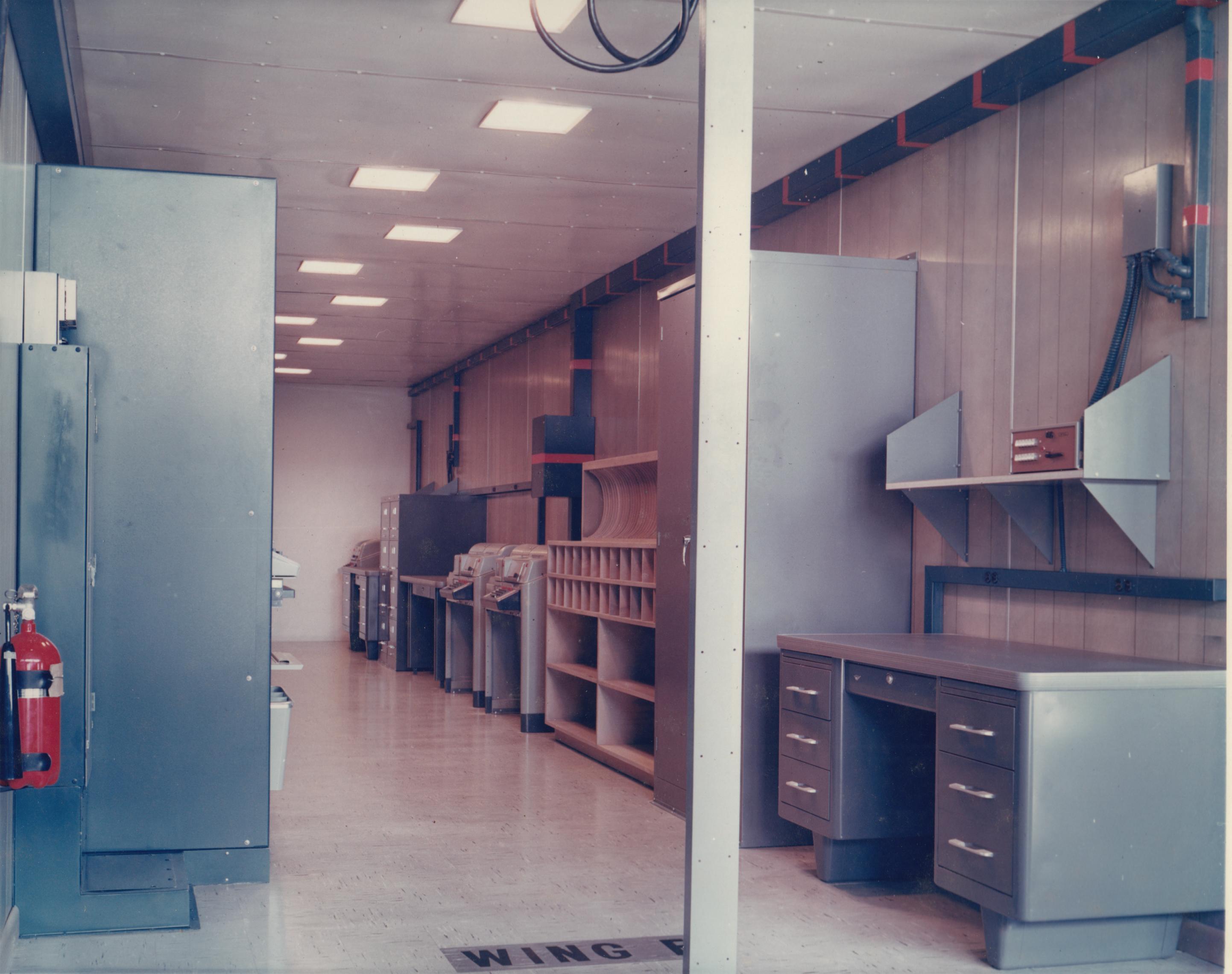
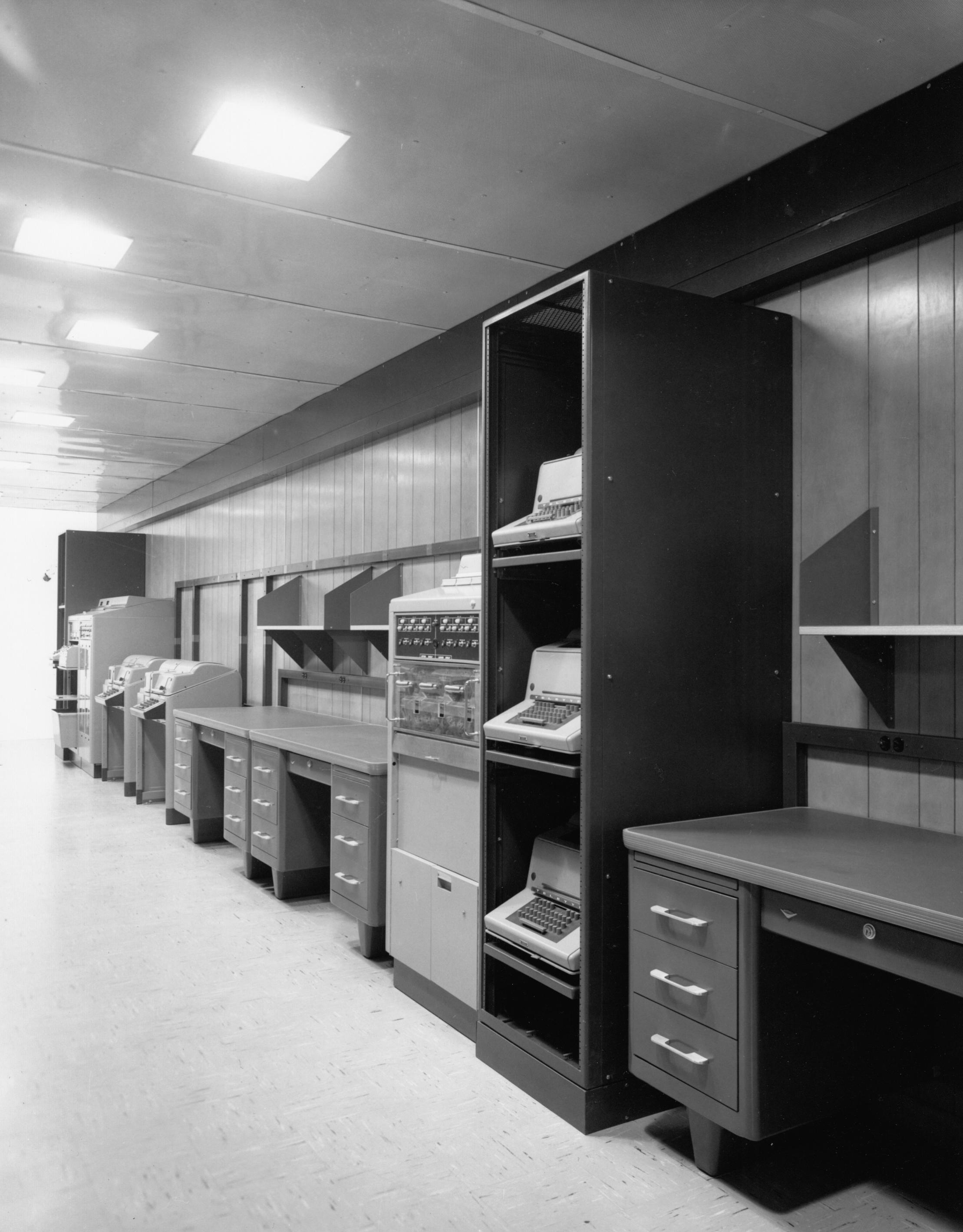
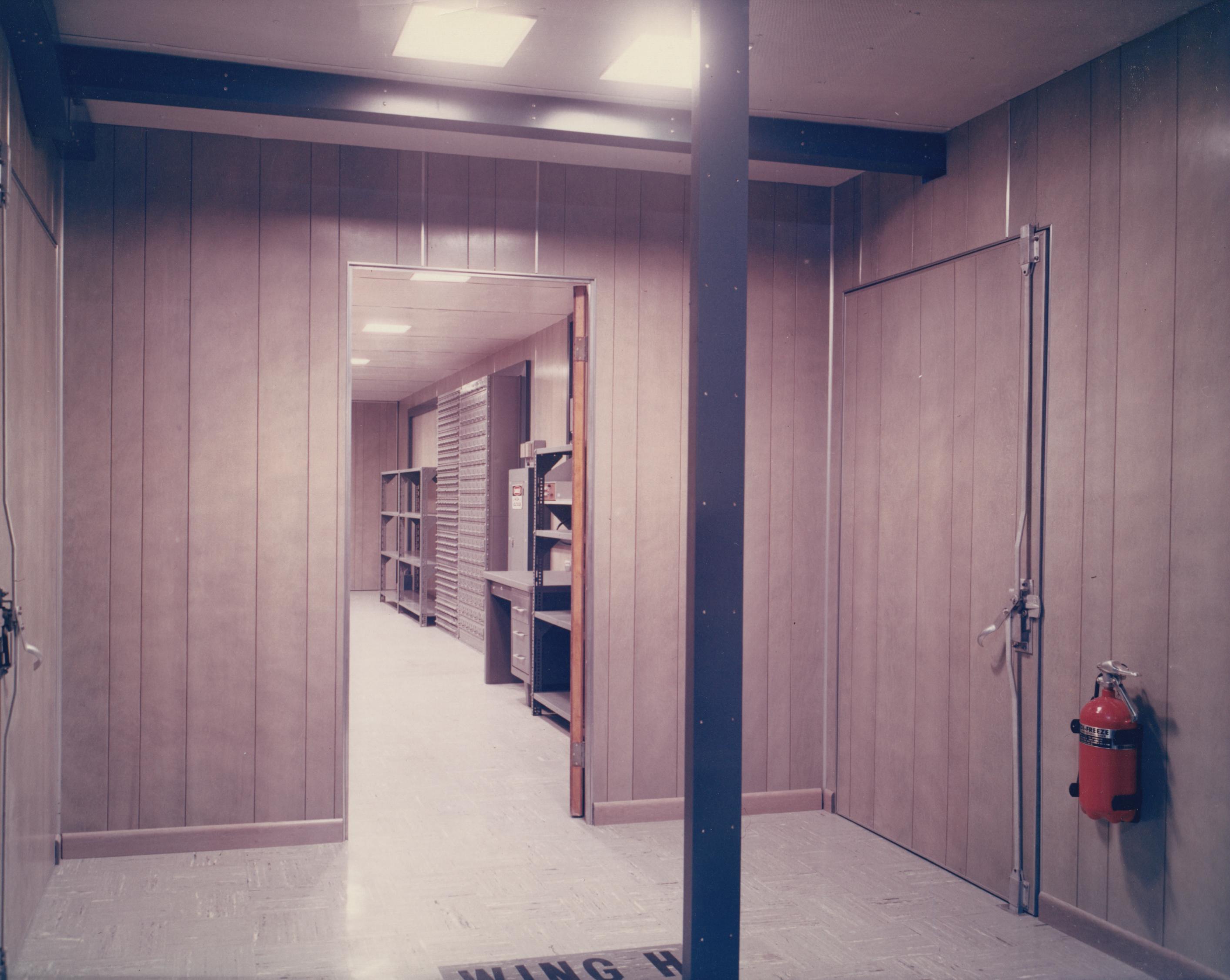
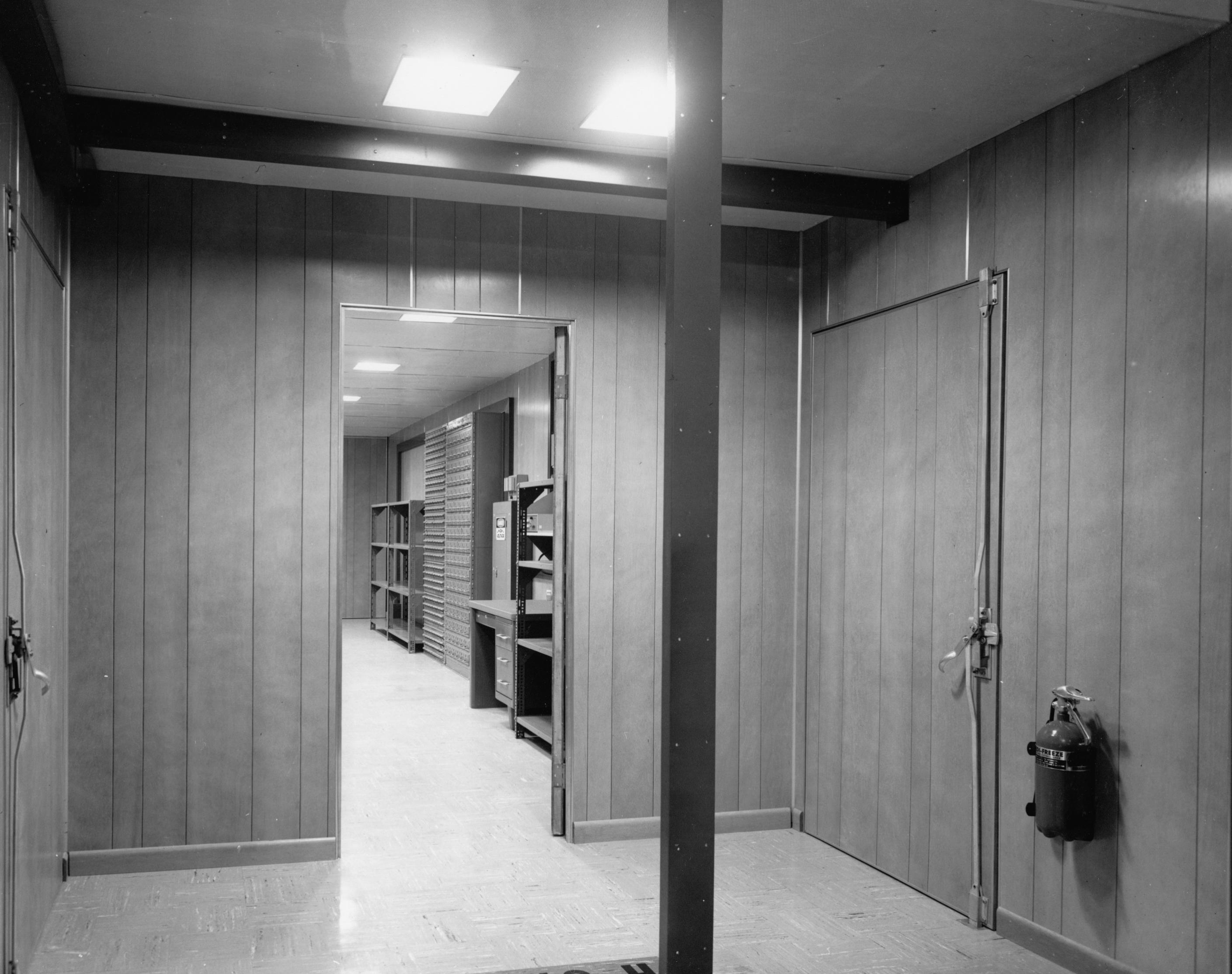
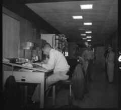
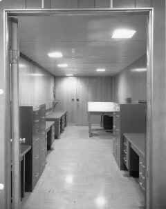
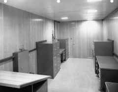
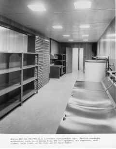
RG1 Communication Office - Container RG1 is the
Communication Office and provides the main entrance to the Receiving Central.
Communication office equipment includes six desks, six filing cabinets, a
drafting table, and both RED and BLACK INTERCOM units. The forward end is a
large vault with a manipulation-proof combination lock door. The rear area is
partitioned to form an entrance foyer. The foyer has two doors to the outside
and one into the office area. |
 |
 |
RG1 - Communication Off ice
 |
|
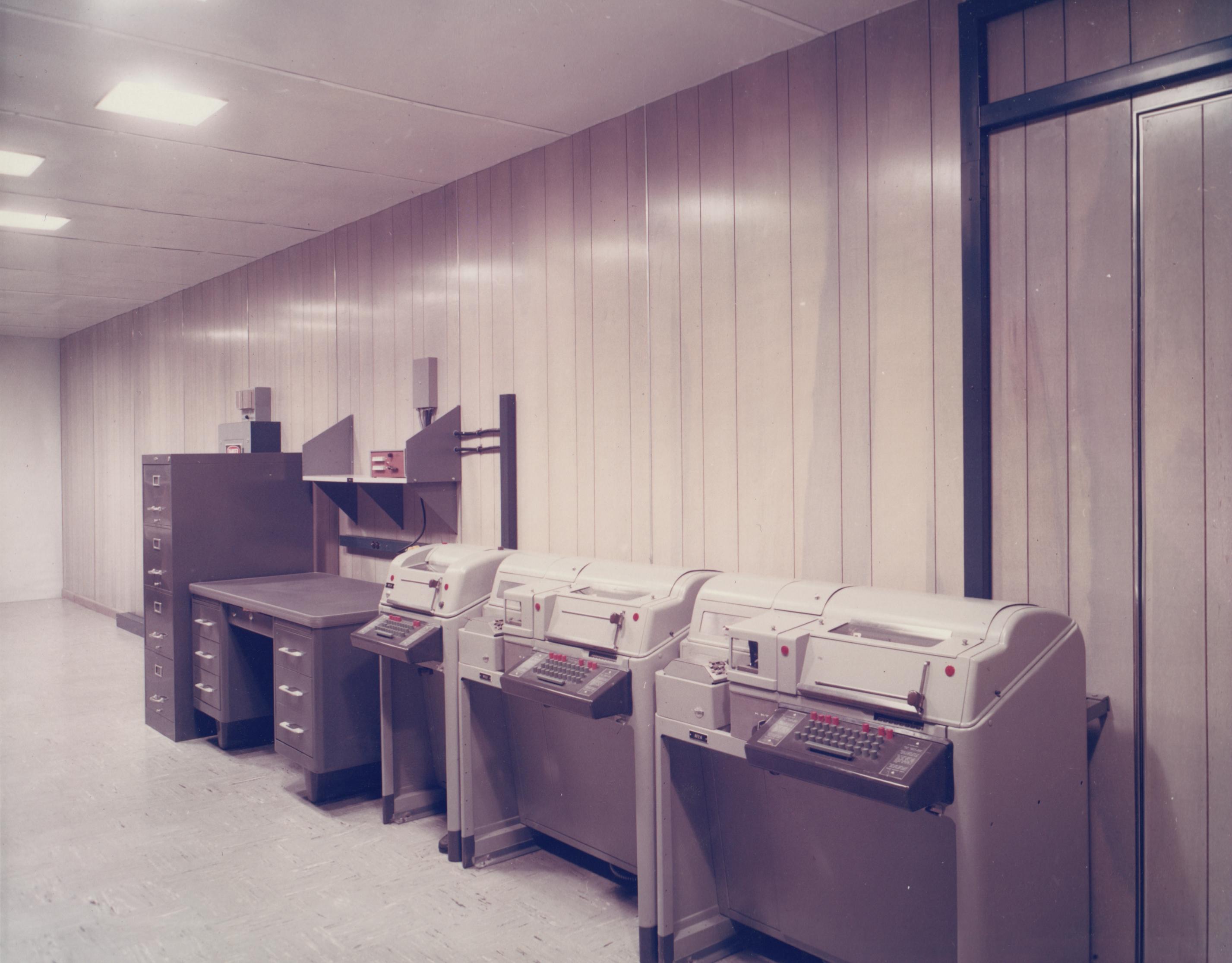
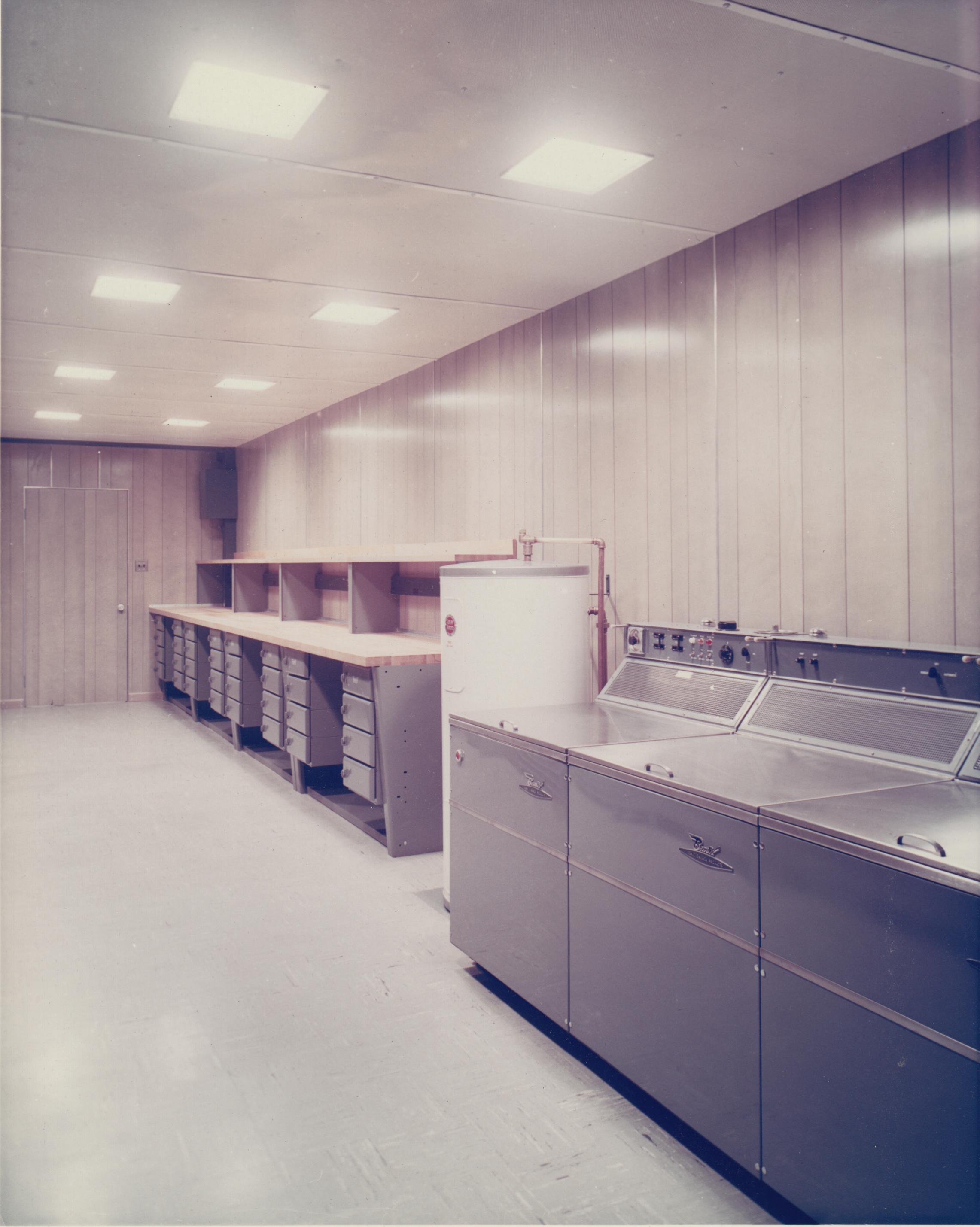
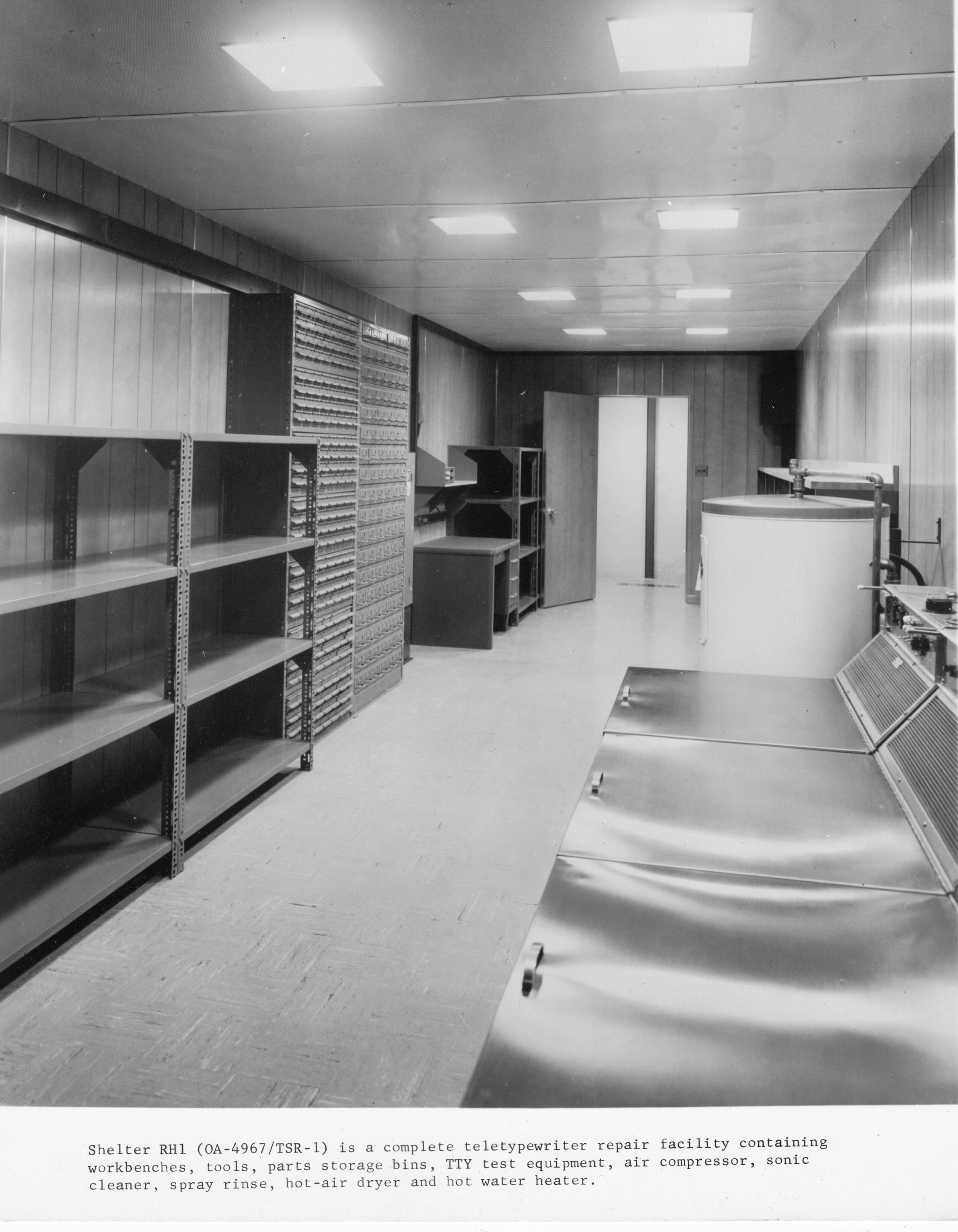
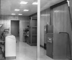
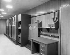
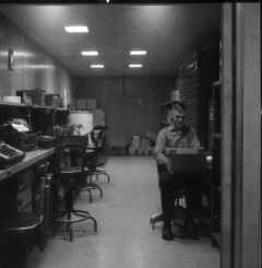
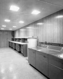
RH1 TTY Repair - Container RH1 is the TTY repair shop. RH1 contains
workbenches, tools, parts storage racks, TTY test equipment, a BLACK INTERCOM
unit, a desk, an air compressor, a sonic cleaner, a spray rinse, a hot-air
dryer and a hot water heater. |
RH1 - TTY Repair
 |
RH1 - TTY Repair
 |
RH1 - TTY Repair
 |
RH1 during installation
 |
 |
 |
 |
|
|
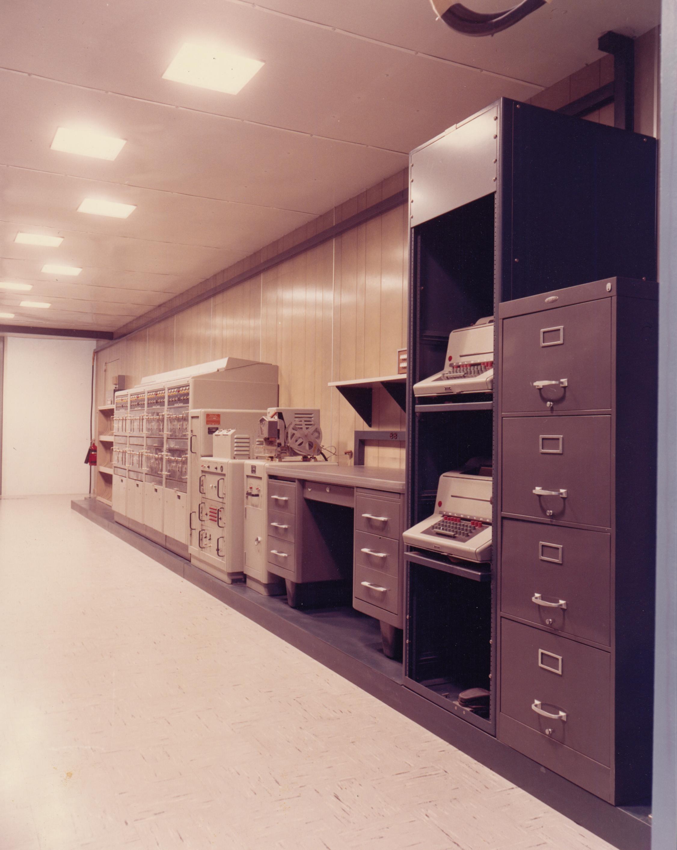
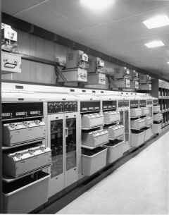
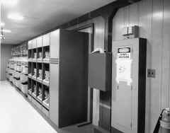
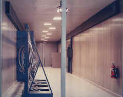
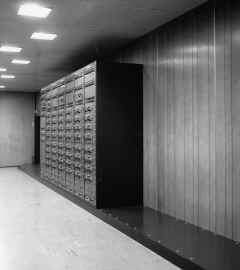
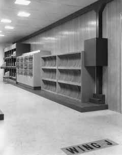
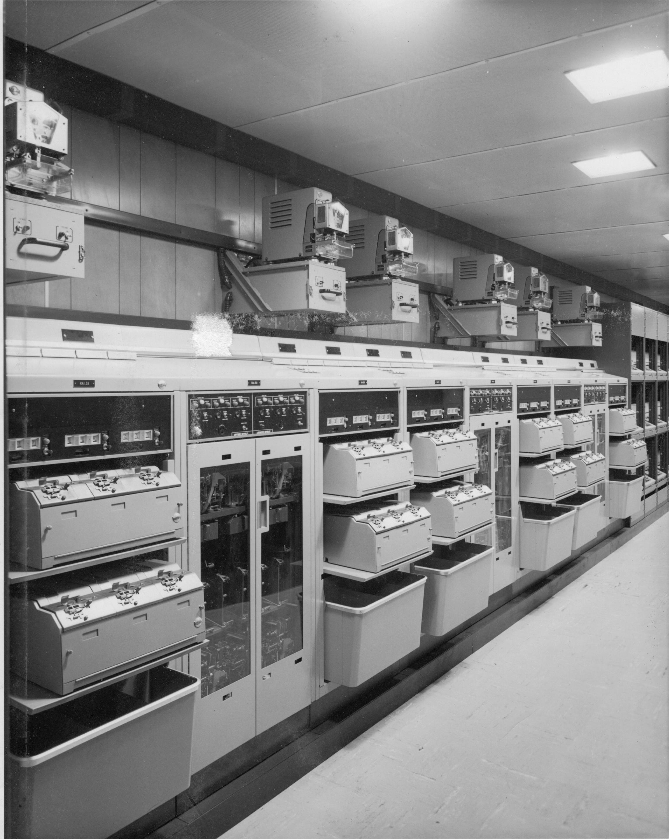
RJ1 NTX Receive - Containers RJ1 and RJ2 comprise the NTX torn-tape relay
facility of the Receiving Central. Container RJ1 houses a 48-line NTX receive
torn-tape relay facility. Teletype equipment provided in RJ1 includes eight
TT-331 Teletype Receive Groups, nineteen TT-176A page copy monitors, a monitor
patch panel, an AN/FGC-73 routing console, a TT-329 high speed reperforator for
NTX overflow, an AN/UGC-6 for correcting tapes, and a TT-176A station internal
order-wire unit. Furniture provided in RJ1 includes two monitor reel storage
cabinets, a supervisor's desk, and two filing cabinets. A RED INTERCOM unit is
shelf-mounted above the desk. |
RJ1 - NTX Receive
 |
RJ1 - NTX Receive
 |
RJ1 - NTX Receive
 |
RJ1 looking toward RJ2
During installation
 |
 |
-- |
-- |
-- |
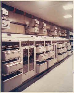
| RJ2 NTX Transmit - Container RJ2 houses a 48-line NTX
send torn-tape relay facility. Teletype equipment provided in RJ2 includes
sixteen TT-333 Teletype Transmitter Groups, eight TT-332 Transmit Monitor
Groups, sixteen TT-329 High-speed Reperforators, and two AN/UGC-6 units
for tape makeup. The TT-333 Teletype Transmitter Groups are equipped for
tandem operation. The TT-329 High-speed Reperforators are fed NTX messages
by the AN/FGC-73 routing console which is located in container RJ1. |
RJ2 - NTX Transmit
 |
 |
 |
 |


