Transportable Navy Communication Stations
AN/TSC-24
Air Transportable Communications Unit
- 3 shelters (ATCU-100) or 5 shelters (ATCU-100A) plus diesel generators
- can be airlifted via 1 C-133 or 2 C-124's or CH-47 Chinook sling
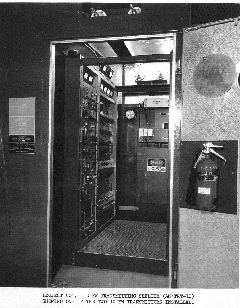
(Technical Materiel Corp. Project
Dog)
- ATCU-One - ATCU-100A deployed from Honolulu to Can Tho, Vietnam March 1966 - Photos
and Info
- "The
rapid development of plans for increased river patrol force operations
in South Vietnam created an urgent requirement to provide CTF 116 with a
communications capability in the Can Tho area, An engineering team was
in Vietnam conducting a survey to provide plans for permanent
communications facilities at Can Tho. Pending completion of permanent
communications facilities, an Air Transportable Communication Unit
(ATCU-100A) from U. S. Naval Communication Station, Honolulu, was being
modified for use at the Can Tho site by 15 March. Until permanent
personnel were assigned by CTF 116, a total of two officers and
thirty-four enlisted men from Honolulu and Japan would operate and
maintain the unit."
- ATCU-Two - NavCommSta Puerto Rico
- ATCU-Three - ATCU-100A deployed from Philippines to Da Nang, Vietnam
1966-?
- ATCU-Four - ATCU-100A deployed from NavCommSta Washington DC to Ambala Air Force Base, India
1963
- ATCU-Four - ATCU-100 deployed from Norfolk to Diego Garcia 1971-72 to support SeaBees building
the permanent station
- ATCU-Five - ACTU-100A deployed from Norfolk to Key West 1962-1969 - Photos
- positioned at NRTF Driver - 1979 deployed to Camp Lejeune for an
exercise?
- ATCU-Six - NavCommSta Japan - deployments?
- ATCU Six - 1977 transferred
from Lulualei HI to NAVCOMMSTA Philippines
- ATCU-Seven - ATCU-100 deployed from Philippines to U-Tapao, Thailand 1968-? - Photos
- ATCU-Eight - ATCU-100A deployed from Honolulu aboard USS Yorktown for Apollo 8 recovery - 1968
- ATCU-Nine - ATCU-100 moved from Washington DC to Philippines 1967
- ATCU-Nine? - ATCU-100 deployed from Philippines to Cam Ranh Bay, Vietnam March-May 1967
- ATCU-Nine - ATCU-100 deployed from Philippines to Yongsan, Korea to provide
communications following USS Pueblo incident, January 1968 - Photos
- ATCU-Nine - ATCU-100 deployed from Philippines to Yongsan, Korea for joint
ROK/US Marine exercise - late
1970's
- Harold Miller says "
22 Sailors and 3000 marines. Darned cold before we got our vans, we
were all in Tropical greens, and there was snow on the ground. I
remember walking in circles in an old movie theater with about a
thousand other freezing folks...
Anyway, we had a Transmitter Van, a Receiver Van, and my home was the
Crypto van. We used a big inverted V antenna with florescent lights
tubes tied to it, so the grunts wouldn't grab it when we were
transmitting (the RF would make the tubes glow)"
- ATCU-Ten - ATCU-100 deployed from Port Lyautey to Morocco Royal Palace March-April 1963 - Photos
and Info
- ATCU-Eleven - ATCU-100A deployed from Rota to Decimomannu Air Base,
Sardinia 1966
- ATCU-Twelve - Londonderry ATCU-100A - deployed to Thurso 1963 then
where???
- ATCU-?? - ATCU-100 at Nea Makri Greece
- ATCU-?? - ATCU-100 at Guam
-
- Were there others? Please send e-mail with
any info or photos
|
Typical ATCU van and antenna layout
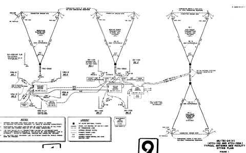
|
Capabilities 
- HF 16 channel frequency-division multiplex (AN/FGC-60)
- HF 4 channel time division multiplex (AN/UGC-1)
- VHF single channel (AN/SGC-1)
- UHF single channel (AN/SGC-1)
Receiver-Control Shelter AN/TRR-16
- 4 R-390A/URR HF receivers
- 2 CV-591/URR SSB converters
- 1 AN/URA-42 SSB converter
- 2 CV-763/URR RTTY converters
- 1 R-450/URR HF receiver
- 1 AN/FRR-21 LF receiver
- 2 KWM-2A HF transceivers (1 fixed, 1 portable)
- 2 AN/FGC-60 TTY multiplexer
- 2 UGC-1 TTY multiplexer
- 4 HF receiving whip antennas
- 1 HF receiving sloping vee antenna
- 1 HF transceiver whip antenna
- 1 LF receiving whip antenna
- 4 TT-187 TD
- 2 TT-192 reperf
- 7 TT-176A (28KSR) printers
- 2 KWT-26/KWR-26 crypto units
Medium Power Transmitter Shelter AN/TRT-12
- 4 1 kw AN/URT-19(V) HF transmitters
- 1 AN/URT-7 VHF transmitter
- 1 AN/URR-27 VHF receiver
- 1 TED-9 UHF transmitter
- 1 AN/URR-35 UHF receiver
- 4 AN/URA-27 HF antenna couplers
- 4 35' HF whip antennas
- 1 sloping vee HF antenna
- UHF and VHF antennas
High Power Transmitter Shelter AN/TRT-13 (ATCU-100A only)
- 2 10 kw AN/FRT-39B HF transmitters
- 2 sloping vee antennas
Relay Shelter OA-3773/TSC-24 (ATCU-100A only)
- RATT patch panels
- 8 TD + reperf (Send loops)
- 8 reperf (Receive loops)
- 2 spare TT-192 reperf
- 2 spare TT-187 TD
- 3 TT-176A (28KSR) page printers
- 8 KWT-26/KWR-26 crypto units
Repair and Maintenance Shelter
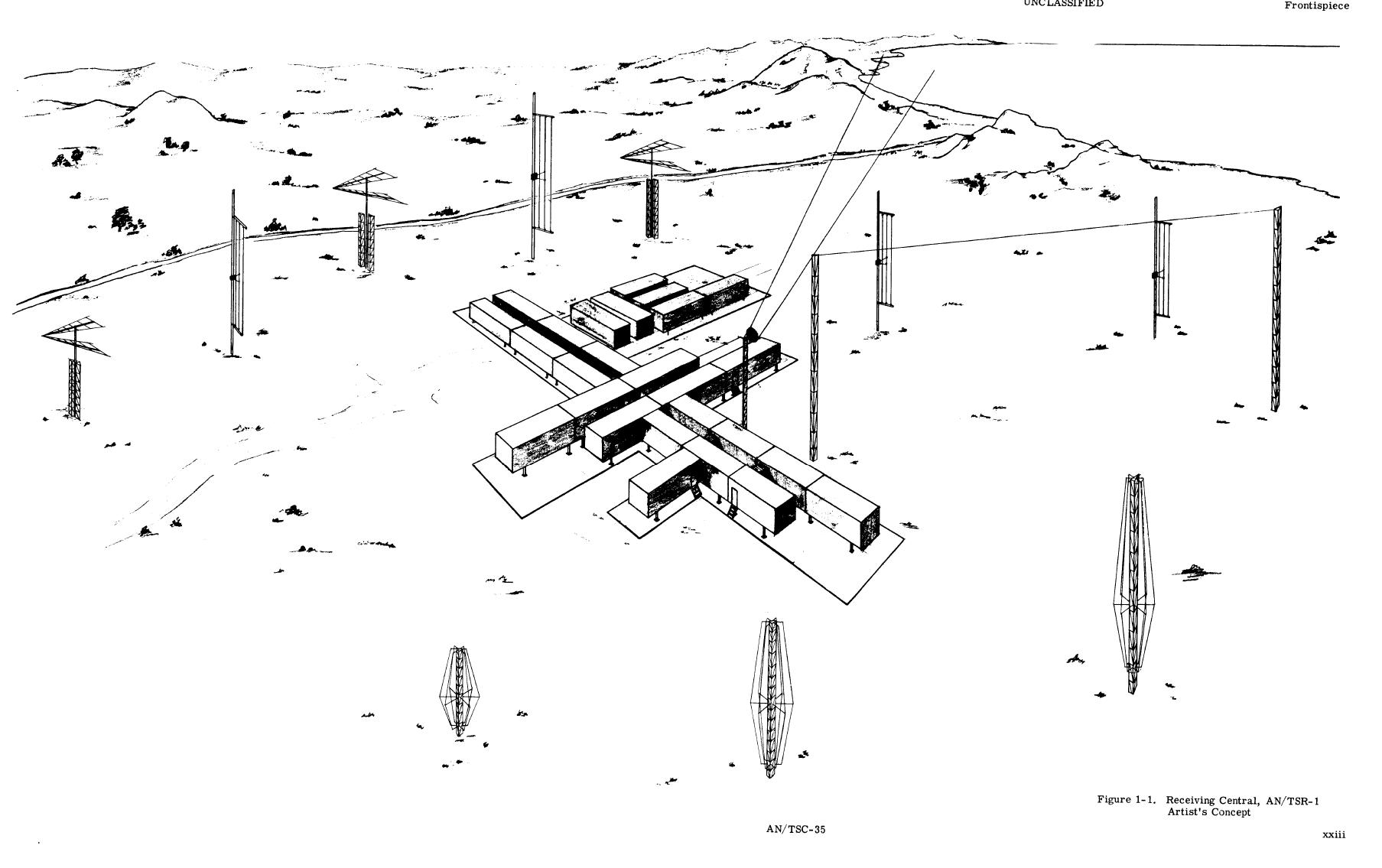
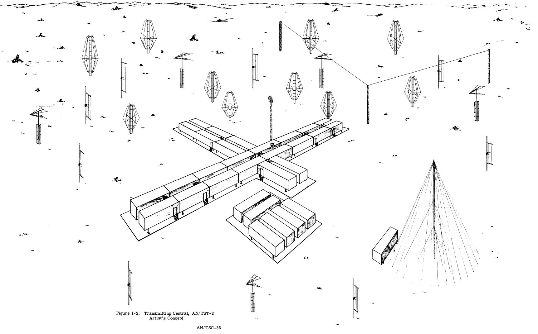
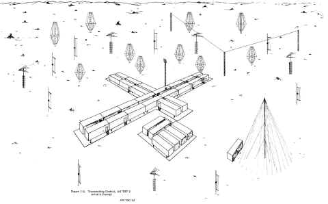
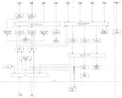
The U. S. Navy Transportable Communication System AN/TSC-35 is a complete
communication station consisting of a Receiving Central AN/TSR-1
(COMMCENTER/Receiver site) and a Transmitting Central AN/TST-2 (Transmitter site). (See artists concept of completed sites, figures
1-1 and 1-2.) Communication equipment, repair, supply, and primary power facilities at both sites are housed in 40-foot
containers which have been designed for land or sea transport and for rapid on-site installation. Associated transmitting and receiving antennas, primarily in kit form, can likewise be installed in a minimum of time. The assembled communication system provides point-to-point, ship-shore, air-ground and broadcast
communication facilities, with cryptographic capability, of the extent and
quality comparable to a fixed shore communication station.
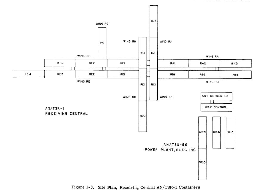
Communication System AN/TSC-35 is comprised of 26 containers at the Receiving Central
AN/TSR-1 arranged as shown in figure 1-3, 30 containers (and a Helix container which is not shown) at the
Transmitting Central AN/TST-2 arranged as shown in figure 1-4, and one mobile workshop trailer. The containers at each site (except for the power group, the mobile workshop trailer and Helix container) are joined
together end-to-end to form wings, and the wings are joined allowing internal access from wing to wing. The containers are mounted on adjustable support assemblies that allow for all joined containers to be
maintained at the same level. The containers are identified according to their positions in their respective wings at each site, such as RA1 or TA1, the R for
receiver site or T for transmitter site, the A for the wing location, and the 1 for the first container in the wing nearest the center of the group. The forward ends of the containers face the outside of the complex. The power generation and distribution containers at both sites are physically separated from the remainder of the complex as illustrated in figure 1-3 and 1-4. These containers are designated by first a letter G, followed by R for Receiving Central or T for
Transmitting Central, and a numeral suffix such as 1 for Power Distribution, 2 for Power Control, and 3, 4, 5, or 6 for Generators. All AN/TSC-35 containers, with the exception of the power distribution, generator and helix containers, are equipped with all-weather
air-conditioning units that mount on the outside walls.
AN/TSR-1 Receiver Site (26 containers)
 |
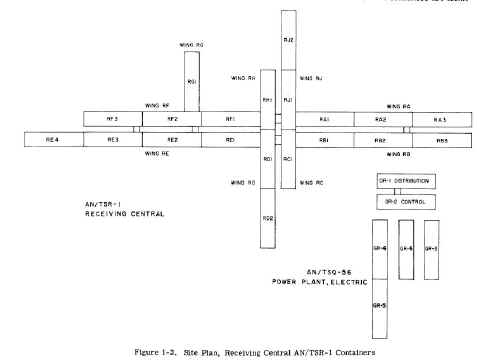 |
RA1 -HICOM/ASC
RA2 - Off-Line and Crypto Repair
RA3 - Special Receiver
RB1 - Classified Control
RB2 - Crypto
RB3 - Crypto |
RC1 - Multi- Channel Crypto
RD1 - Electronic Repair
RD2 - Supply Container
RE1 - Unclassified Control
RE2 - HICOM Voice & Microwave
RE3 - Receivers
RE4 - Receivers and RF Patching |
RF1 - Message Center
RF2 - C/W Ship/Shore
RF3 - Air/Ground
RG1 - Communication Off ice
RH1 - TTY Repair
RJ1 - NTX Receive
RJ2 - NTX Send Electric Power System |
GR1 - Power Distribution
GR2 -Power Control
GR3 and GR6- Generators
GR4 and GR5 -No Break Power |
AN/TST-2 Transmitter Site
 |
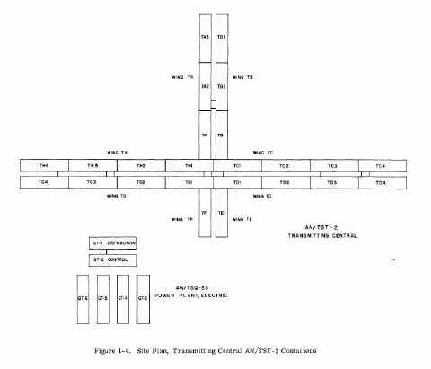 |
TA1 - Transmitter Set 10 KW
TA2 - Transmitter Set 10 KW
TB2 - Transmitter Set 10 KW
TB3 - Transmitter Set 10 KW
TC4 - Transmitter Set 10 KW
TD4 - Transmitter Set 10 KW
TG2 - Transmitter Set 10 KW
TA3 - Transmitter Set 1 KW and 10 KW |
TB1 - Transmitter Set 40 KW
TC2 - Transmitter Set 40 KW
TC3 - Transmitter Set 40 KW
TD2 - Transmitter Set 40 KW
TD3 - Transmitter Set 40 KW
TG3 - Transmitter Set 40 KW
TH1 - Transmitter Set 40 KW |
TC1 - Transmitter Control
TD1 - RF Distribution
TE1 - Transmitter Set -Low Frequency
TF1 - Work Shop
TG1 - RF Distribution
TH2 - Transmitter Set 40 KW
TH3 -Transmitter Set 200 KW |
TH4 -Transmitter Set 50 KW
TG4 - Low Pass Filter
Helix Container
GT1- Power Distribution
GT2-Power Control
GT3, GT4, GT5 and GT6 Generators
Mobile Workshop Trailer |
Operational Capability
RELAY FACILITIES.
a. 48-line torn-tape NTX class relay with 18 receive page-copy monitors.
b. 18-line torn-tape HICOM/ASC relay with 12 receive page-copy monitors.
RECEIVERS.
a. Nine synthesized SSB diversity receivers with pro visions for installing additional units.
b. One synthesized SSB non-diversity receiver.
c. Thirteen diversity RATT receiver/converter bays, one equipped for low-frequency RATT operation.
d. Three monitor-receiver bays each with 5 receivers and 1 converter.
e. Six CW/Ship-shore send/receive circuits and one low-frequency distress circuit.
f. Six HICOM and point-to-point voice terminals.
g. Nine air/ground, search and rescue circuits; 6 high-frequency and 3 VHF/UHF.
CRYPTOGRAPHIC FACILITIES.
a. Sixty-four TSEC/KW-26C send/receive
b. Four TSEC/KW-22 send/receive
c. Three TSEC/KW-22 send/receive bays.
d. Two TSEC/HW-10/19.
e. Two AN/GGA-1.
In addition, space has been provided for four TSEC/ KG- 14 and three TSEC/KW- 7 and associated equipments.
TERMINAL EQUIPMENT.
a. Eight 16- channel full-duplex tone-diversity telegraph units.
b. Four 16- channel non-diversity full-duplex tone telegraph units.
c. Three sets 8-narrow 4-wideband send non-diversity CCL tone telegraph units from the Receiving Central to the Transmitting Central.
d. One set 8-narrow 4-wideband send non-diversity CCL tone telegraph unit from the Transmitting Central to the Receiving Central.
e. One 60-send and 24-receive channel CCL voice terminal at the Receiving Central (expandable to 60-send and 60-receive channels).
f. One 24-send and 60-receive channel CCL voice terminal at the Transmitting
Central (expandable to 60-send and 60-receive channels).
g. Sixteen 3-to-6-kc multiplexer units at the Transmitting Central.
h. Sixteen 6-to-3-kc demultiplexer units at the Receiving Central.
TRANSMITTERS.
a. Ten 1-kilowatt (PEP) synthesized SSB Transmitters.
b. Thirty-seven 10-kilowatt (PEP) synthesized SSB transmitters.
c. Sixteen 40-kilowatt (PEP) synthesized SSB transmitters.
d. One 200-kilowatt (PEP) synthesized SSB transmitter.
e. Two 2-kilowatt low-frequency transmitters.
f. One 15-kilowatt low-frequency transmitter.
g. One 50-kilowatt low-frequency transmitter.
h. 80-line transmitting antenna patching facility equipped with inter-patch panel trunking.
i. Remote RF monitoring and remote visual and audible alarm facilities at
a transmitter control center for all transmitters.
CIRCUIT-PROGRAMMING FACILITIES.
a. The following main frame circuit-programming facilities are provided:
1. 5760-pair BLACK program board.
2. 2880-pair RED program board.
b. The following intermediate distribution frame circuit-programming facilities
are provided:
1. 1440-pair RECEIVERS audio program board.
2. 1440-pair TRANSMITTERS audio program board.
3. 1440-pair TRANSMITTERS D-C program board.
c. The following special distribution frame circuit- programming facilities are provided:
1. 360-pair HICOM voice program board.
2. 216-pair audio and 108-pair D-C special receiver RED program board.
3. 216-pair audio and 108-pair D-C special receiver BLACK program board.
PATCHING FACILITIES.
a. 384-send / 384-receive normal-through BLACK circuit monitor patchboard with 192-miscellaneous
circuit appearances.
b. 144-send / 144-receive normal- through circuit monitor patchboard with remote and alarm indication each circuit, and 96-miscellaneous
circuit appearances.
c. 24-line send / 24-line receive normal-through HICOM Voice circuit monitor patchboard with
48 miscellaneous circuit appearances.
d. 96-line send / 96-line receive normal-through Receivers monitor patchboard with
48 miscellaneous circuit appearances.
e. 120-line send / l20-line receive normal-through transmitter circuit monitor patchboard with
48-miscellaneous circuit appearances.
f. 96-line transmitters DC circuit monitor patch board with 144-miscellaneous DC circuit appearances.
g. Two special receiver monitor patchboards, one RED and one BLACK, each consisting of 24-line audio and 24-line DC circuits with 24-miscellaneous DC
circuit appearances.
WEATHER FACILITIES.
Four send/receive weather positions.
MULTIPLEX FACILITIES
Three AN/UGC-1A time division TTY multiplex units.
FACSIMILE.
a. One facsimile transceiver with associated keyer.
b. One facsimile continuous page printer with associated converter.
PRIMARY POWER FACILITIES.
208-volt, 60-cycle, 3-phase, 4-wire primary power is supplied at each site, with power capability as follows:
a. Receiving Central. 2010 kilowatts standard power system and 400-kilowatts no-break power
sys tem.
b. Transmitting Central. 4020 kilowatts standard.
REPAIR FACILITIES.
a. Cryptographic repair area.
b. Teletype repair shop.
c. Two electronic repair shops, one at each site.
d. One mobile workshop trailer.
SUPPLY FACILITIES.
One and one-half containers at receiver site and one-half container at transmitter site.
RECEIVER SITE ANTENNA FACILITIES.
a. Six Rotatable Log-Periodic and two fixed Log-Periodic.
b. Three Conical Monopole.
c. Eleven Vertical Folded Doublet.
d. Two Dual- Nested Rhombics.
e. Two Single Rhombic.
f. Two Low- Frequency Long-Wire.
TRANSMITTER SITE ANTENNA FACILITIES
a. Fourteen Vertical Folded Doublet.
b. Twenty-nine Conical Monopole (includes one high-power CM).
c. Ten Rotatable Log Periodic.
d. Six Dual-Nested Rhombics.
e. Two Single Rhombic.
f. Two Low- Frequency Long-Wire.
g. One Low-Frequency 630-foot Pan Polar.
h. One Low-Frequency 359-foot Pan Polar.
USMC AN/TSC-95 - HF Communications System
The Communications System, AN/TSC-95 is intended to provide the Force commander with the means to effect a Fleet Marine
Force (FMF) mobile command termination with a naval communications station. The AN/TSC-95 has the capability of
terminating two high frequency communication links operating in a full-duplex mode. These links can be either teletype, secure
teletype, voice, or any combination thereof.
The mission of the AN/TSC-95 is to provide the landing force with an independent means of
exchanging operational and administrative traffic between the landing force and commands outside the objective area. In
particular, it will provide access to the worldwide Defense Communication System (DCS) through a naval communications
station (NAVCOMMSTA) termination. In a Marine amphibious force operation, it is planned to assign four AN/TSC-95's to the
communications support company (CSC) of each of the communications' battalions. One AN/TSC-95 would be provided by
the CSC to the senior Marine air-ground task force (MAGTF) commander for effecting an FMF mobile command net termination
upon establishment of the landing force command ashore. The remaining AN/TSC-95's would provide similar long-distance
terminations for division, wing, and service support group headquarters as required.
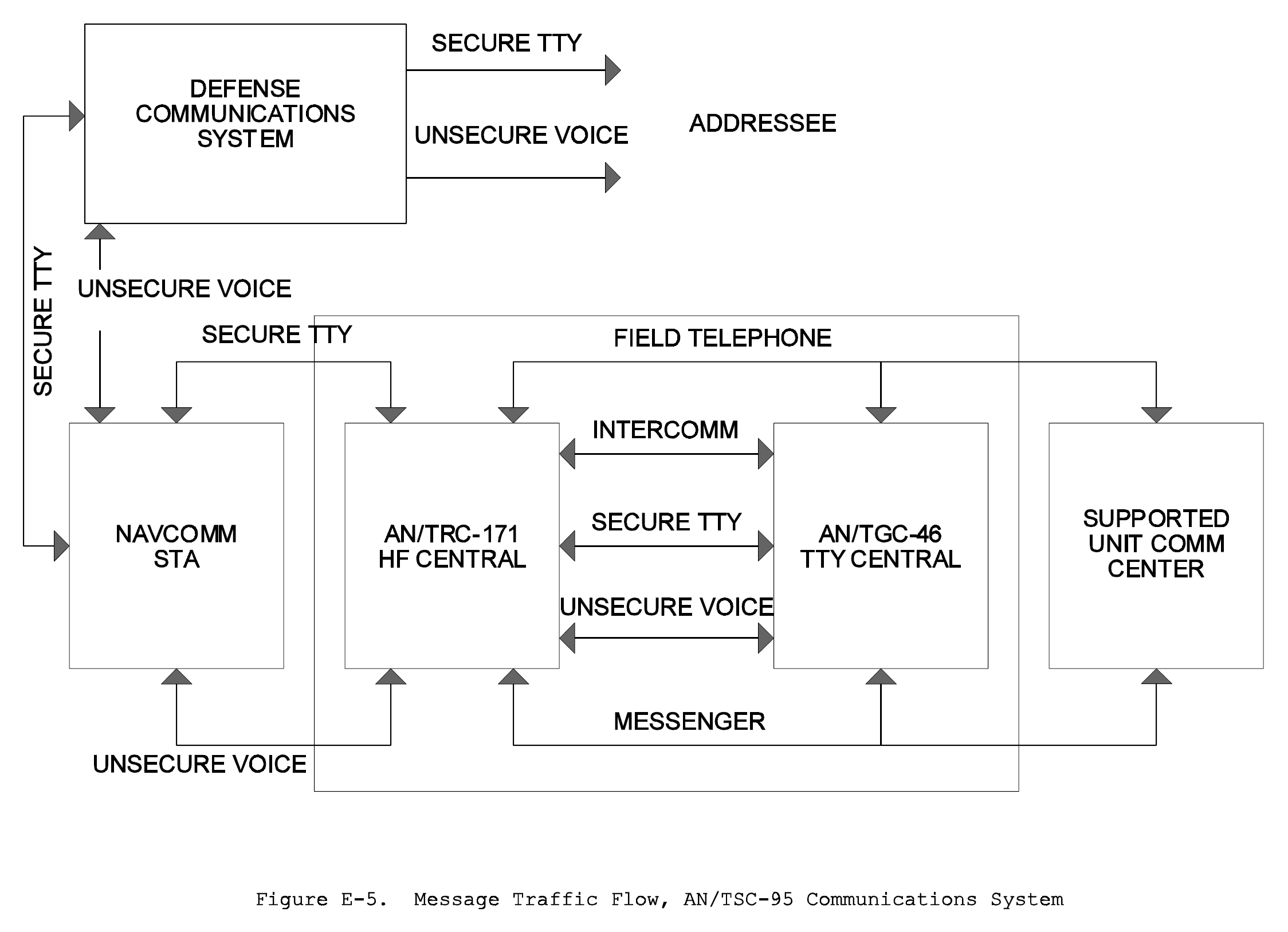
The AN/TSC-95 consists of a High Frequency Communications Central, AN/TRC-171, and a
Teletypewriter Central, AN/TGC-46, together with necessary antennas and ancillary equipment. The system is housed in two
S-280 shelters, which are helicopter transportable or which can be mounted on a standard USMC 5-ton truck. The system does not
require a dedicated prime mover. It must be displaced by Helo or truck prior to operation. Two 15-kilowatt (kW), 60-hertz
(hz), generators not supplied as part of the AN/TSC-95, are required to power the system. The AN/TRC-171 and AN/TGC-46 are
capable of being operated as independent systems. When operated alone, the AN/TRC-171 is capable of establishing the
high frequency communication links in the voice mode only, since it contains no record terminal equipment. The AN/TGC-46
can be operated as an independent teletypewriter terminal; however, transmission paths must be provided by other means.
The AN/TSC-95 system provides for reliable single sideband
radio-teletype or voice communications with a designed, designated NAVCOMSTA. CW
transmission and reception type communications are also available. The system
has been designed with maximum patching flexibility and can be operated in
various modes, thus permitting the selection of the most advantageous mode for
each tactical deployment. The system has three basic modes of operation: FSK,
Voice Frequency Carrier Teletype (VFCT), or voice. These three basic modes
provide the seven operating mode options that may be employed separately or in
combination as listed in Table E-10.
AN/TRC-171 Communications Van
 |
AN/TSC-95 Message Flow
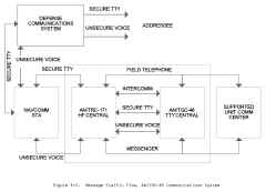
|
AN/TSC-95 Operating Modes
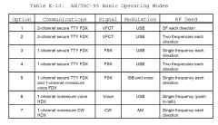 |
- TM-5815-14/1 Installation, Operation, and Maintenance Manual
Teletypewriter Central, AN/TGC-46
- TM-5895-14/1 Operation, Maintenance, and Installation Instructions,
Communication Central AN/TRC-171
- TM-08059A-12 Operation, Maintenance, and Installation Instructions
Communication Set, AN/TSC-95
- 4 ea. HF Transmit antenna
- 4 ea. HF Receive Antenna
- 2 ea. URT-23 transmitters (RF Van)
- 3 ea. R-1051 receivers (RF Van)
- 1 ea. AN/UCC-1 VFCT multiplexer (TTY Van)
- 4 ea. KW-7 crypto (TTY Van)
- misc TTY equipment (TTY Van)
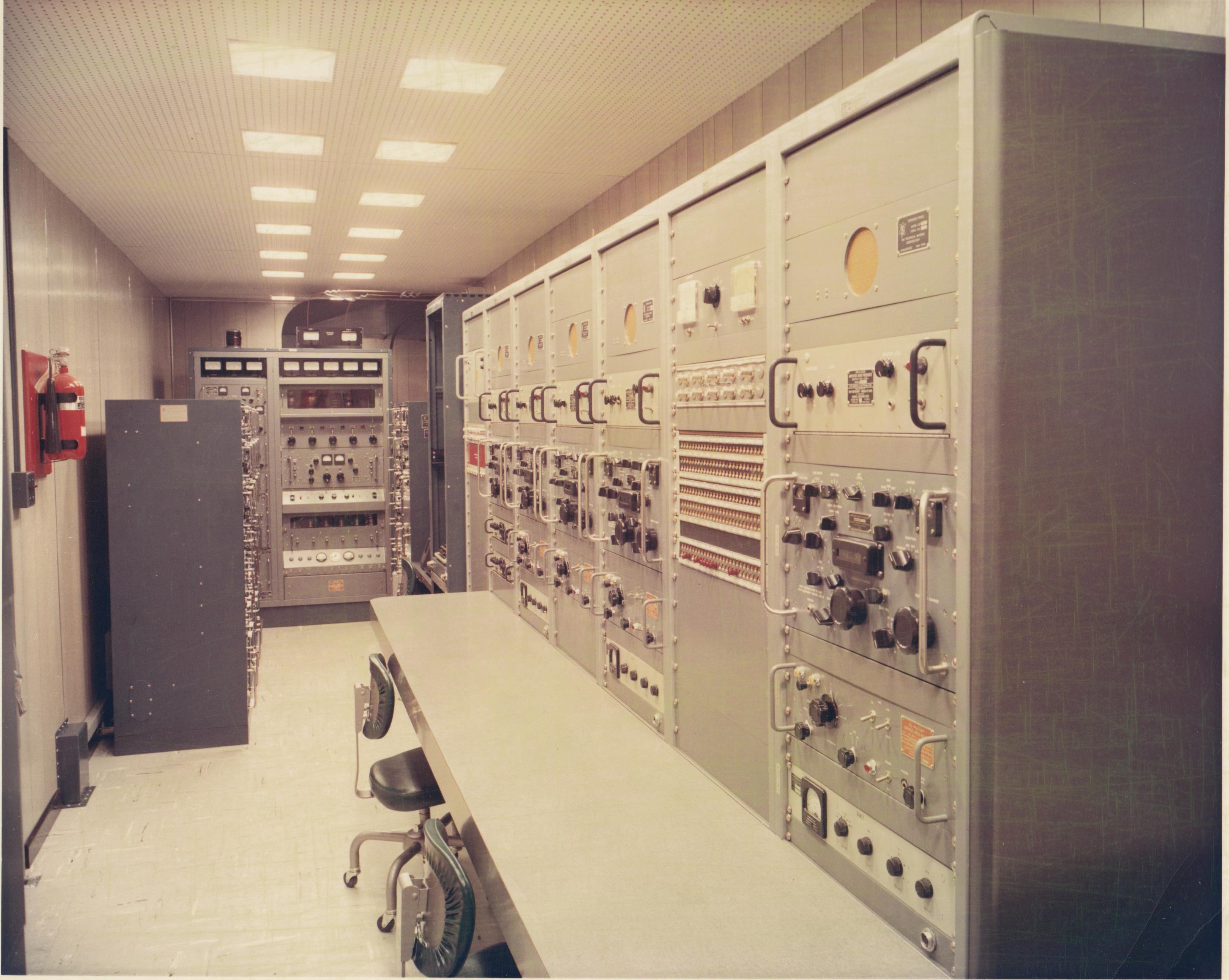
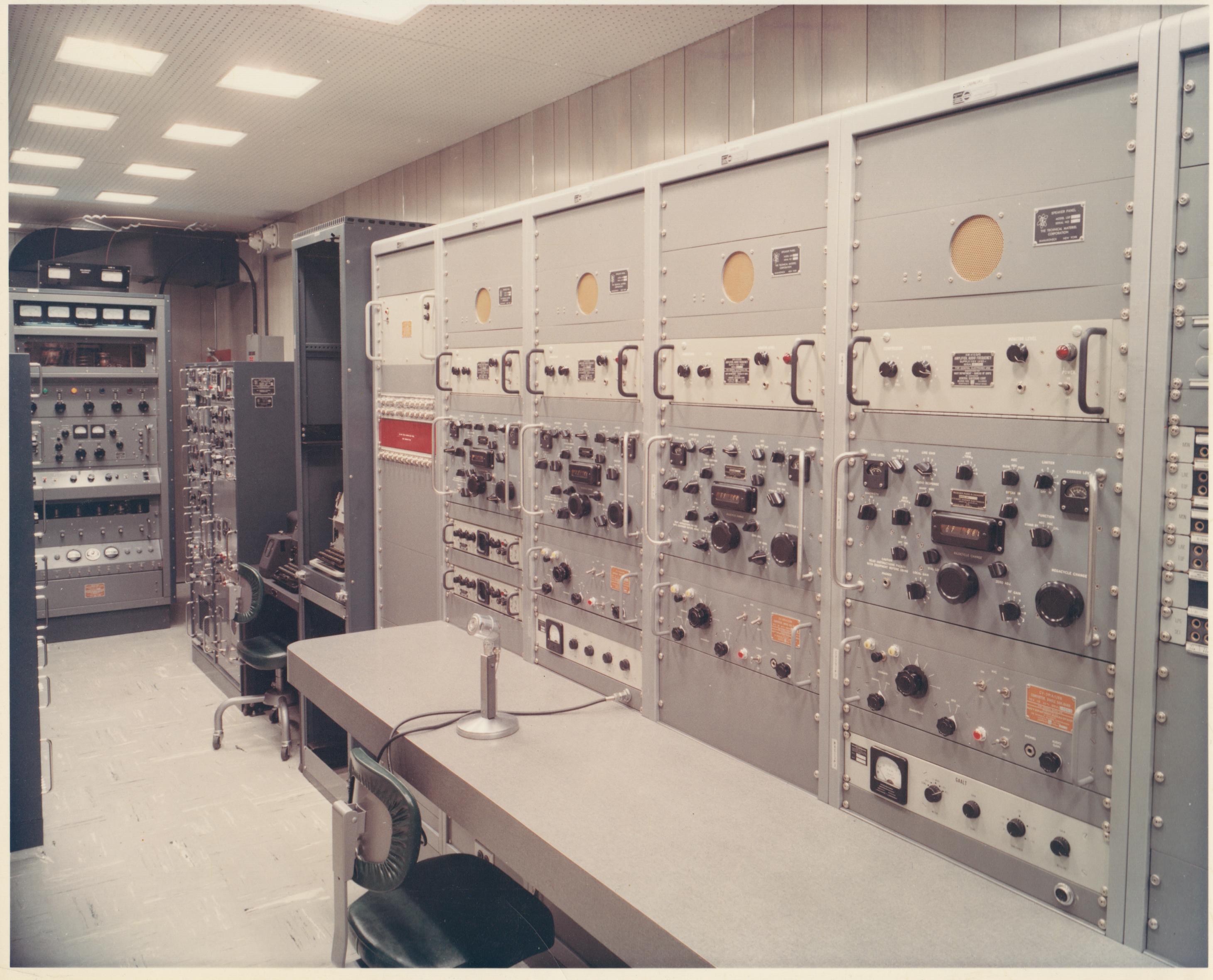
Mystery Van Commcenter - manufactured by TMC (Project Foxtrot)
Navy ID tags on most equipment - AN/FRT-39 xmtr (GPT-10K), AN/FRT-70 xmtr
(synthesized SBT-1K), CV-591A/URR SSB converters, AM-413D/G audio amps,
AN/URT-17 FSK converters, CU-168/URR multicoupler -
I can't tell what is on the left side - I think 2 more SBT-1Ks?
Interestingly, not Model 28 TTY gear, but a M19 and M15????
Please send me e-mail with any
photos, additional info, etc.
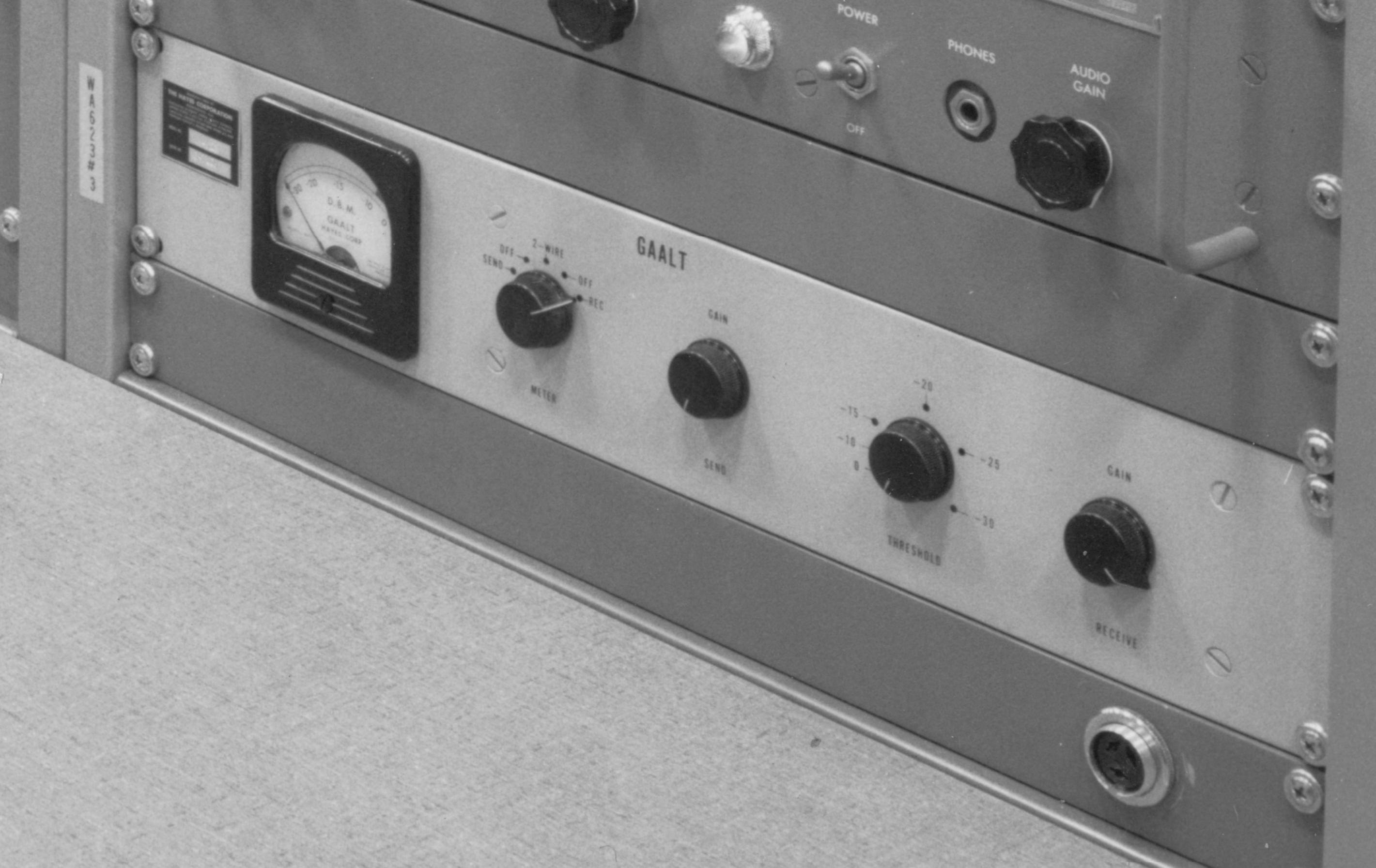
the mystery item at the bottom of the rcvr racks say "The Hayes
Corporation" and "GAALT" - also labeled WA-623 rcvr on the rack
and audio patch panel.

ARMY ONLY?
AN/TSC-16 - air transportable communications unit
- 2 vans plus tractors & generators
- airlifted via 3 C-124's
Capabilities
- 16 channel VFCT
- Fax
- 2 channel voice
Receiver-Control Van
- AN/FRR-41 HF Diversity Receiver (two R-390A/URR + two CV-157/URR)
- AN/FRR-40 HF Receiver (R-390A/URR + CV-157/URR)
- AN/TSC-16 16 channel multiplex unit
- TTY equipment
- FAX equipment
- UHF inter-site transceiver
Transmitter Van
- 10 kw AN/FRT-39 HF transmitter
- UHF inter-site transceiver