"The Navy's Radio Teletype Systems Afloat"
- BuShips Journal April 1956
"The Navy's Radio Teletype Systems Afloat"
By Joseph J. Fisher, Electronics Installation and Maintenance Engineering Branch,
and Victor L. Kebler. Electronics Publications Section, Bureau of Ships
In the history of naval progress, communications play an increasingly important role. There was a time
when visual devices were the only means of communication between ships and between a ship and the
shore.
The semaphore, the flag-hoist, and the flashing light were sight communications, nothing more. When
these were the only means of communication for a ship, out of sight meant out of communication. A ship
alone on the high sea was isolated from the rest of the world.
Radio Communication
Then came radio communications—first, the telegraph key with the dot-and-dash code that is now
known as CW; and later, voice radio communications. Now, a ship at sea can be in communication with other
ships and the shore at all times. Being out of sight no longer means out of communication.
Following the discovery of the principles of radio, the use of naval communications increased in volume
as rapidly as the number of circuits and the efficiency of equipment permitted. Radio systems soon were
overloaded.
To lighten the load of CW and voice radio communications, the Navy needed a new means of
dependable, rapid radio communication. The answer to the problem was "radio Teletype." The basic equipment
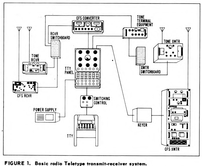
for a shipboard radio Teletype installation is shown in figure 1.
The Navy uses two radio Teletype systems afloat. One, the tone modulated system for short-range
operations, is similar to the familiar AM radio. The other, the carrier frequency-shift system for long-range
operations, is similar to the standard FM radio. The two systems are shown integrated in figure 1. This
article describes the general principles that apply to the operation of radio Teletype equipment.
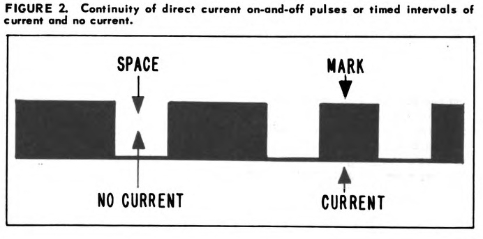
The teleprinter sends out a continuity of direct current on-and-off pulses (or timed intervals of current
and no current, as in figure 2). An "on" or "current" interval is called a "mark" or marking impulse. An
"off" or "no-current" interval is a "space" or spacing impulse.
The marks and spaces are generated in various code groups; that is, one group is produced for each
character or function being transmitted. A group has five units.
Knowledge of the specific groupings is incidental to an understanding of the operation of the radio
Teletype system. The important thing to know is that the succession of direct current "marks" and
"spaces" in fixed-timed intervals conveys both intelligence and synchronization
from one printer to another.
When two teleprinters are wire-connected, the exchange of communications between them is simple.
But when the teleprinters are not joined by wire, the operation is more complex. Direct-current mark and
space intervals cannot be sent through the air.
The gap between the teleprinters must be bridged by radio. To bridge the gap, a radio transmitter and
receiver are needed. The radio transmitter produces a radiofrequency carrier wave to carry the mark and
space intelligence. Also, a device such as a keyer is needed to change the direct current pulses from the
teleprinter into corresponding mark and space modulation for the carrier wave in the transmitter. The radio
receiver and a converter are required to change the radiofrequency signal back to direct-current pulses.
The differences in the Navy's two radio Teletype systems, as well as their names,
are derived from the
nature of the carrier wave used—the tone modulated carrier wave for short-range work and the carrier frequency shift system for long-range
work.
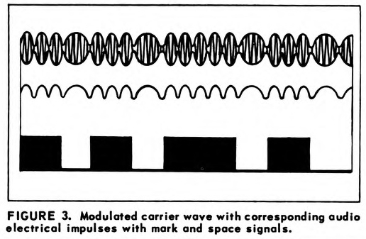
Figure 3 delineates a modulated carrier wave with audio tone impulses impressed on the
radio frequency carrier wave, with corresponding direct-current mark and space signals.
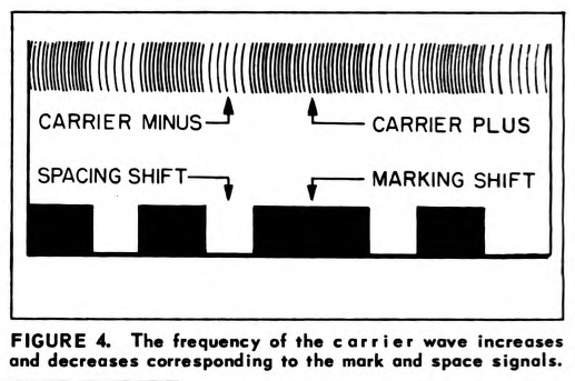
Figure 4 shows a carrier frequency shift wave which increases and decreases to denote mark and space
direct-current impulses.
In the operations shown in figures 4 and 5, the direct-current Teletype signal that can travel only by
wire becomes, through the medium of a tone terminal or keyer unit, either a tone modulated signal or a carrier
frequency shift signal for radio carrier wave transmission.
Short-Range System
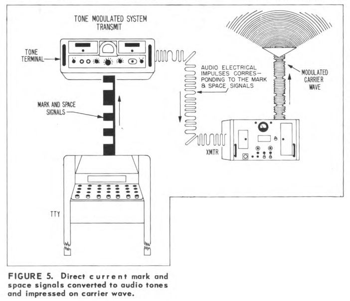
To transmit messages by the short-range system, a teleprinter, a tone terminal, and a transmitter are
used. The teleprinter sends out a direct-current signal. The signal is changed to audio tones in the tone
terminal. The transmitter impresses the audio tones on the carrier and sends out a tone modulated carrier
wave (figure 5).
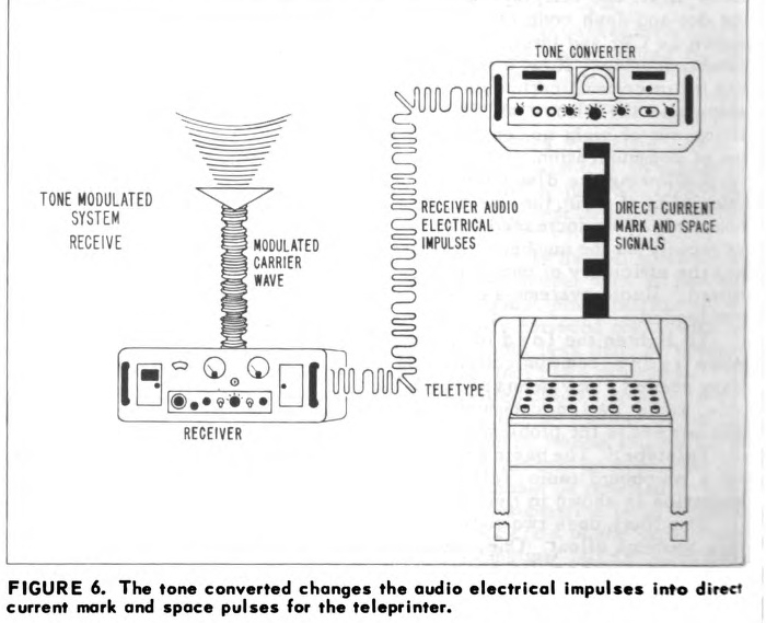
To receive messages with the short-range system, a radio receiver, a tone converter, and a teleprinter
are needed. The tone modulated carrier wave enters the receiver which extracts the signal intelligence and
sends the audio tones to the tone converter. The converter changes the audio tones into direct-current
mark and space pulses for the teleprinter (figure 6).
In practice the same tone terminal is used for the receiving and the sending circuits since it contains
both a transmit "keyer" unit and a receiver "converter" unit.
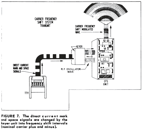
At the transmitting end of the long-range system are a teleprinter,
a transmitter, and a frequency shift keyer unit which is built into the newer transmitters. In some older
systems the keyer unit is a separate piece of equipment. When the teleprinter is operated, the direct-current
teleprinter mark and space signals are changed by the keyer unit into frequency shift intervals.
The frequency shift intervals are transmitted as carrier frequency shift signals (figure 7).
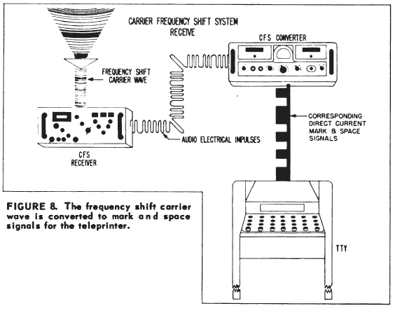
On the receiving side of the long-range system, are a receiver, a frequency shift converter, and a teleprinter. When the carrier frequency
shift signal enters the receiver, it is detected and changed into a corresponding frequency shifted audio
signal. The audio output of the receiver is fed to the converter, which changes the frequency shifted audio
signal into the direct-current mark and space Teletype signals (figure 8).
When the carrier frequency shift system is combined with the tone modulated system, several more
pieces of equipment are needed - a Teletype panel, a power supply, a switching control, a transmitter
switchboard, and a receiver switchboard.
The Teletype panel is capable of handling six channels, or "loops." The power supply furnishes the direct "looping" current for all Teletype direct-current signals. The
switching control, located at the teleprinter, is used to select the system desired. The transmitter
switchboard and the receiver switchboard are used to integrate the radio Teletype systems with other
communication systems on board ship. Integration of the various systems results in a compact and flexible
installation.
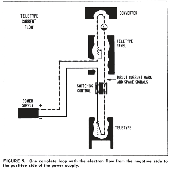
The Teletype panel interconnects the teleprinter with all the electron flow from the negative side to
different radio keyers and converters as shown in figure 1. The Teletype panel controls the direct "looping"
current channels. Figure 9 is a diagram of one Teletype loop.
When the Teletype system is in operation, the electron current - which flows from negative to
positive - flows from the negative side of the power supply through the Teletype panel, through the teleprinter,
back through the Teletype panel, into a converter or keyer unit, through the Teletype panel a third
time, and from there on to the positive side of the power supply.
When the direct-current loop is alternately opened and closed by the teleprinter or one of the converters,
the result is current and no-current, or mark and space intervals that characterize the direct-current
Teletype signal. This is what happens in all of the direct-current loops in both of the Navy's radio Teletype
systems.
The looping current is controlled by a rheostat in the Teletype panel. A common power supply is used for
all Teletype panels in shipboard installations. In the front panel of the cabinet each of the six channels, or
circuits, has a pair of looping jacks, a set jack, and an additional jack for miscellaneous Teletype
requirements.
The numerous terminal and patching connections in the Teletype panel provide many different
circuit possibilities. For instance, a keyer or converter circuit that terminates in channel 2 can be
patched across to channel 5 to connect with Teletype equipment that ends there. A dummy plug is used to short
out the unwanted portion of the circuit.
In both the tone-modulated system and the carrier frequency shift system, all Teletype signals pass
through the Teletype panel that controls the looping current in all the circuits. The Teletype panel
integrates the tone modulated and the carrier frequency shift systems. It provides every possible radio
Teletype interconnection available on board ship. This operational flexibility gives maximum efficiency with
the fewest circuits and the least amount of equipment in the Navy's compact radio Teletype systems
afloat.