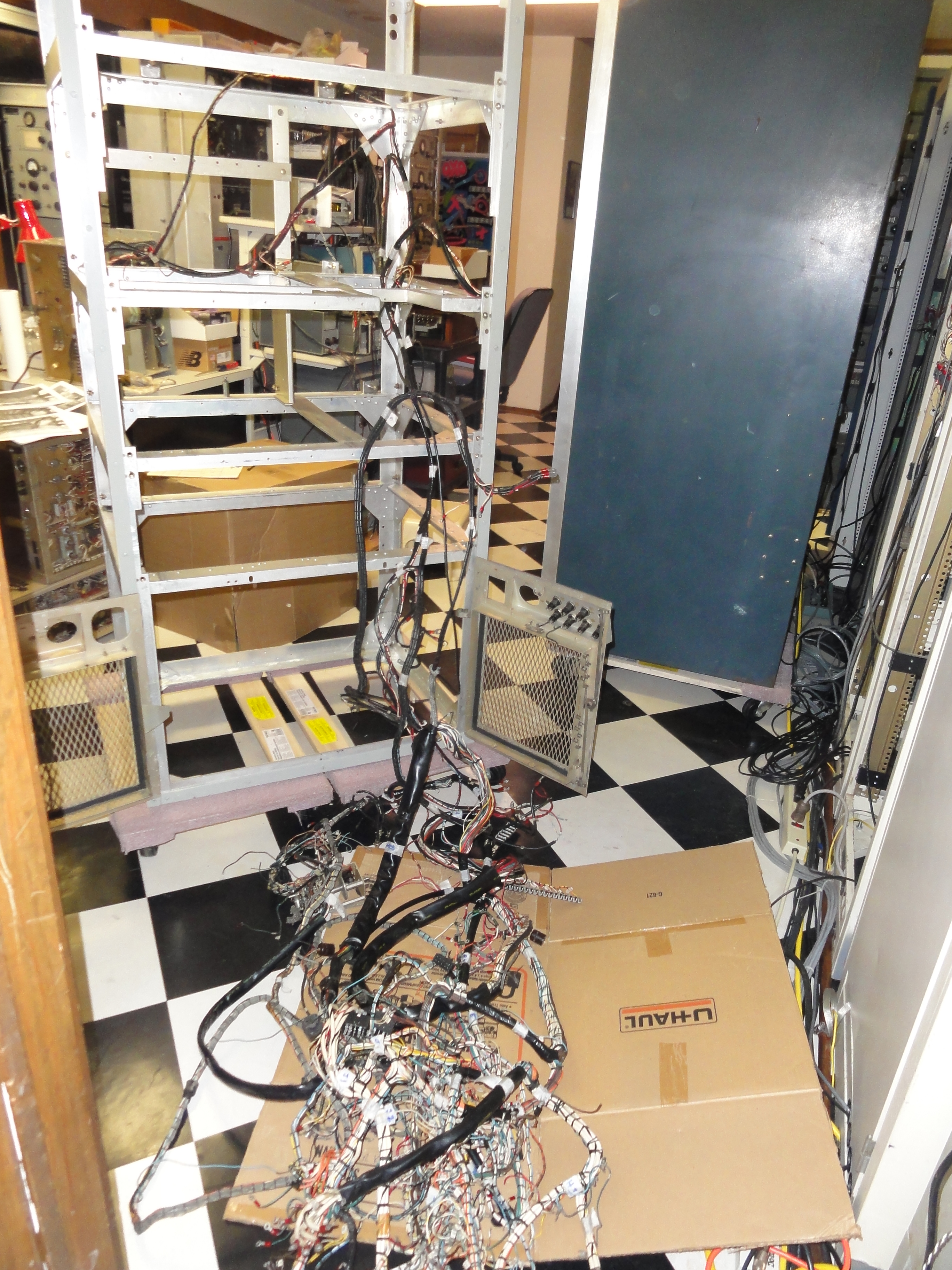
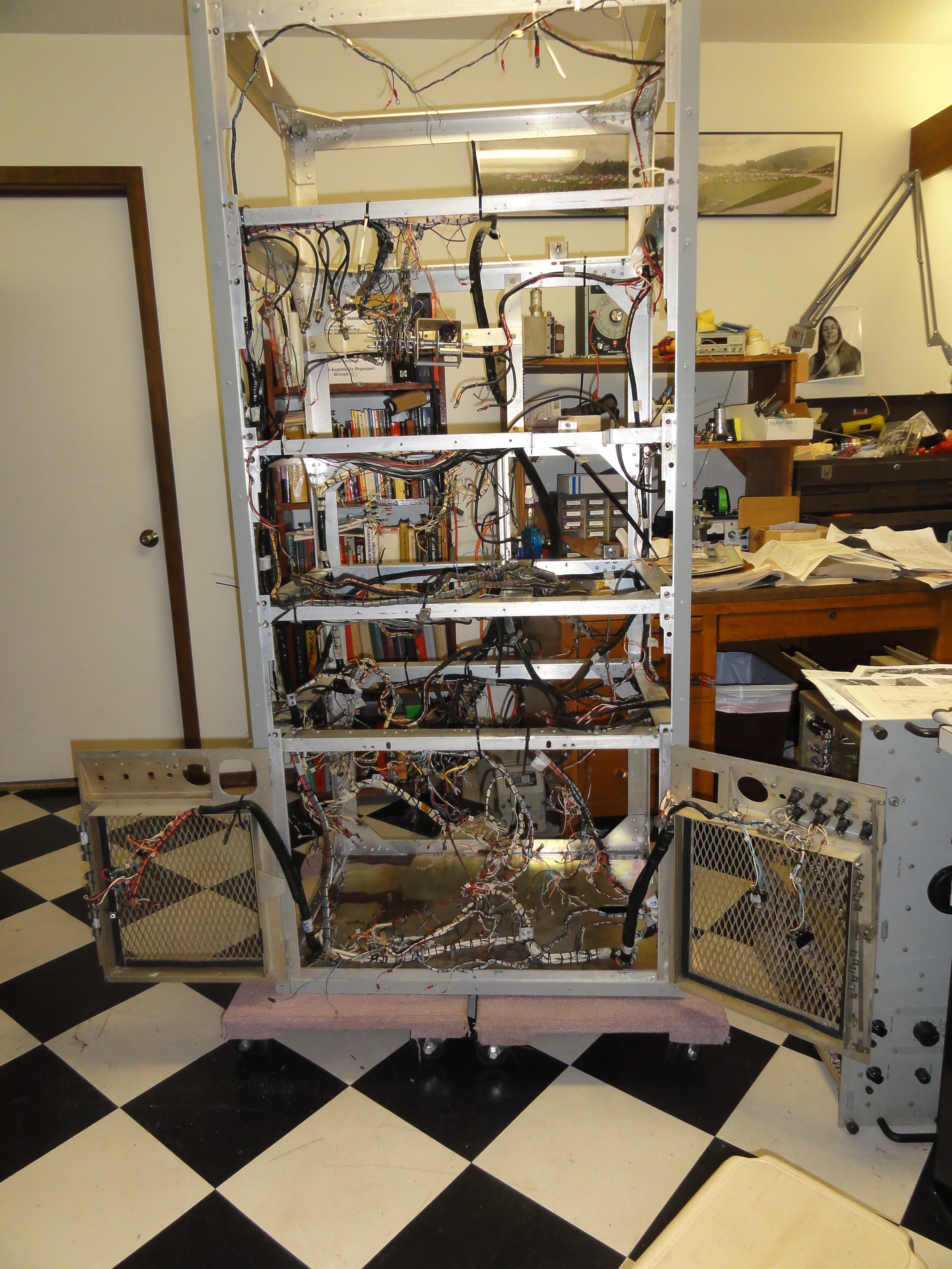
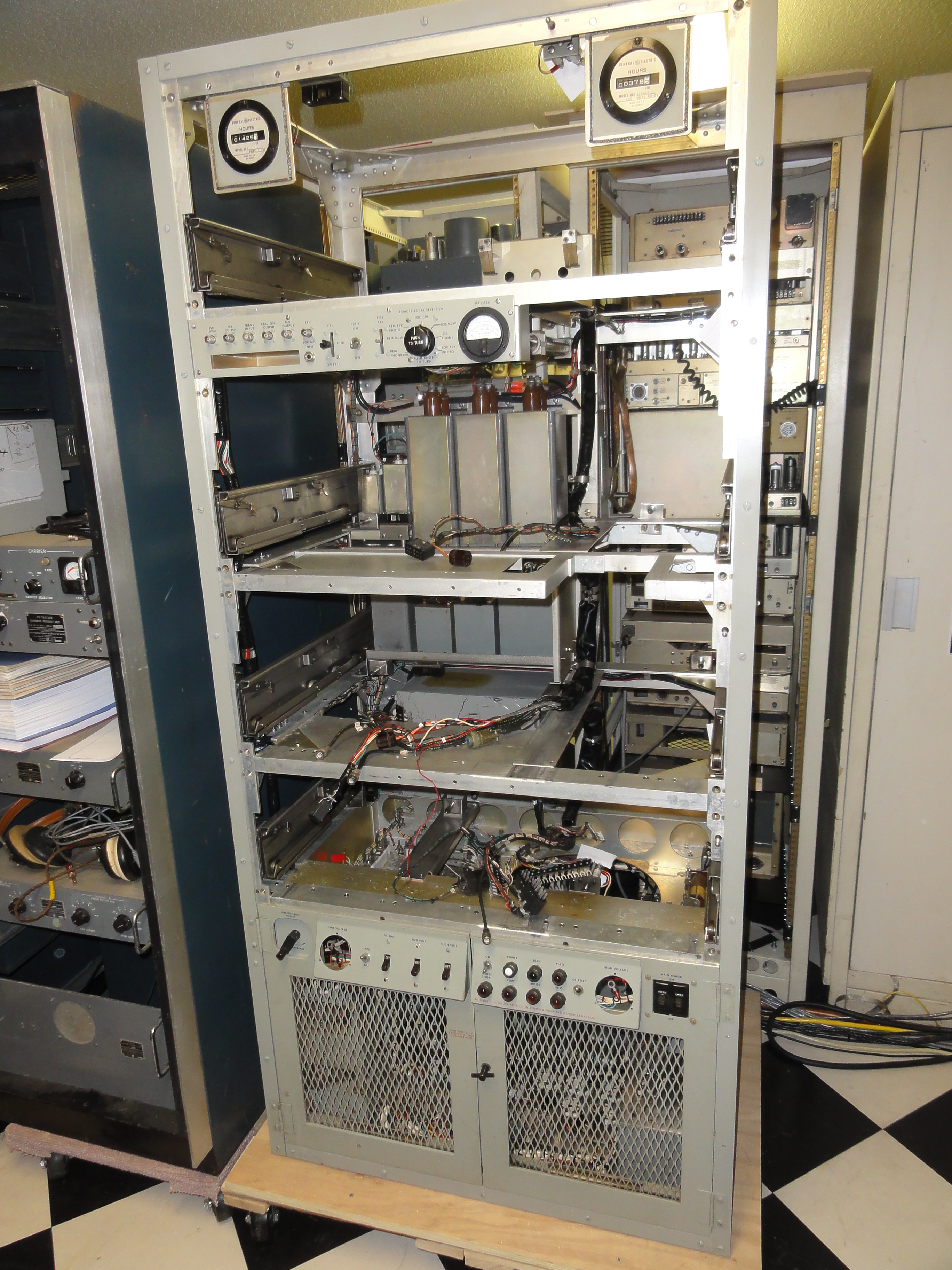
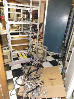
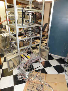
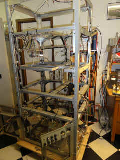
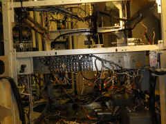
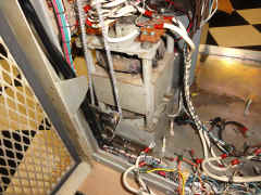
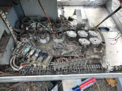
The puzzle begins - can I ever get it back together & working
?????
|
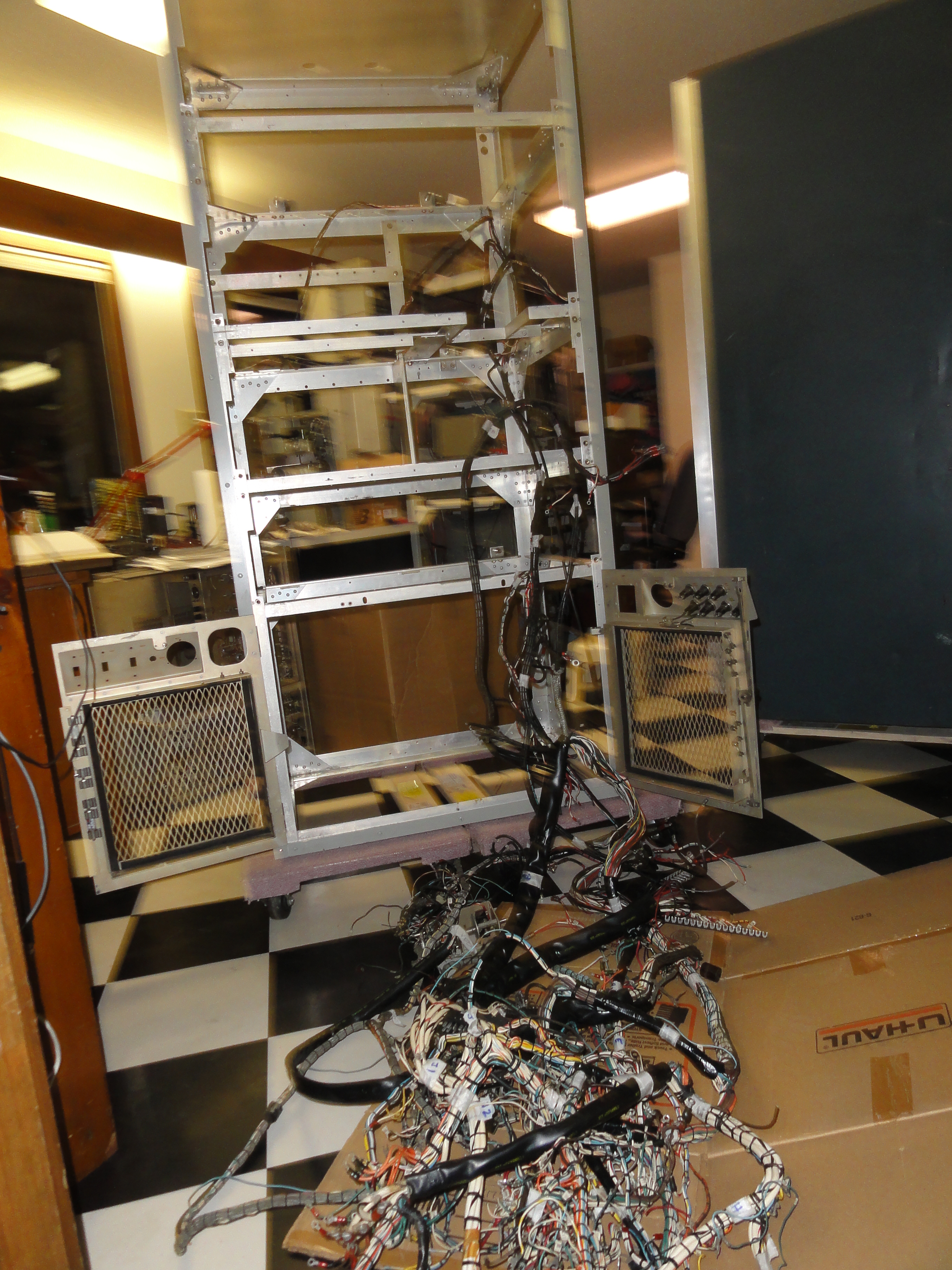
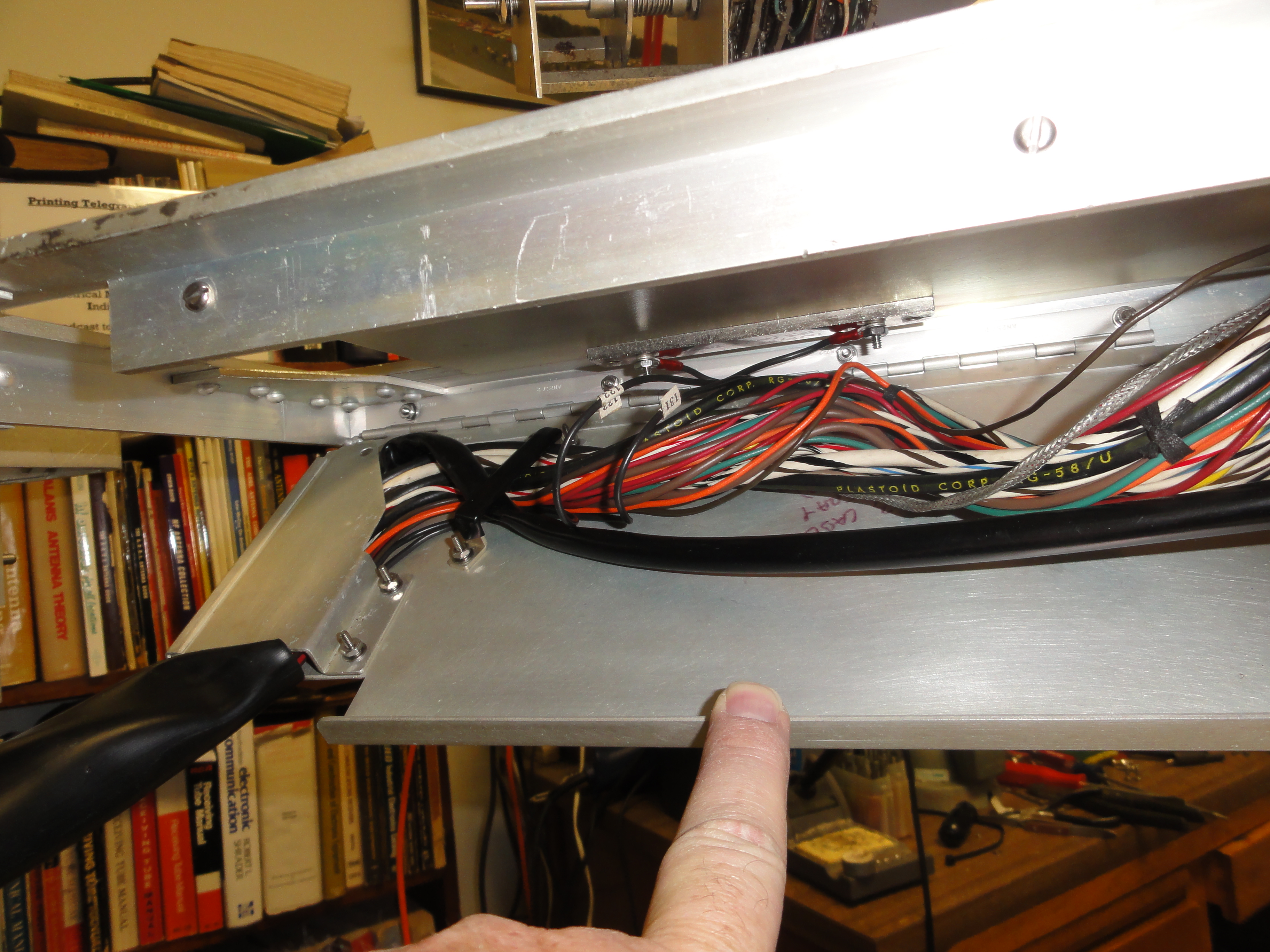
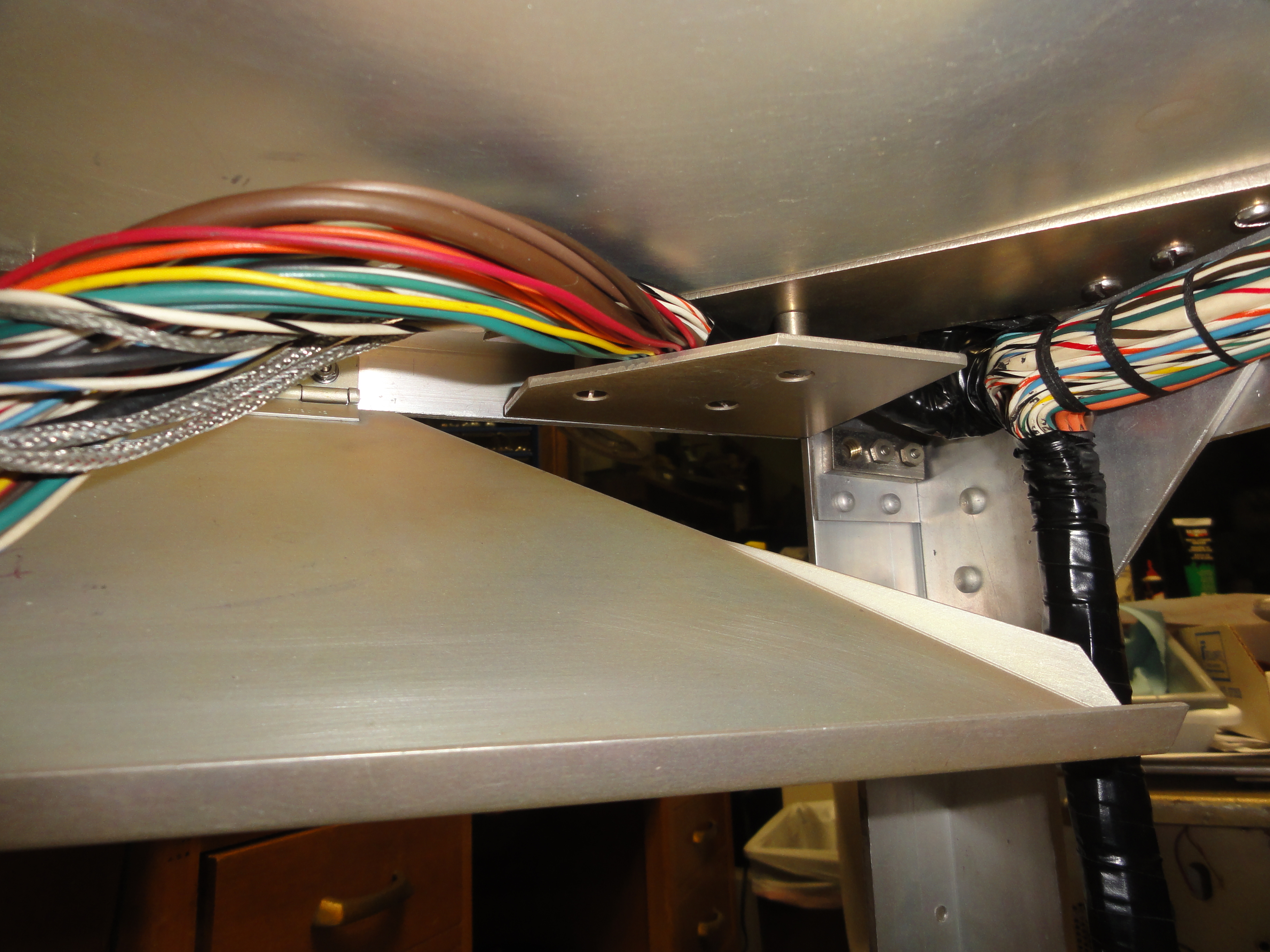
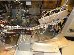
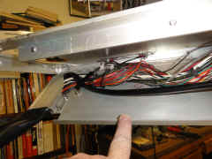
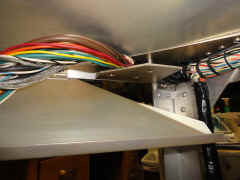
Drag the harness to the chassis and start
![DSC01522.JPG (3512180 bytes)](frt17/frt17-4/DSC01522_small.JPG) |
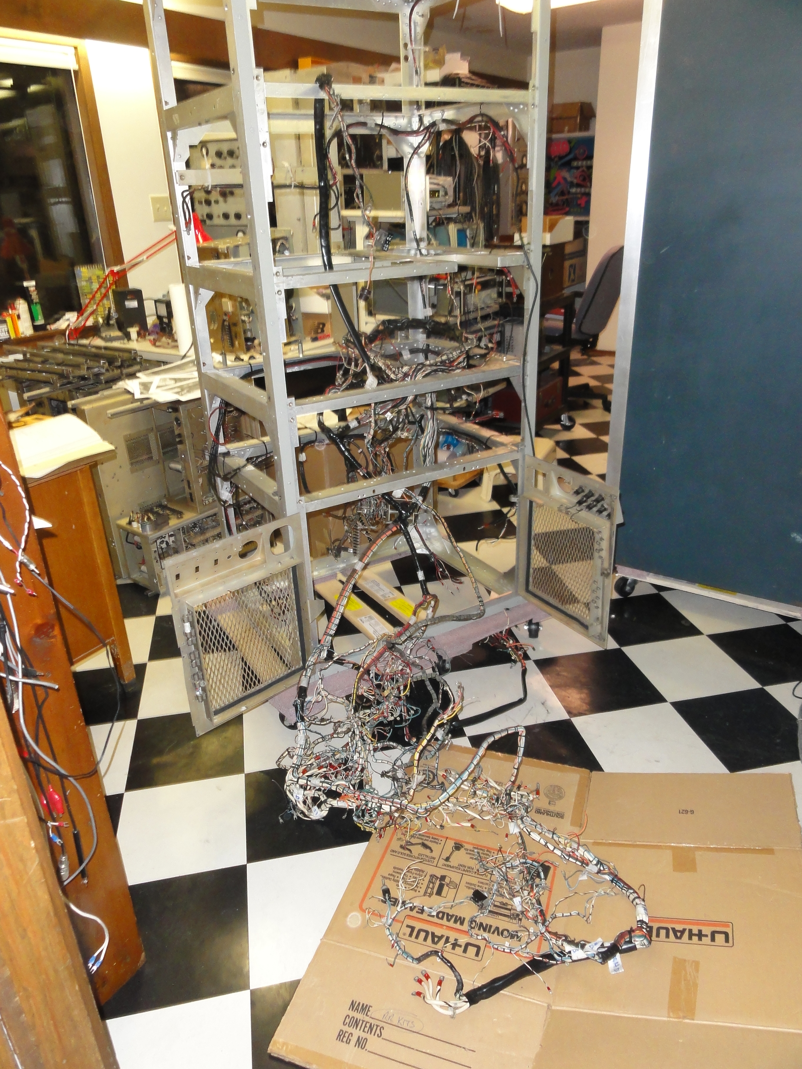
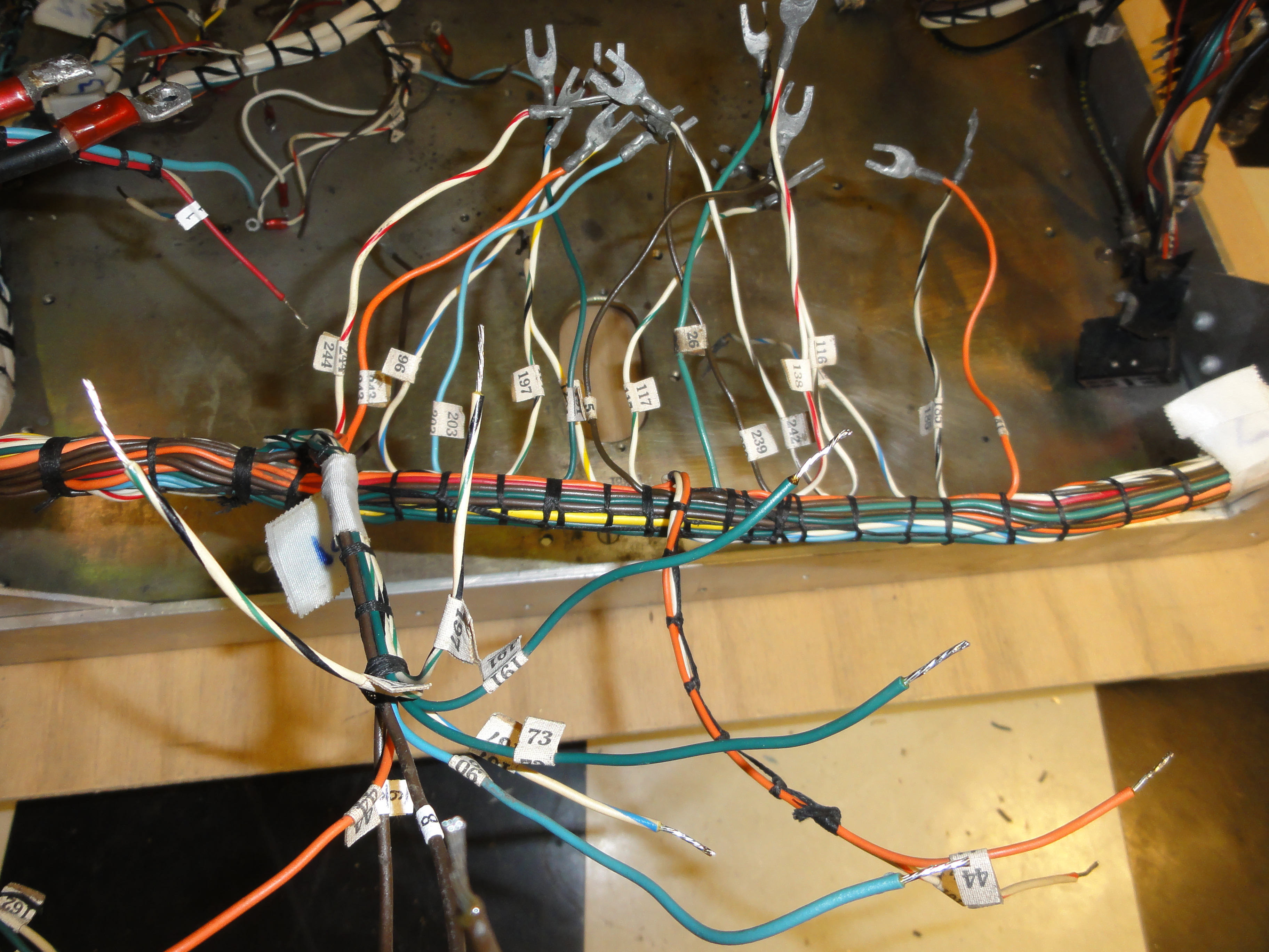
A few false starts and I figured out a plan for threading it all
together
![DSC01524.JPG (3548741 bytes)](frt17/frt17-4/DSC01524_small.JPG) |
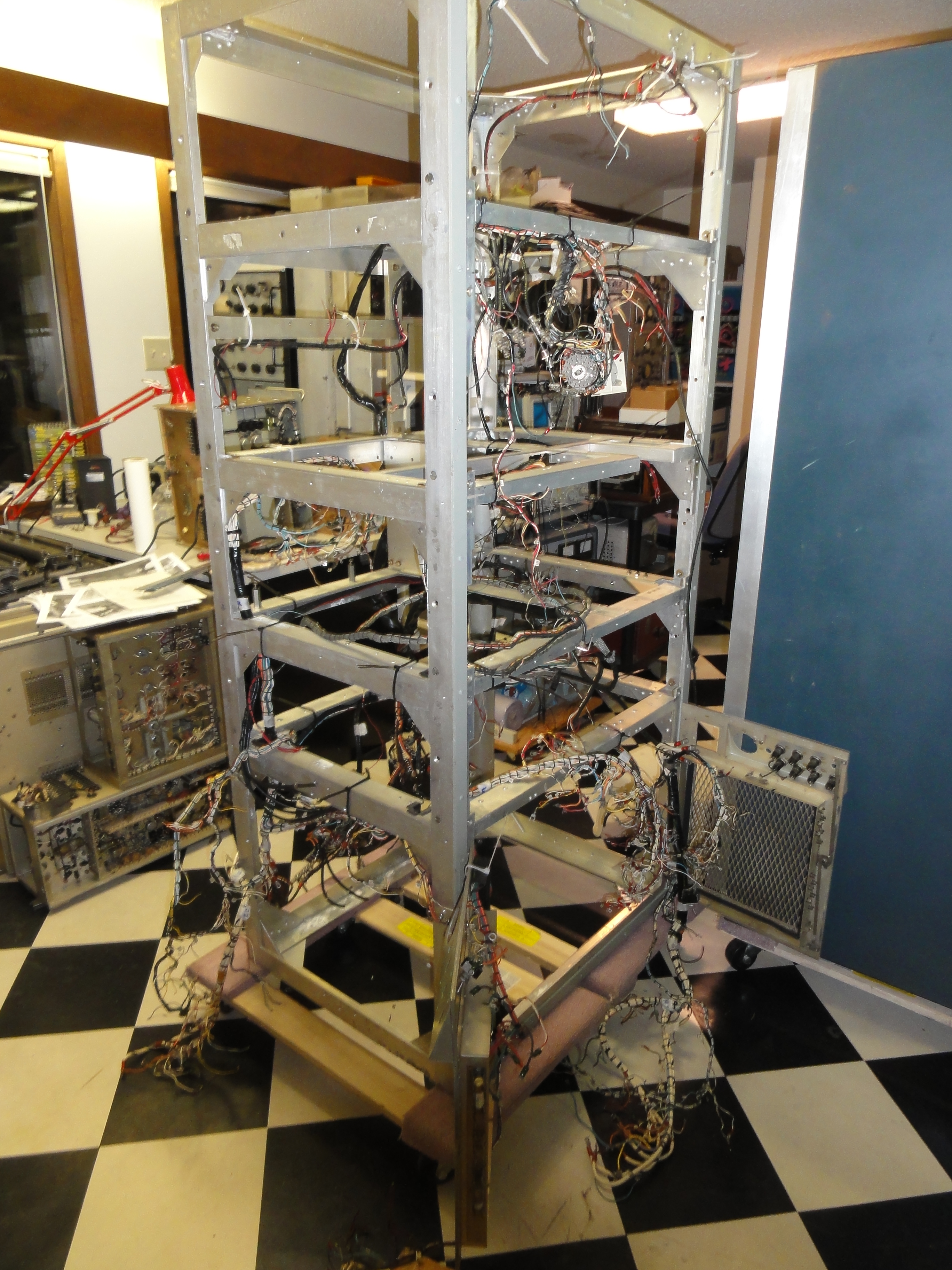
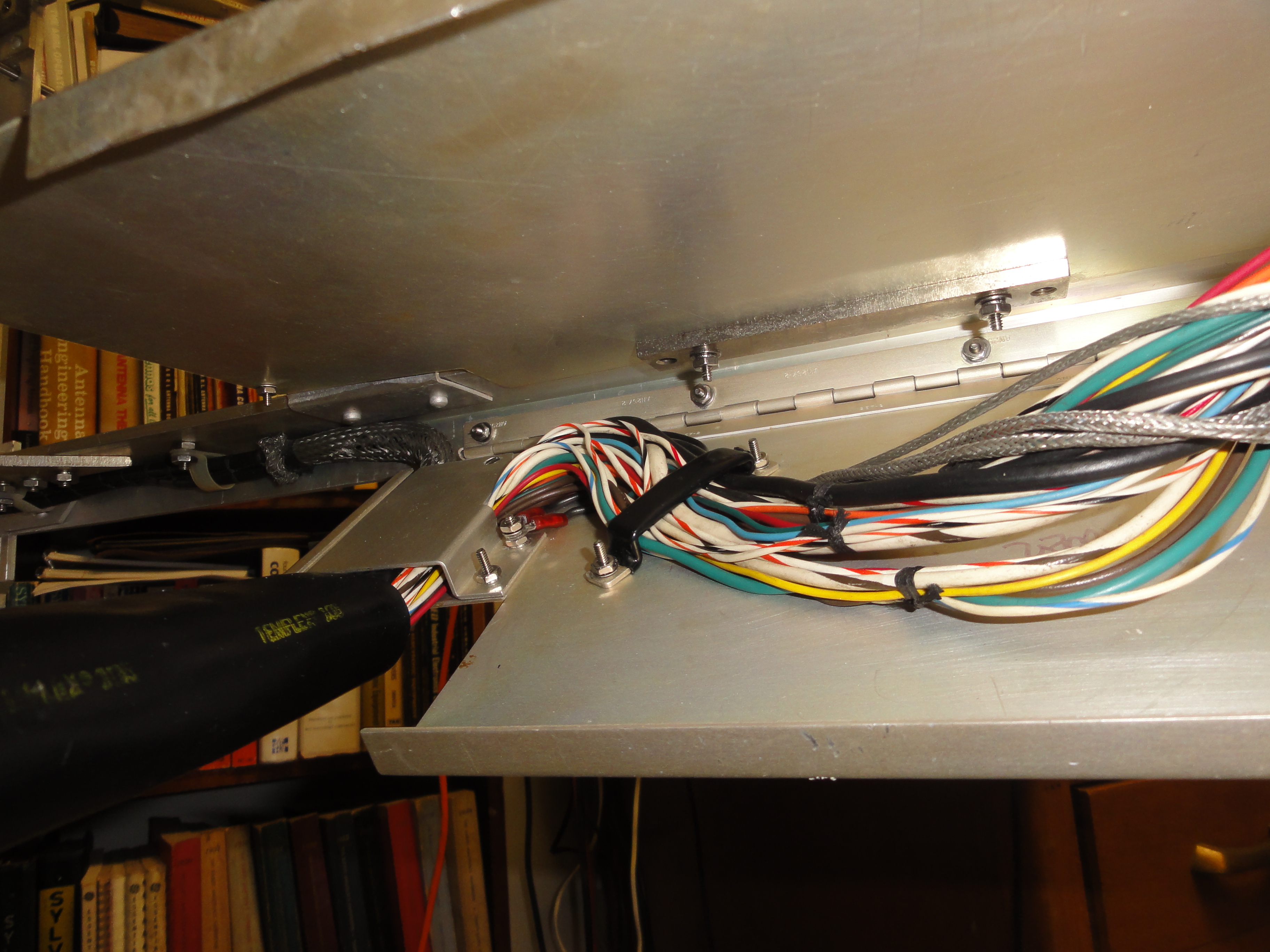
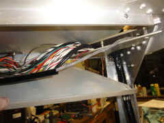
Tie-wraps hold things in approximately the right location
![DSC01525.JPG (3518978 bytes)](frt17/frt17-4/DSC01525_small.JPG) |
![DSC01526.JPG (3510993 bytes)](frt17/frt17-4/DSC01526_small.JPG) |
![DSC01527.JPG (3453443 bytes)](frt17/frt17-4/DSC01527_small.JPG) |
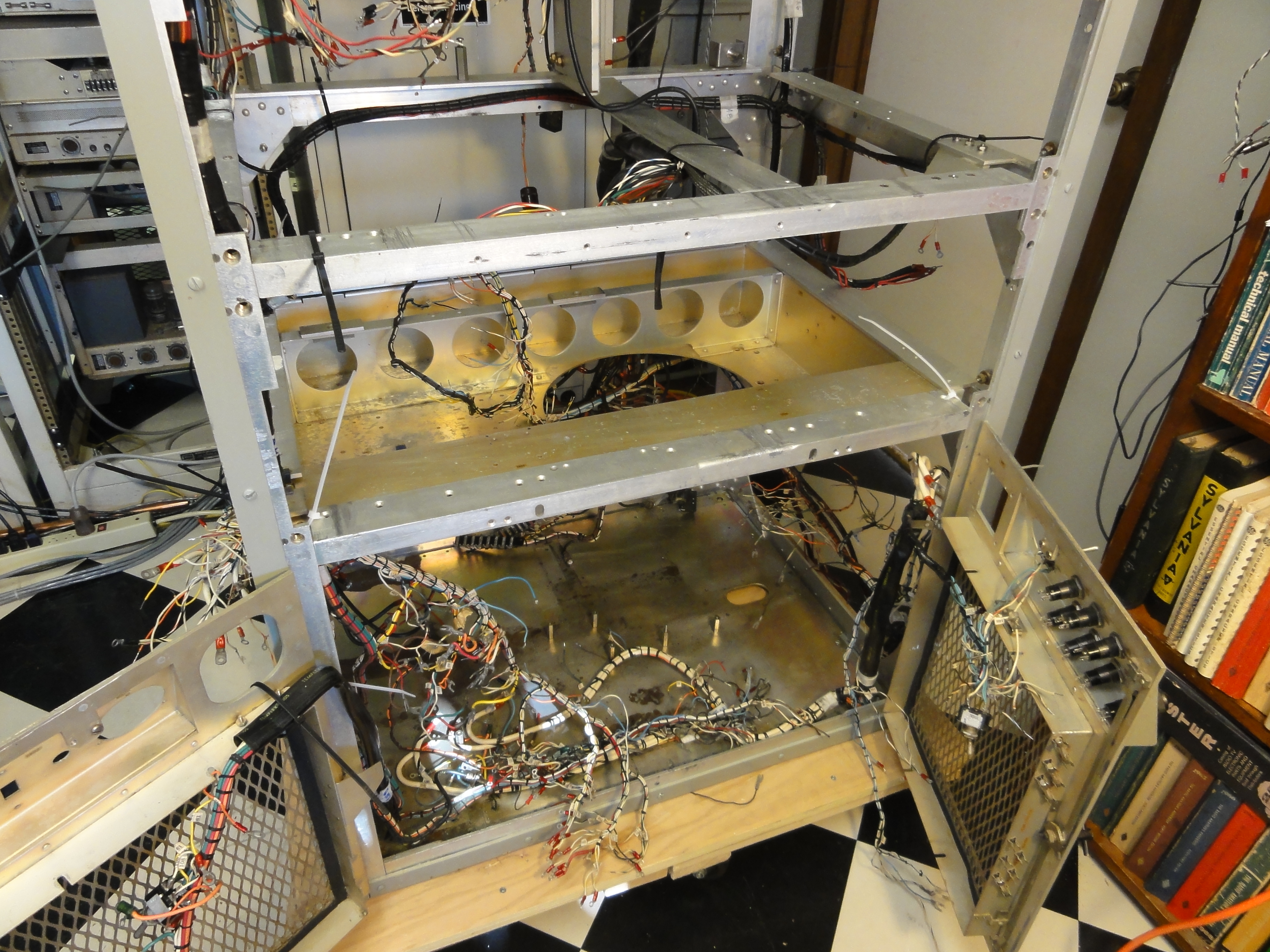
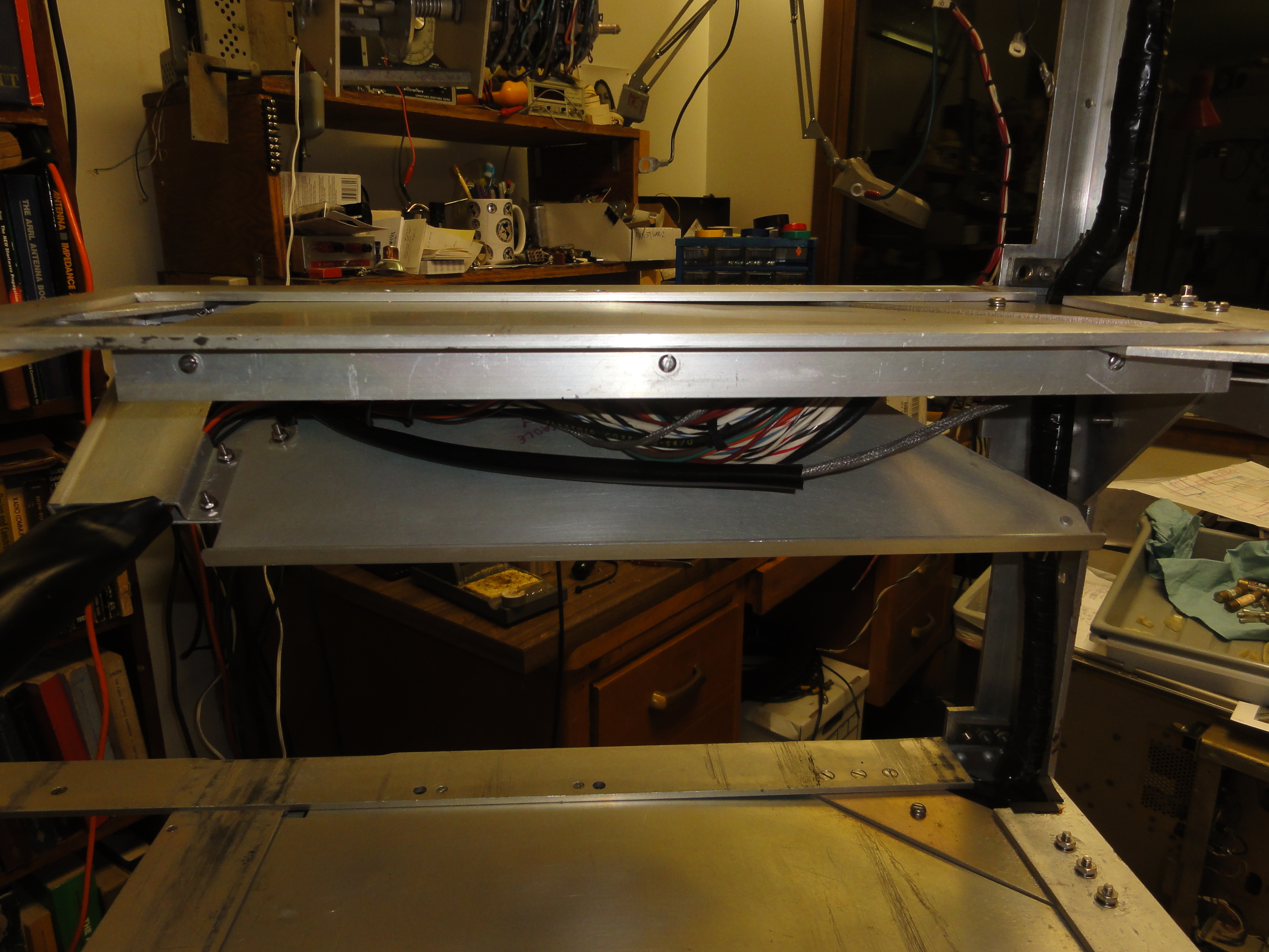
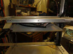
OK, I got this far and then remembered I needed to add the bottom plate!
![DSC01528.JPG (3684484 bytes)](frt17/frt17-4/DSC01528_small.JPG) |
![DSC01529.JPG (3735261 bytes)](frt17/frt17-4/DSC01529_small.JPG) |
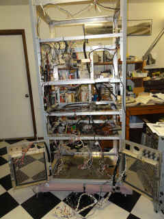
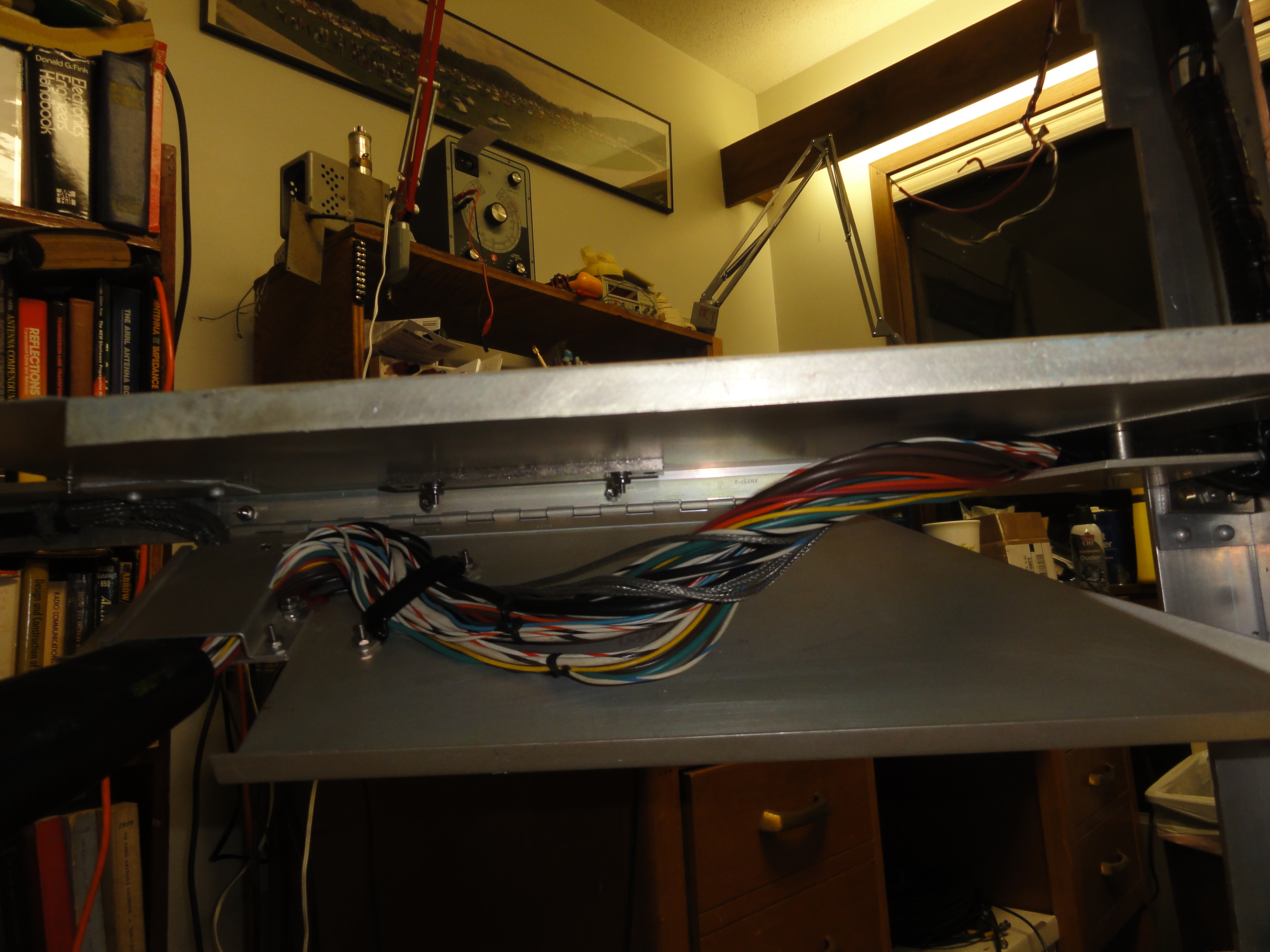
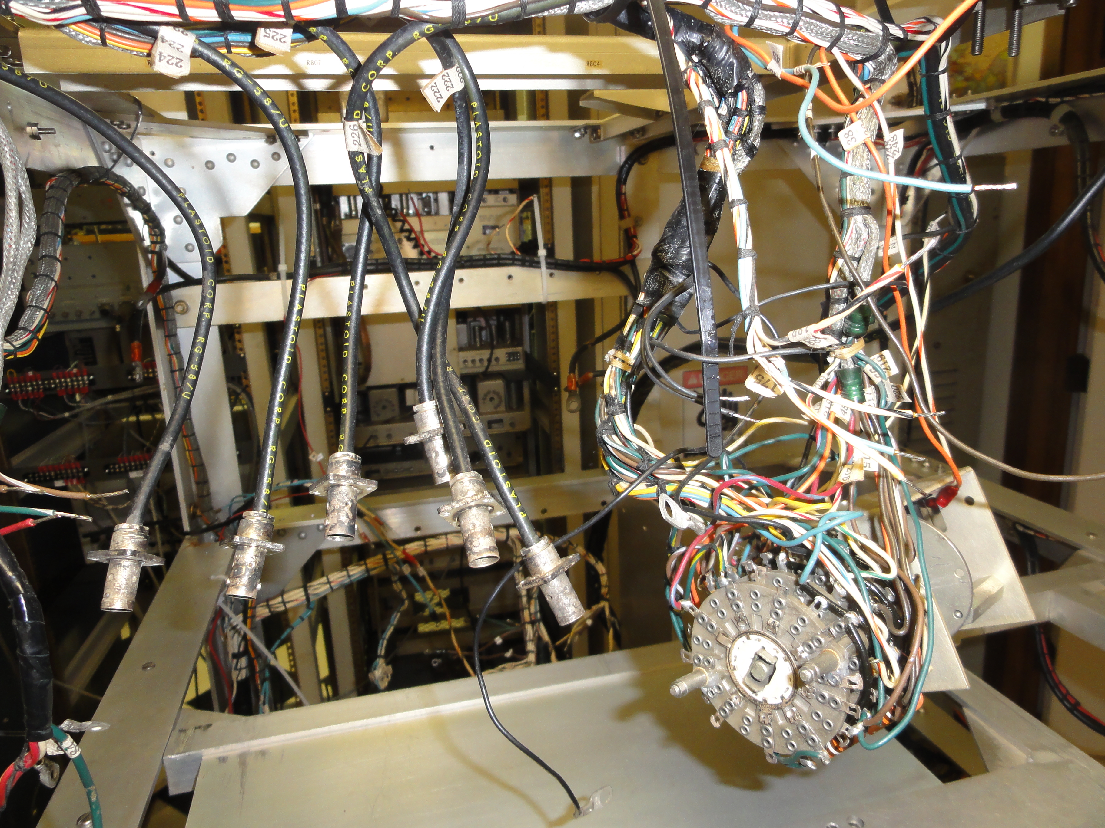
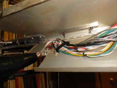
End of day 1 - mostly in the right location - some branches yet to
figure out.
![DSC01530.JPG (3627501 bytes)](frt17/frt17-4/DSC01530_small.JPG) |
1/17/13 - Start re-installing components
|
Observer/Supervisor
![DSC01532.JPG (3235173 bytes)](frt17/frt17-4/DSC01532_small.JPG) |
Strip and tin all the wires
![DSC01533.JPG (3427643 bytes)](frt17/frt17-4/DSC01533_small.JPG) |
Ready to begin
![DSC01534.JPG (3609098 bytes)](frt17/frt17-4/DSC01534_small.JPG) |
Fan tray re-installed
![DSC01535.JPG (3378747 bytes)](frt17/frt17-4/DSC01535_small.JPG) |
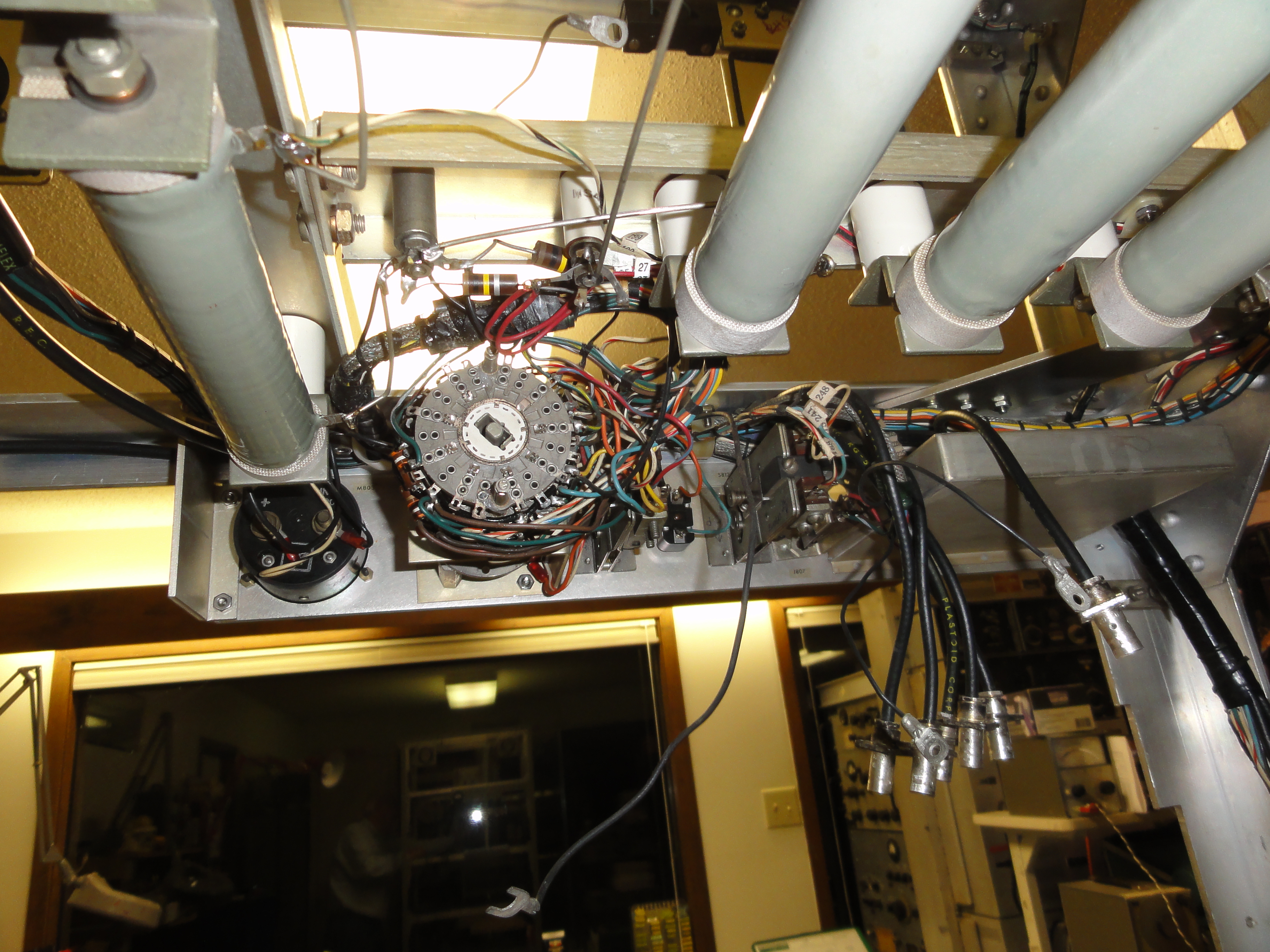
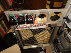
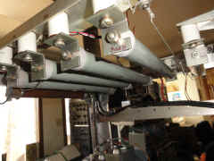
RHS components - these mount hanging down from the fan tray
![DSC01536.JPG (3562304 bytes)](frt17/frt17-4/DSC01536_small.JPG) |
Solder leads, then mount upside down
![DSC01537.JPG (3607747 bytes)](frt17/frt17-4/DSC01537_small.JPG) |
mounted
![DSC01538.JPG (3674690 bytes)](frt17/frt17-4/DSC01538_small.JPG) |
RHS also has terminal strip for connections to AN/FRT-18 amplifier
section
![DSC01539.JPG (3416690 bytes)](frt17/frt17-4/DSC01539_small.JPG) |
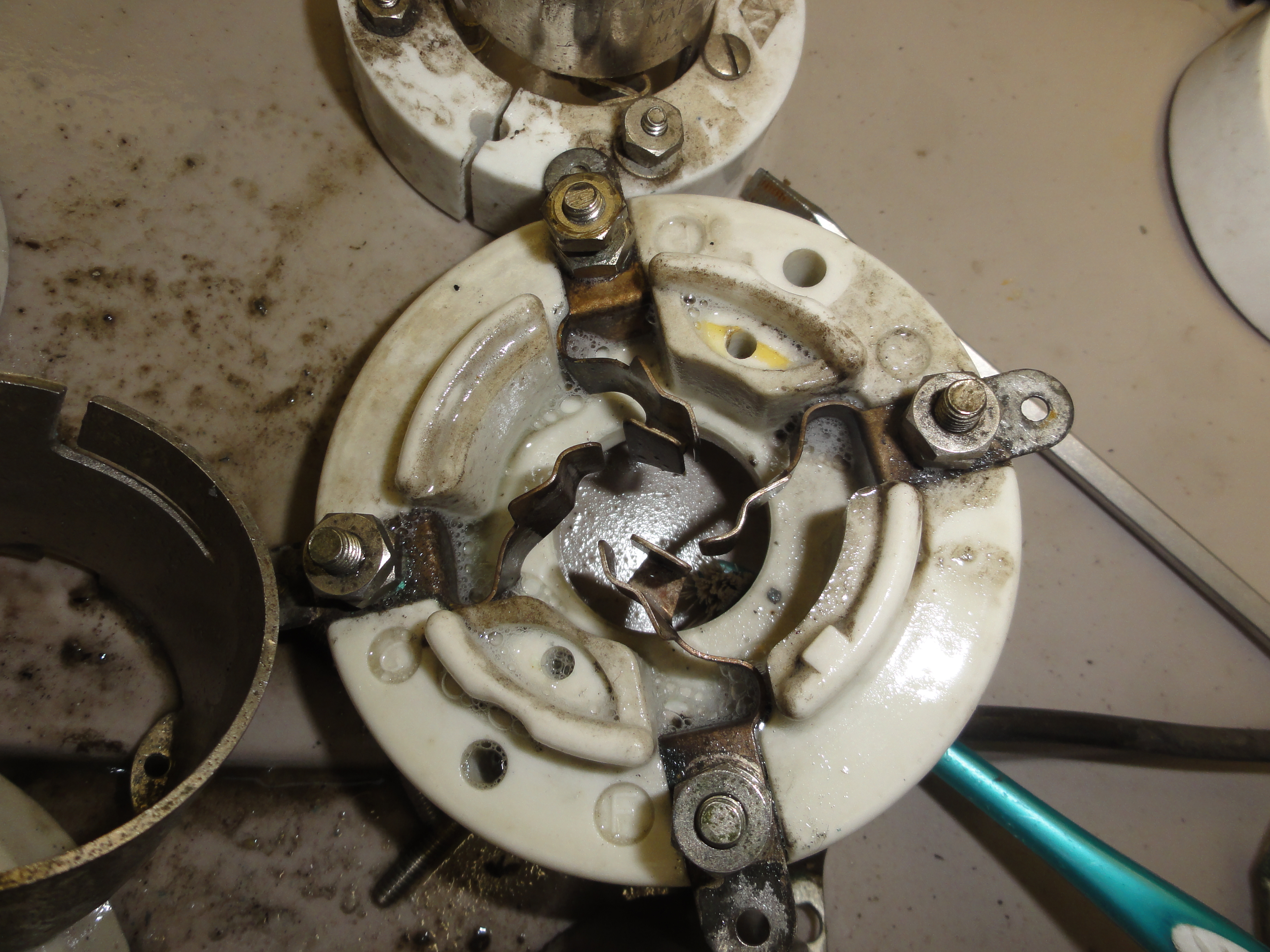
HV rectifier socket cleaning
![DSC01540.JPG (3427001 bytes)](frt17/frt17-4/DSC01540_small.JPG) |
RH door wired
![DSC01541.JPG (3587137 bytes)](frt17/frt17-4/DSC01541_small.JPG) |
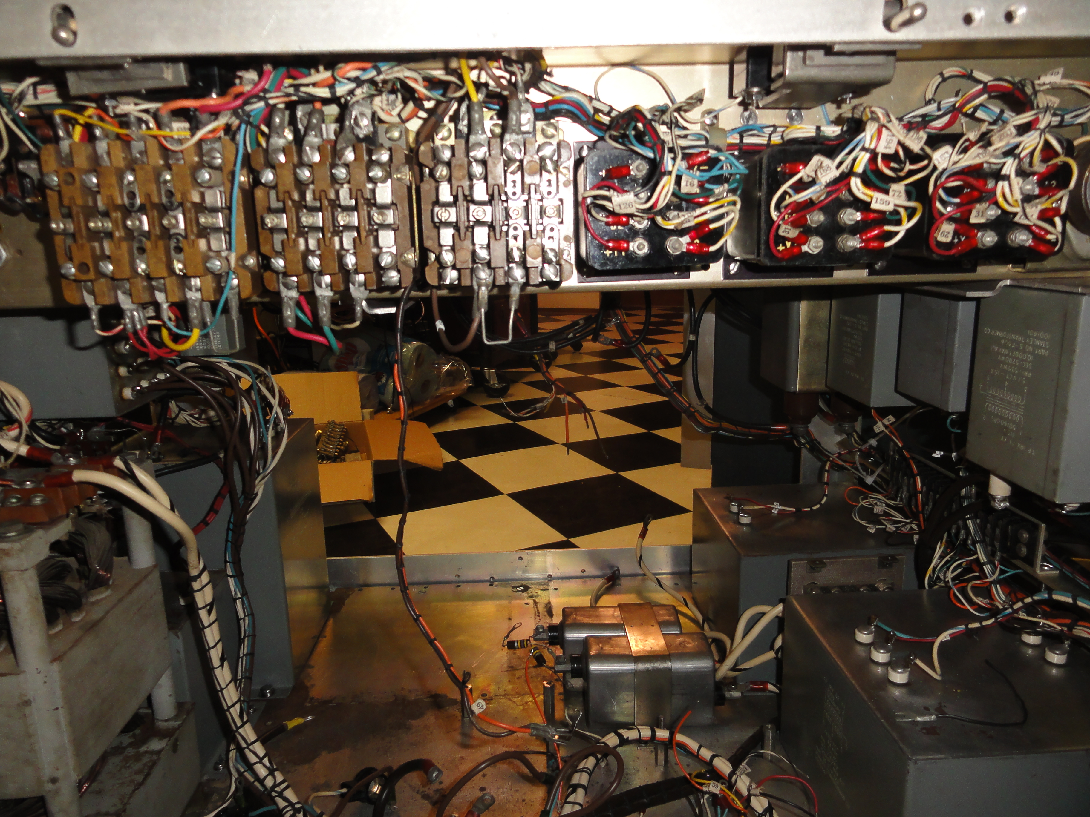
Bottom deck components
![DSC01542.JPG (3419452 bytes)](frt17/frt17-4/DSC01542_small.JPG) |
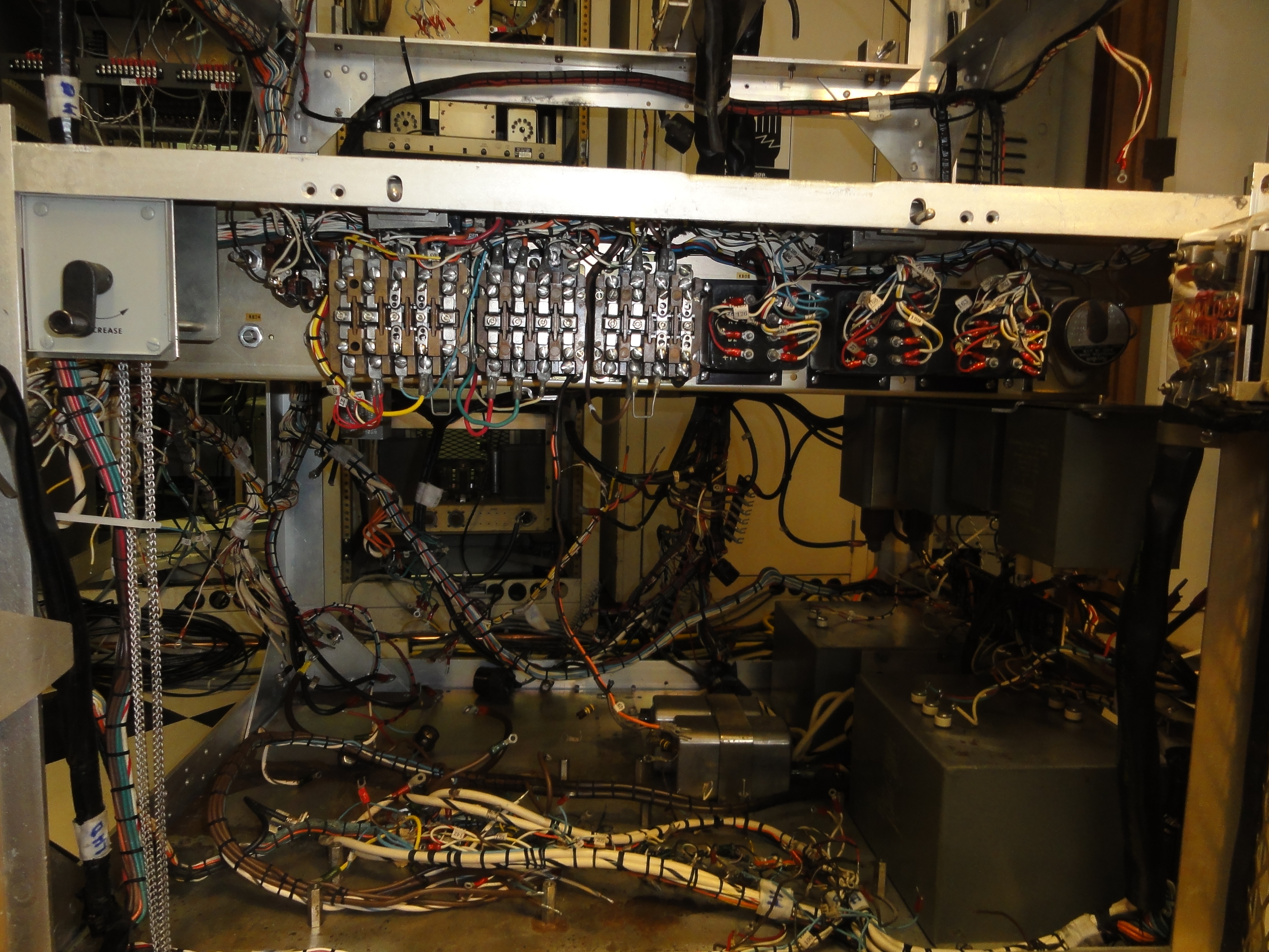
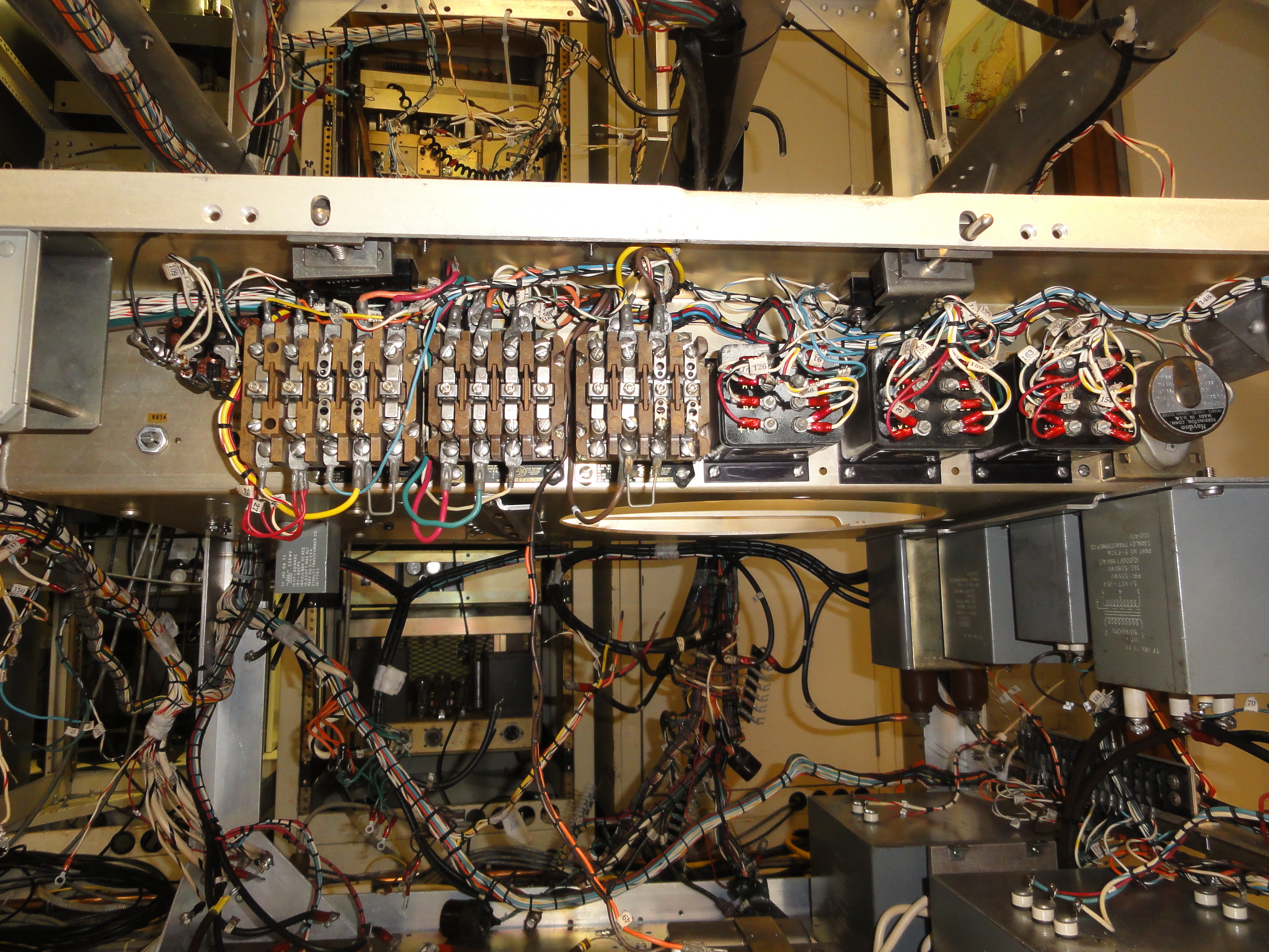
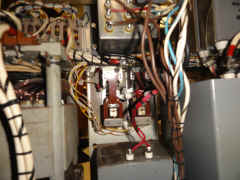
re-installing control relays
![DSC01543.JPG (3624812 bytes)](frt17/frt17-4/DSC01543_small.JPG) |
![DSC01544.JPG (3470852 bytes)](frt17/frt17-4/DSC01544_small.JPG) |
![DSC01545.JPG (3621442 bytes)](frt17/frt17-4/DSC01545_small.JPG) |
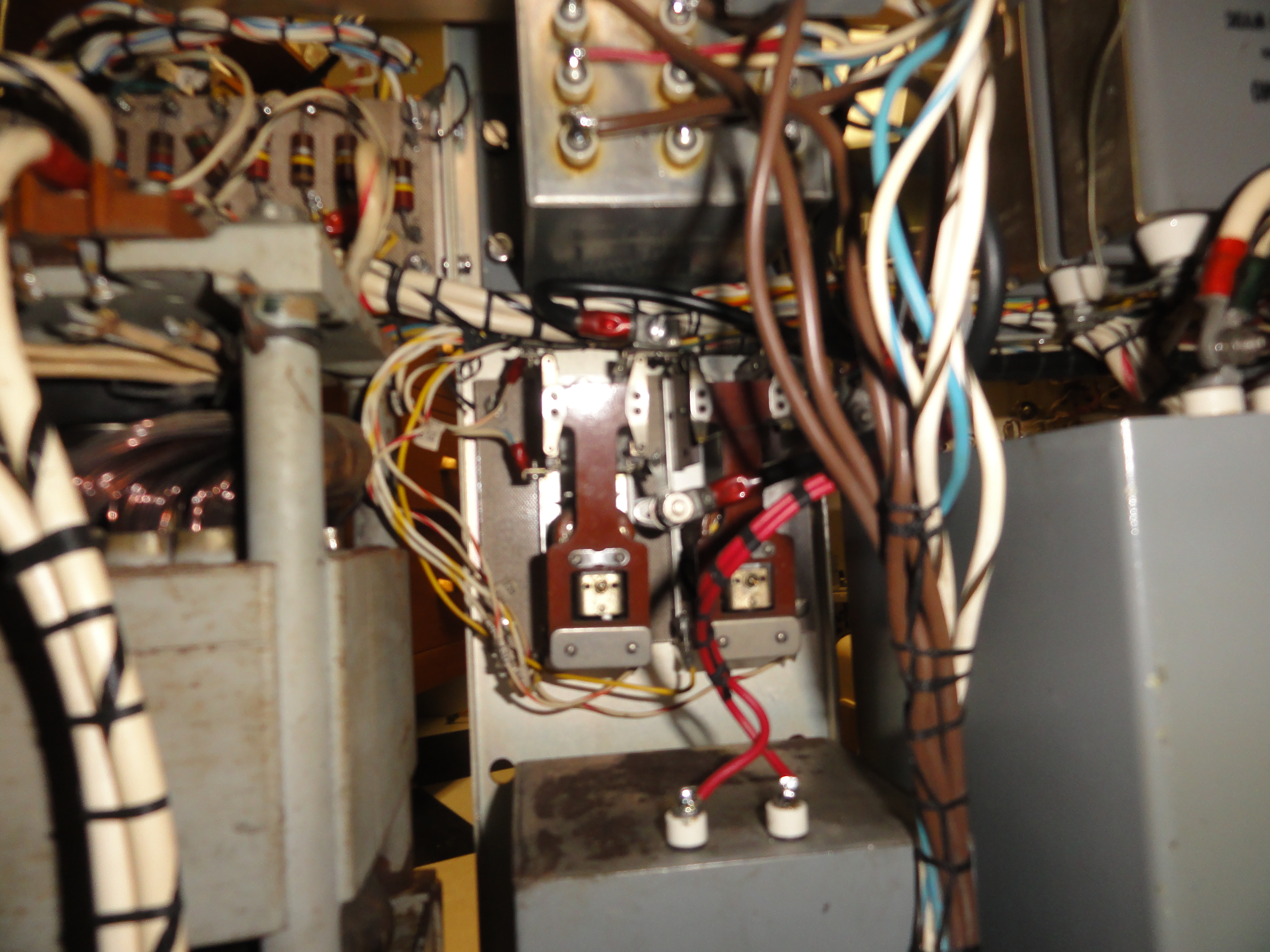
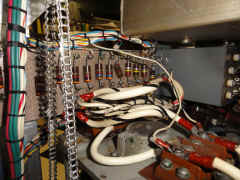
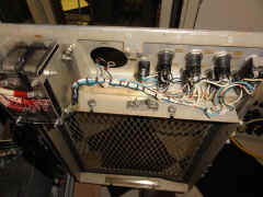
LHS - terminal board, HV relays, and MV filament xfmr
![DSC01549.JPG (3730896 bytes)](frt17/frt17-4/DSC01549_small.JPG) |
It took many tries to get all this stuff squeezed into place. install,
remove, re-route, re-install, repeat as necessary.
![DSC01550.JPG (3425037 bytes)](frt17/frt17-4/DSC01550_small.JPG) |
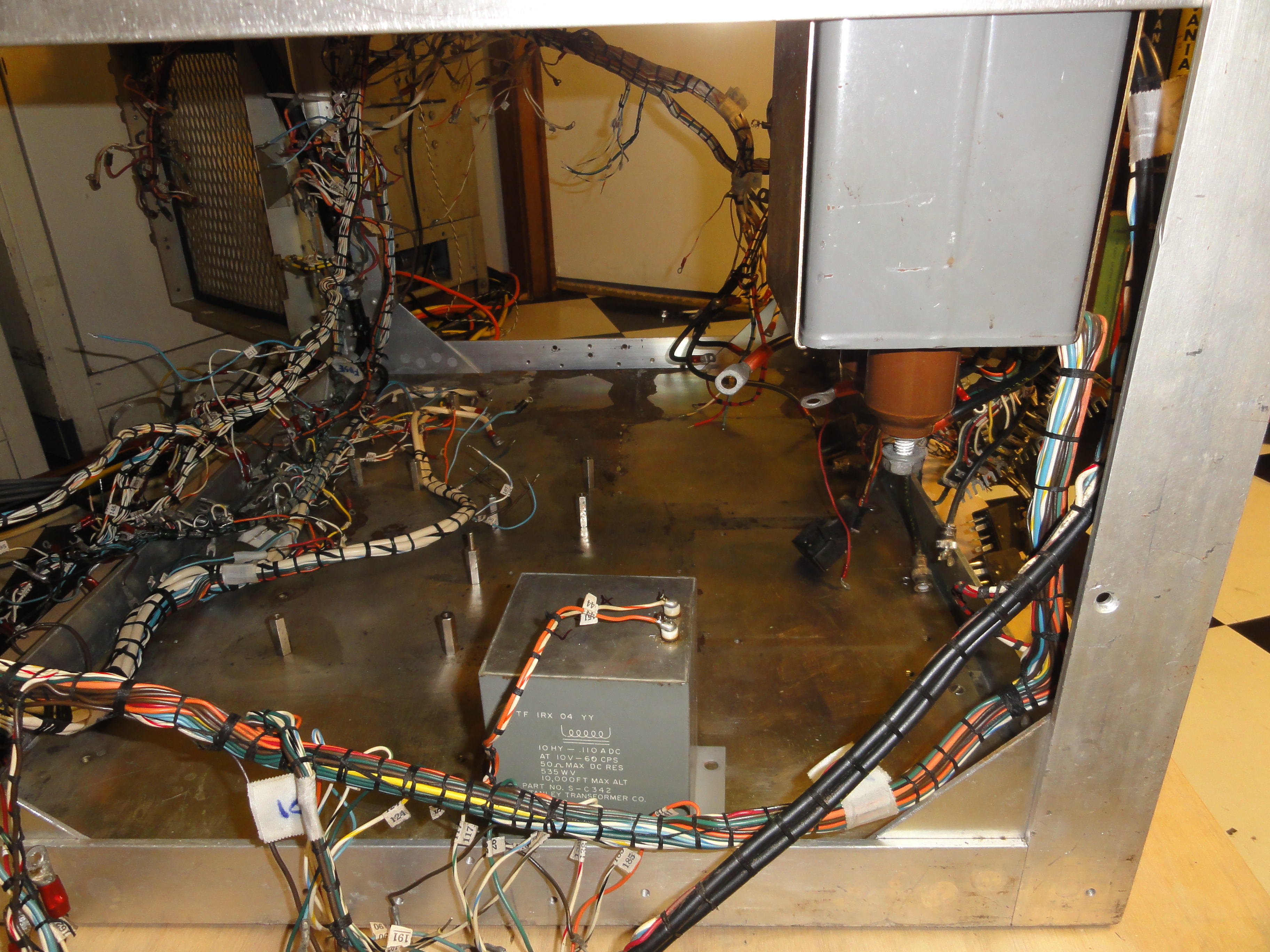
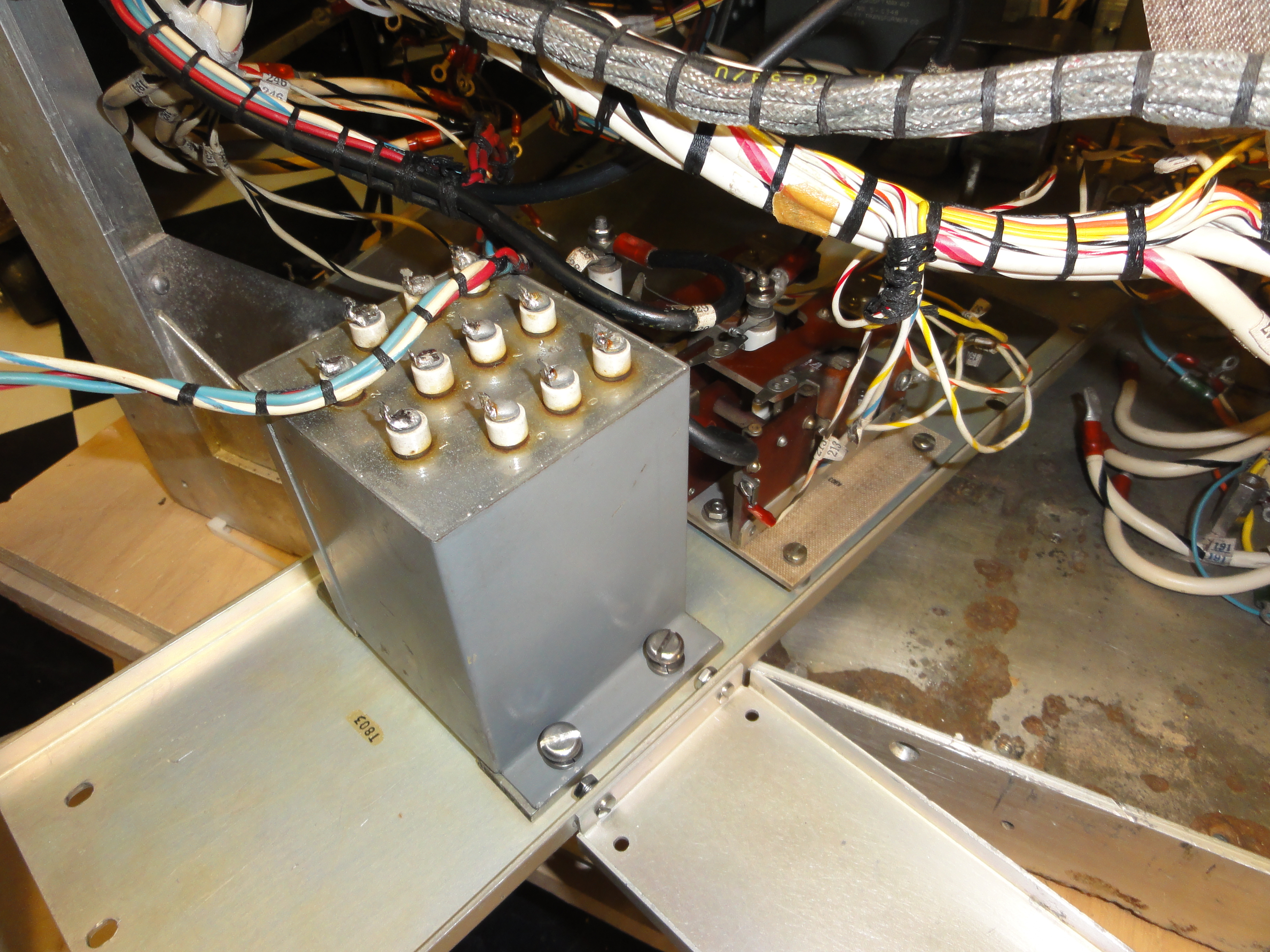
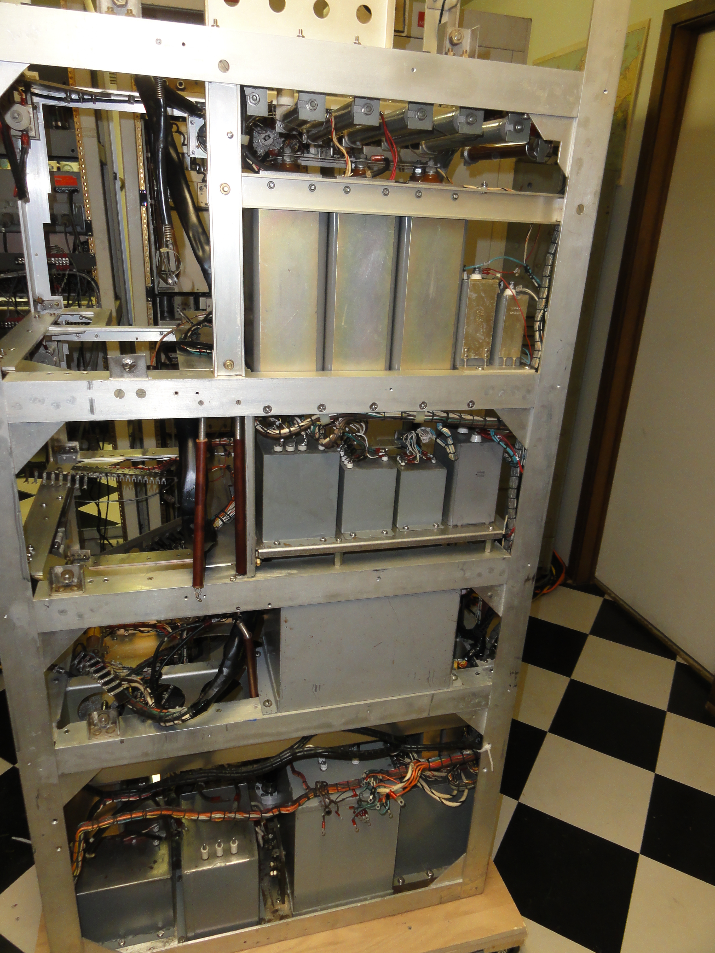
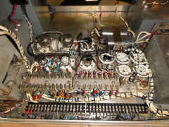
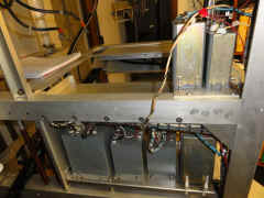
1/31/13 Landmark of sorts, everything in the lower compartment but the
rectifiers
(and HV plate xfmr
and choke at the rear which will go in last)
|
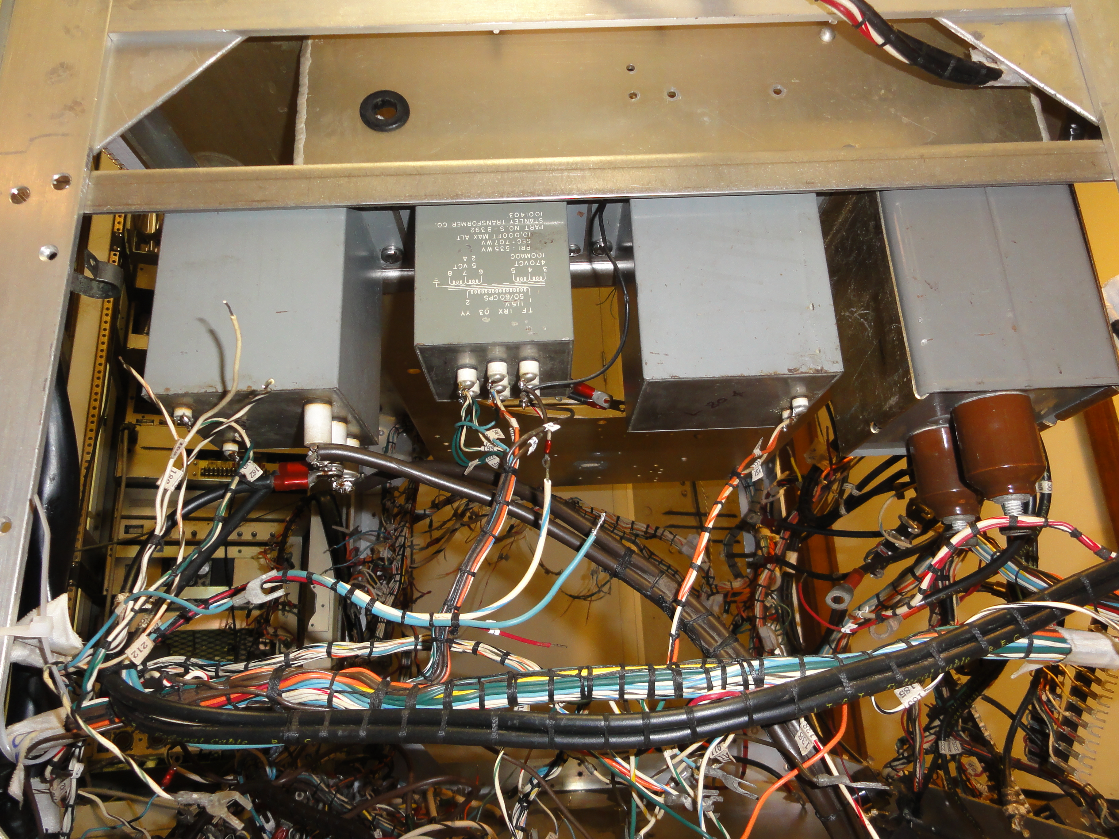
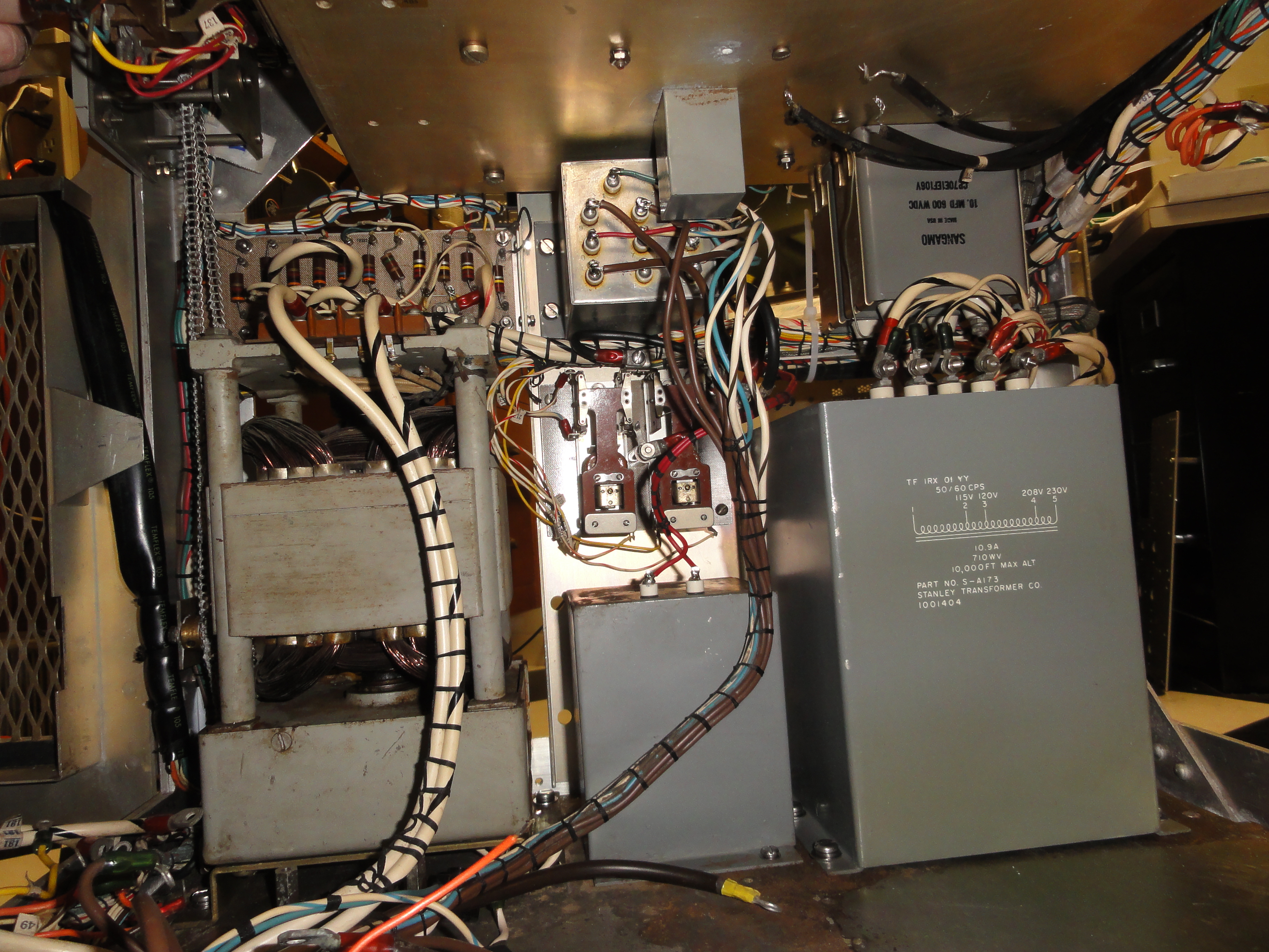
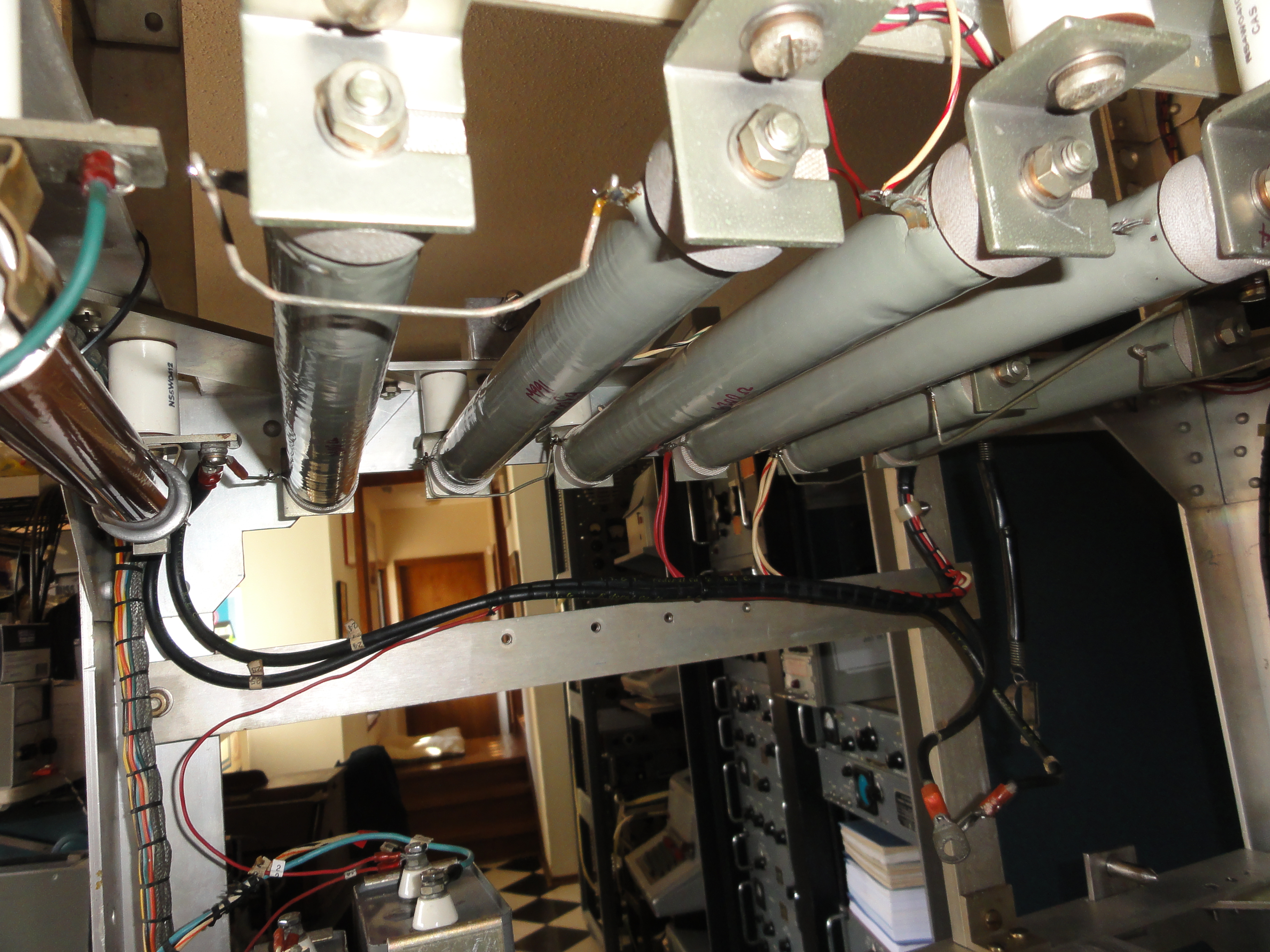
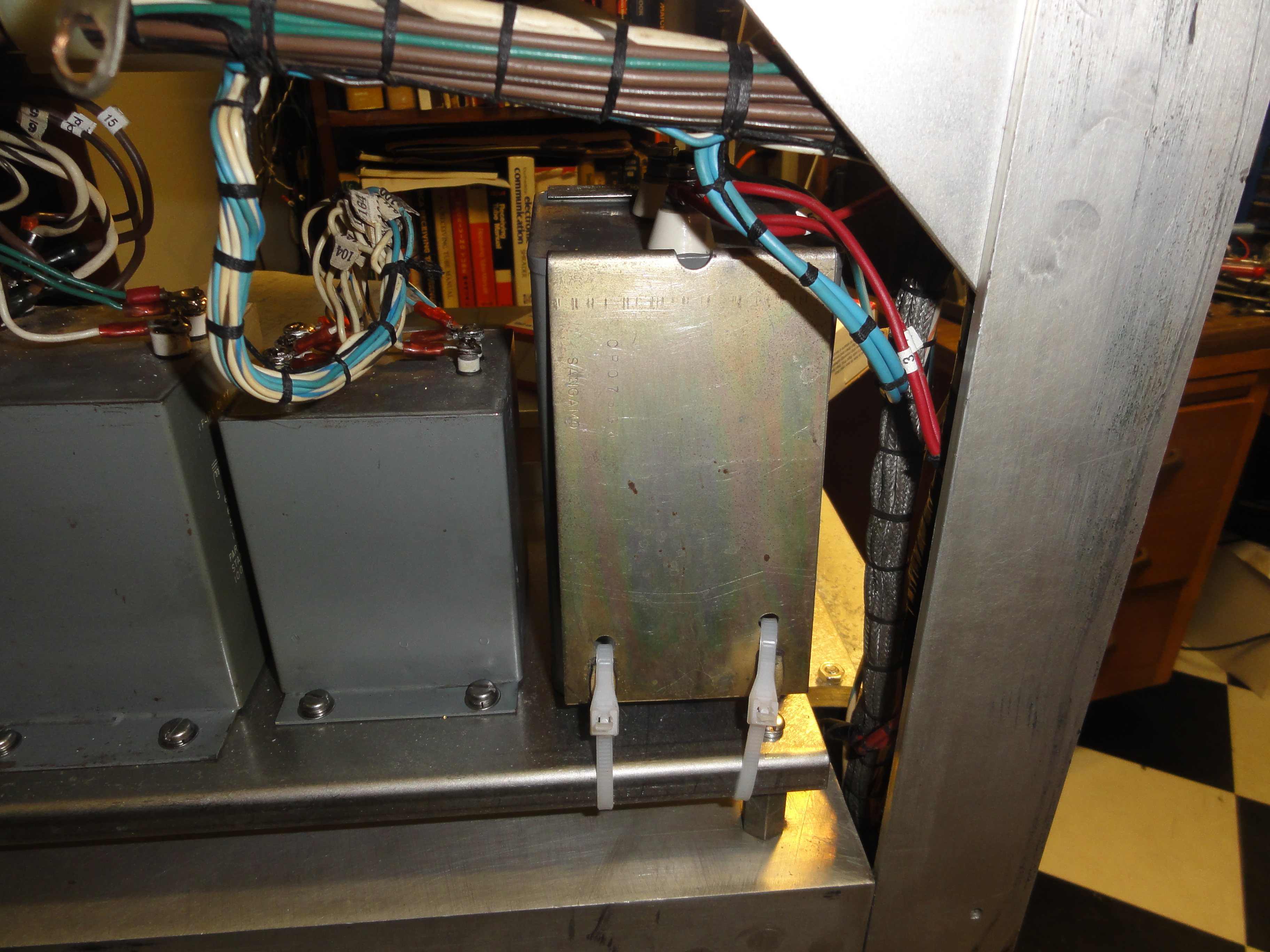
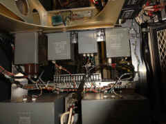
RHS power supply section
![DSC01551.JPG (3411140 bytes)](frt17/frt17-4/DSC01551_small.JPG) |
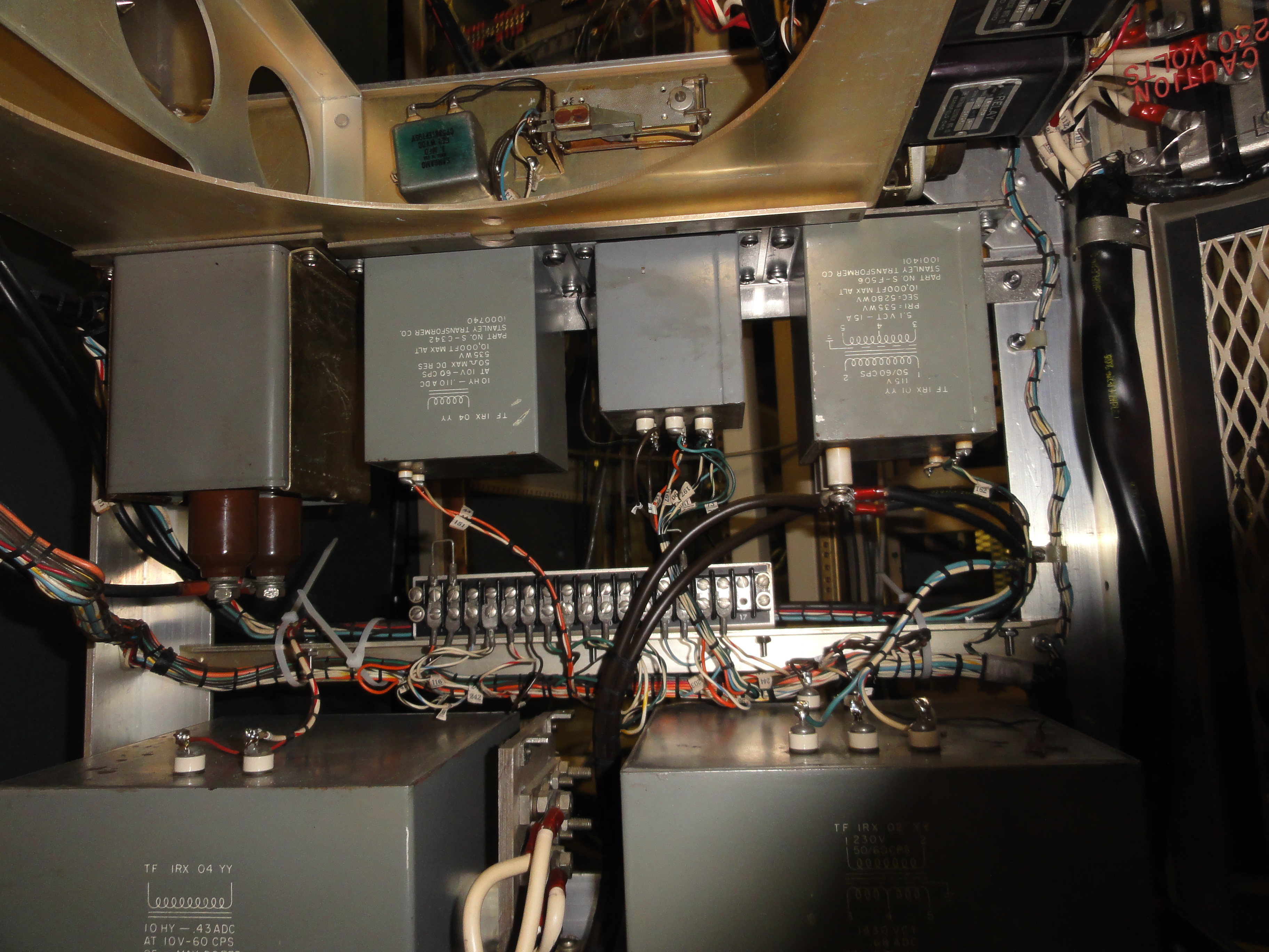
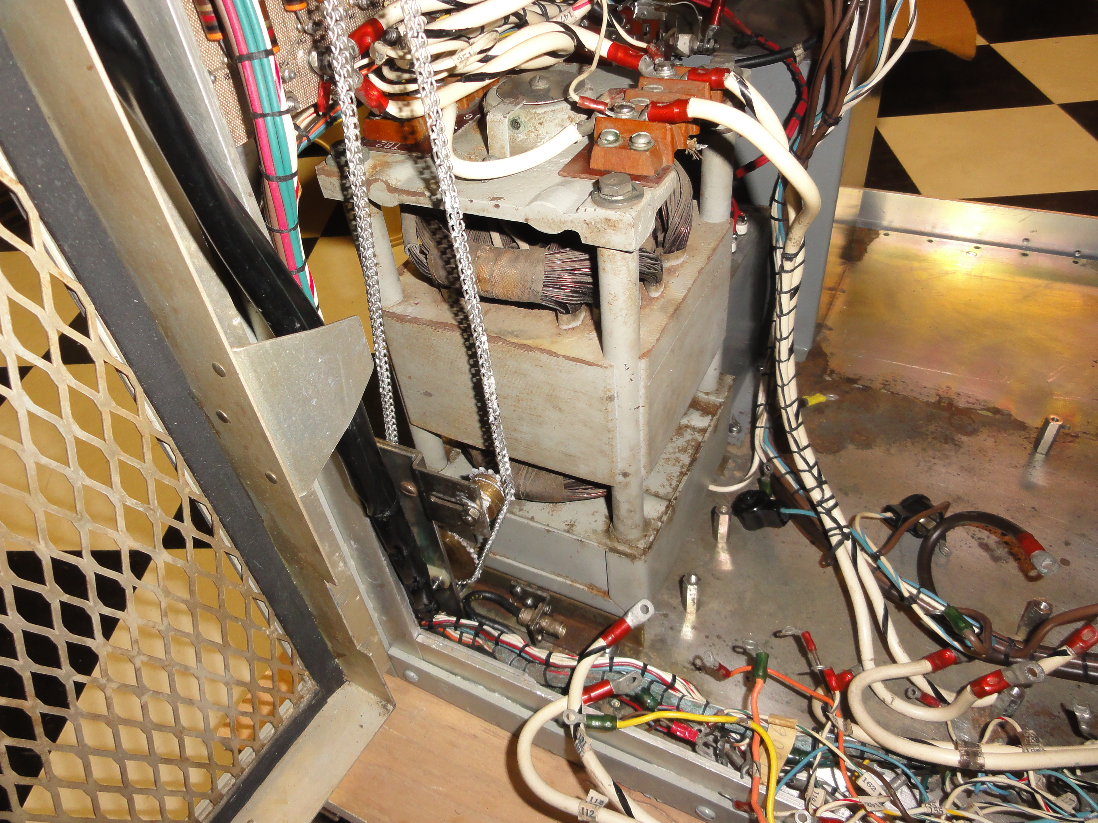
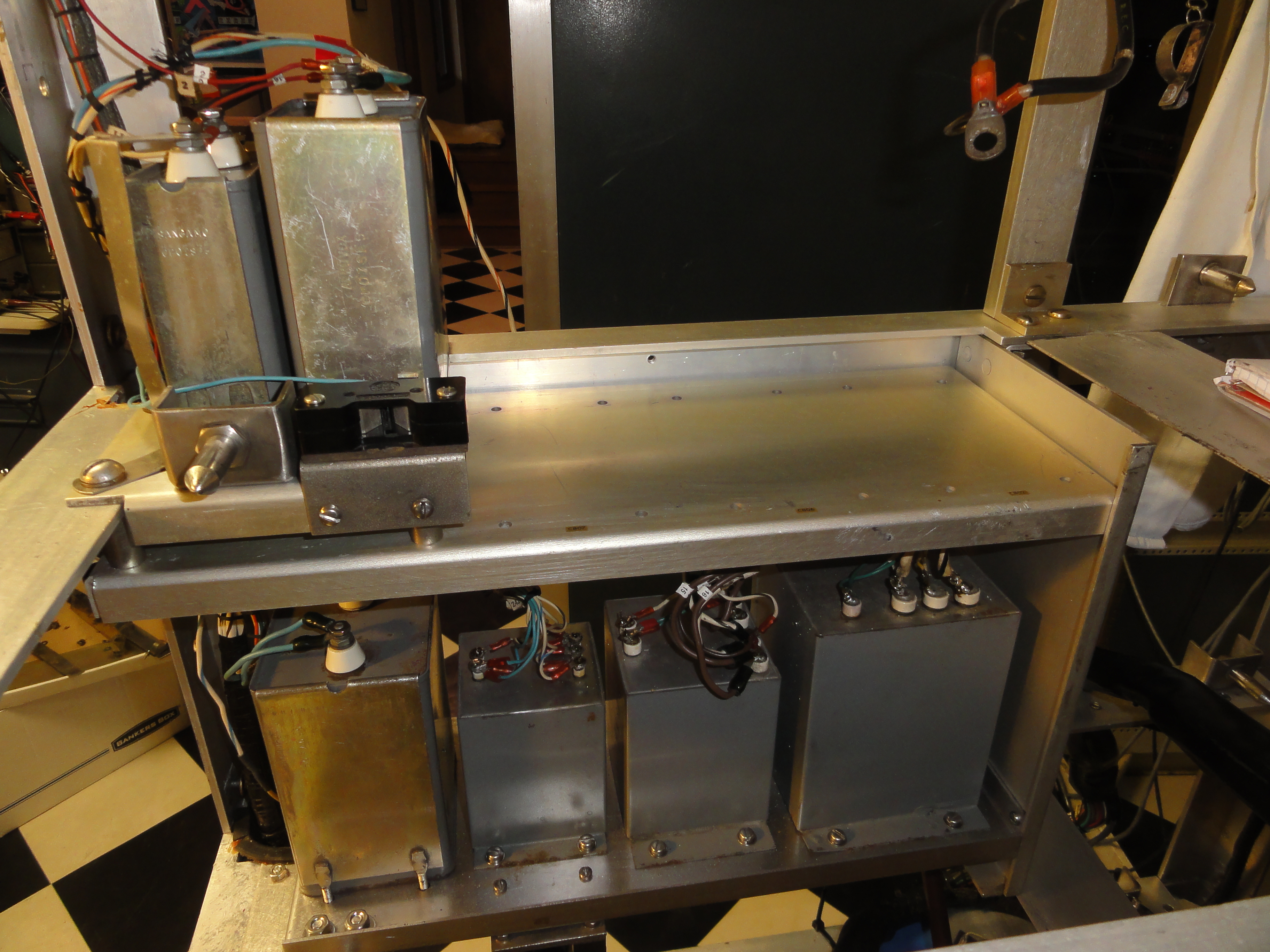
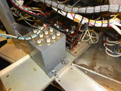
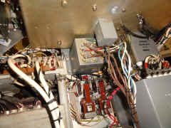
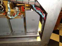
LHS power supply section with voltage regulator, LV choke, LV caps,and
autoxfmr installed
![DSC01552.JPG (3509297 bytes)](frt17/frt17-4/DSC01552_small.JPG) |
![DSC01554.JPG (3604817 bytes)](frt17/frt17-4/DSC01554_small.JPG) |
![DSC01555.JPG (3346298 bytes)](frt17/frt17-4/DSC01555_small.JPG) |
![DSC01556.JPG (3460706 bytes)](frt17/frt17-4/DSC01556_small.JPG) |
![DSC01557.JPG (3679425 bytes)](frt17/frt17-4/DSC01557_small.JPG) |
power supply section
![DSC01553.JPG (3505005 bytes)](frt17/frt17-4/DSC01553_small.JPG) |
-- |
LH door
![DSC01559.JPG (3466186 bytes)](frt17/frt17-4/DSC01559_small.JPG) |
RH door
![DSC01558.JPG (3529879 bytes)](frt17/frt17-4/DSC01558_small.JPG) |
-- |
-- |
Slow but steady progress finishing the power supply compartment
|
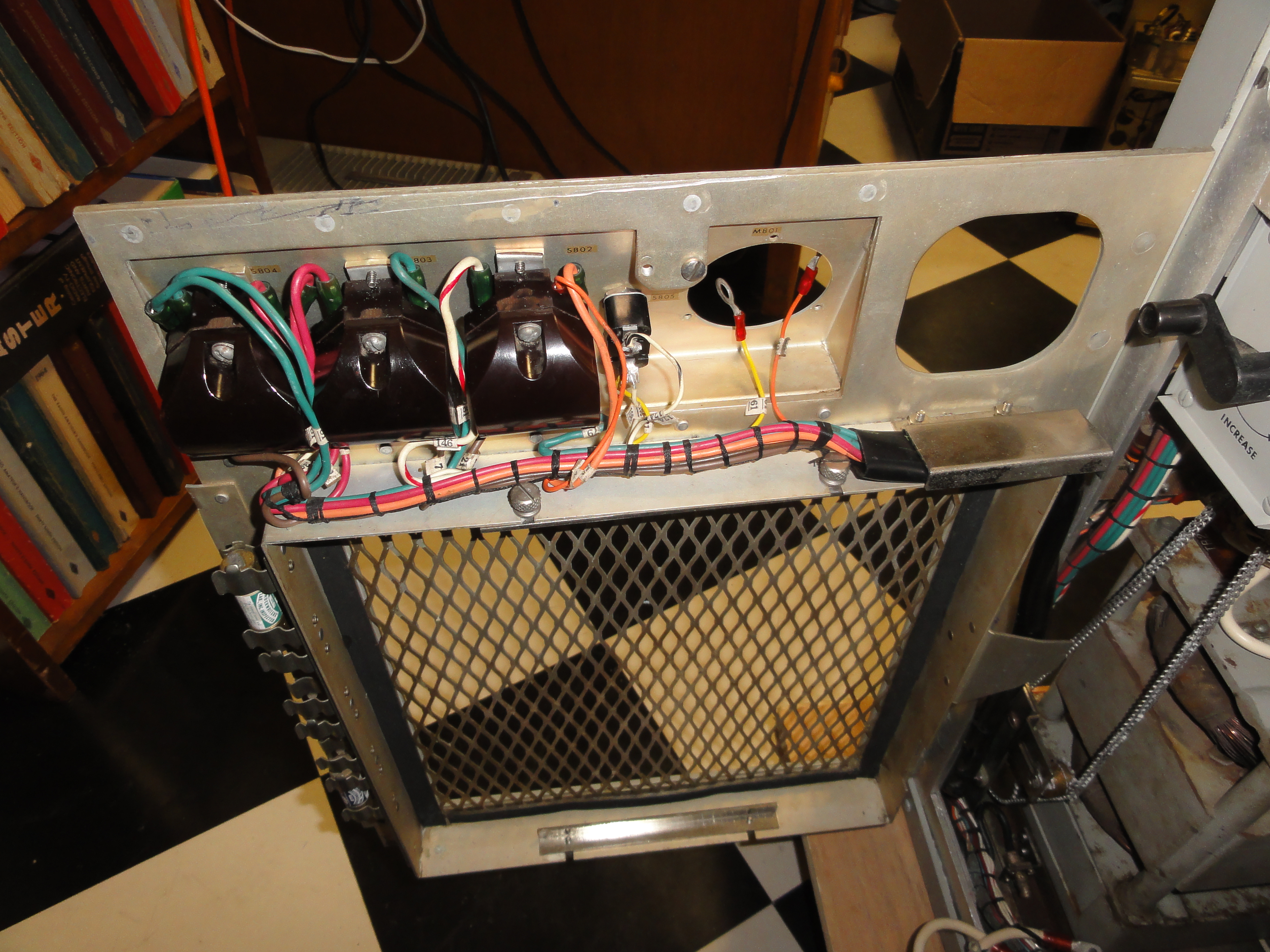
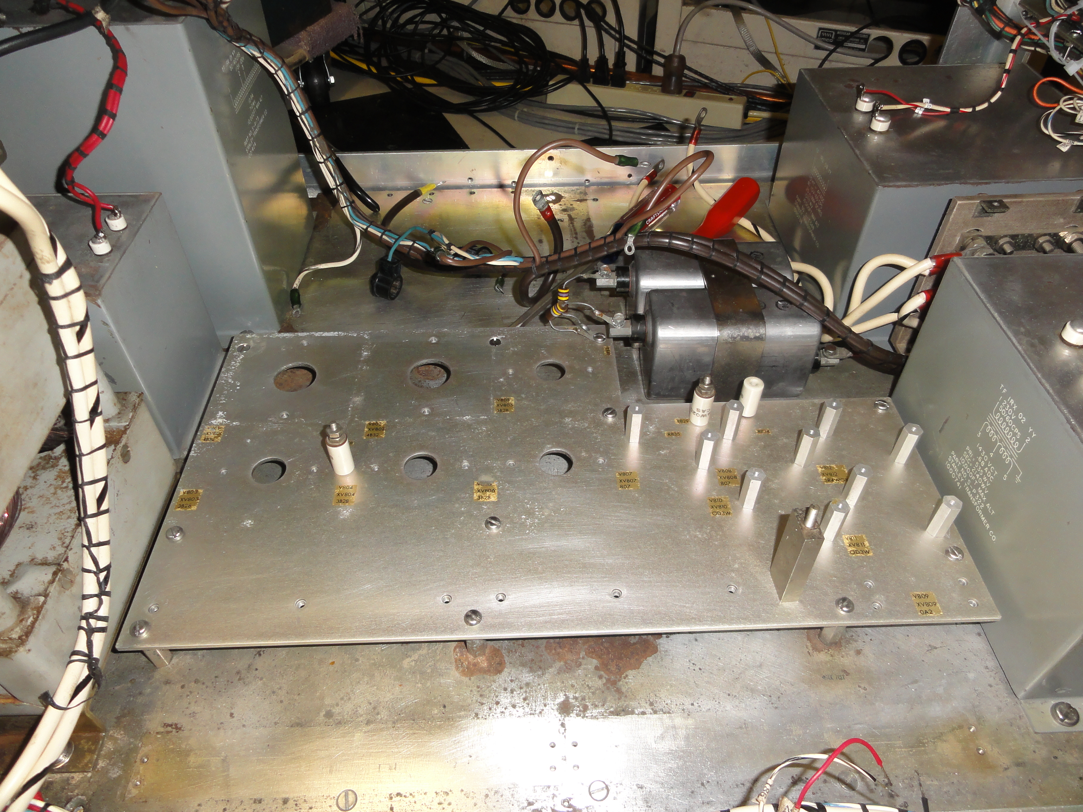
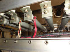
Rectifier mounting plate
![DSC01560.JPG (4370388 bytes)](frt17/frt17-4/DSC01560_small.JPG) |
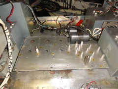
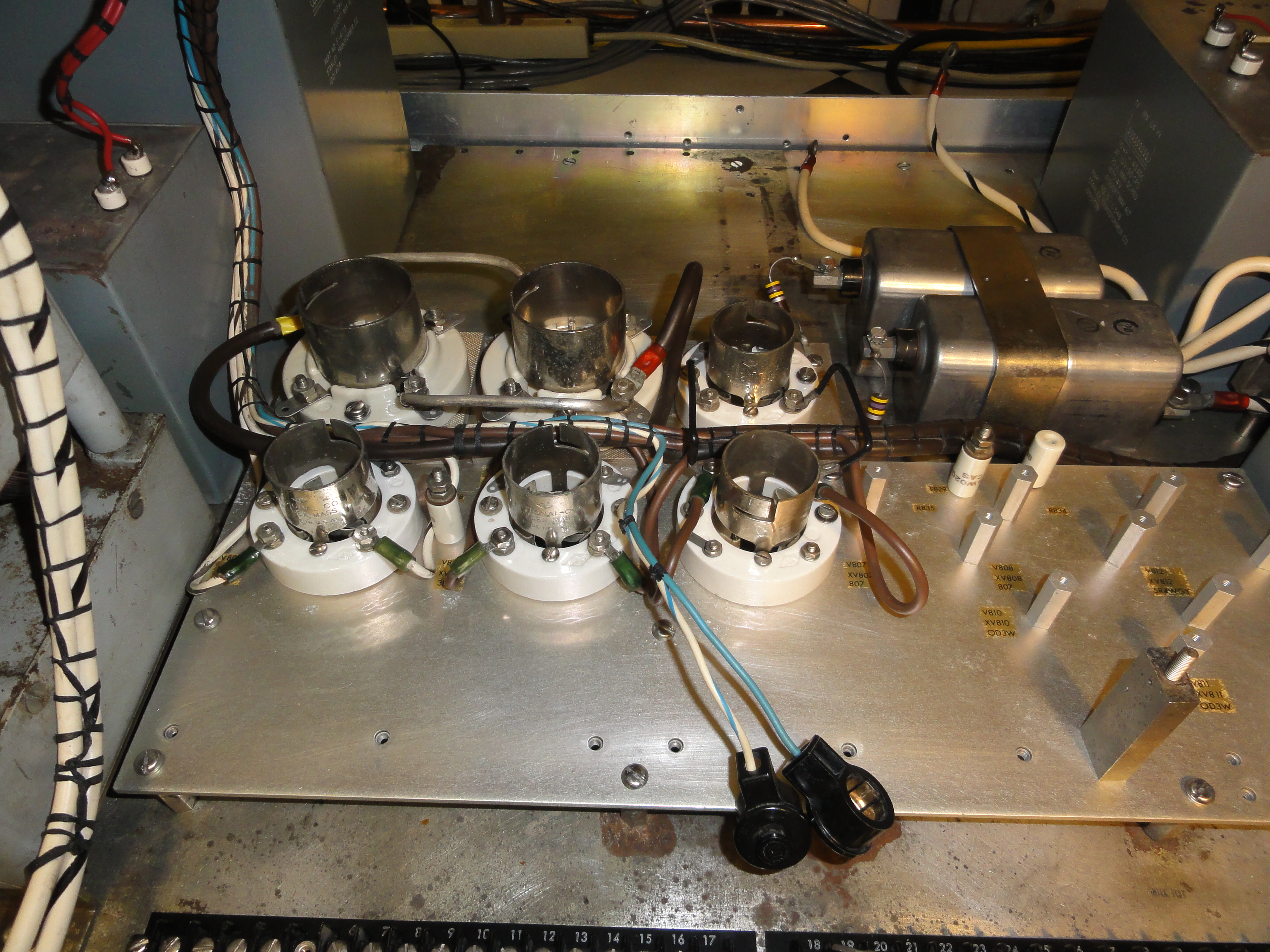
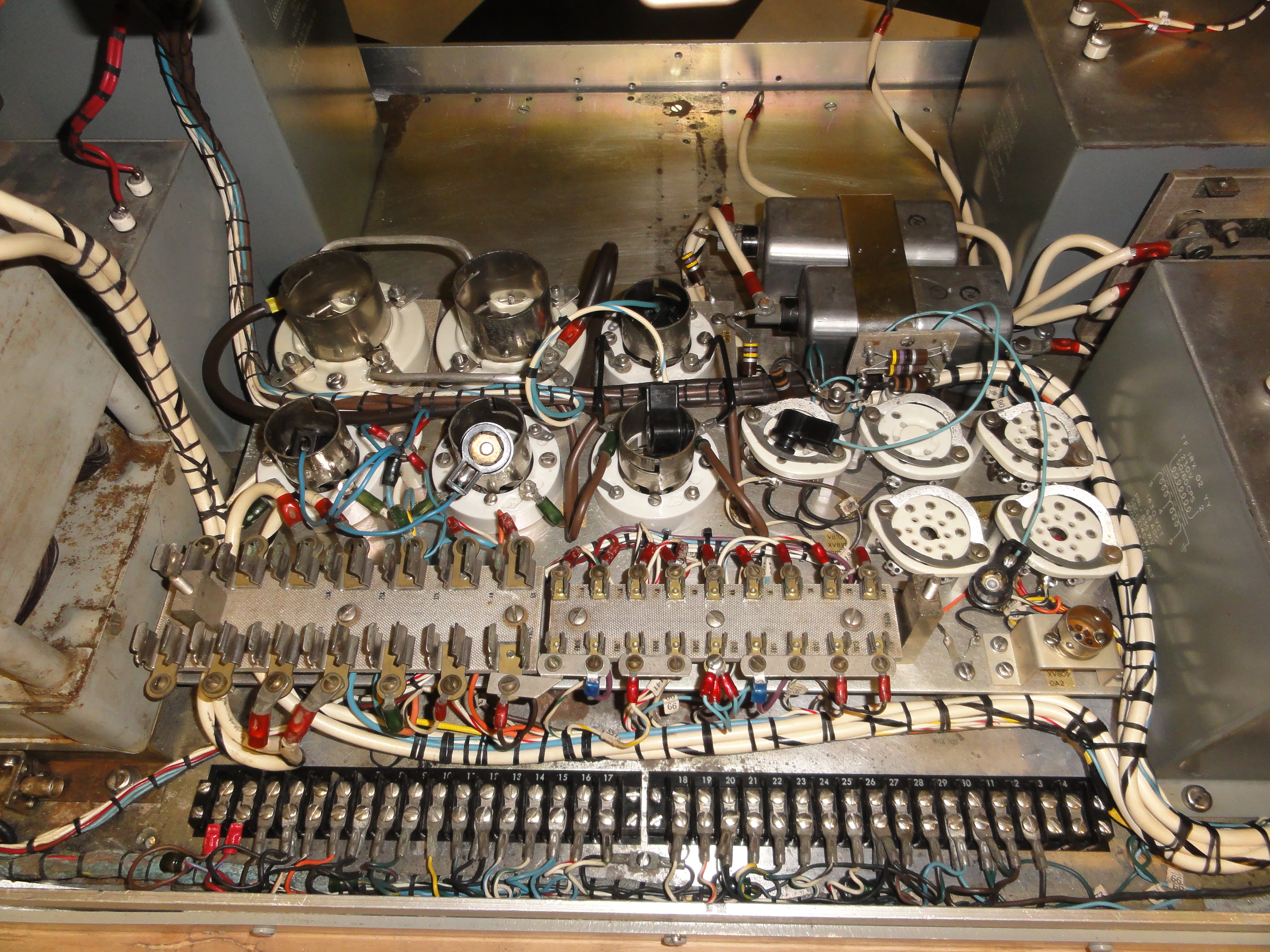
install and wire newly cleaned sockets
![DSC01561.JPG (4320789 bytes)](frt17/frt17-4/DSC01561_small.JPG) |
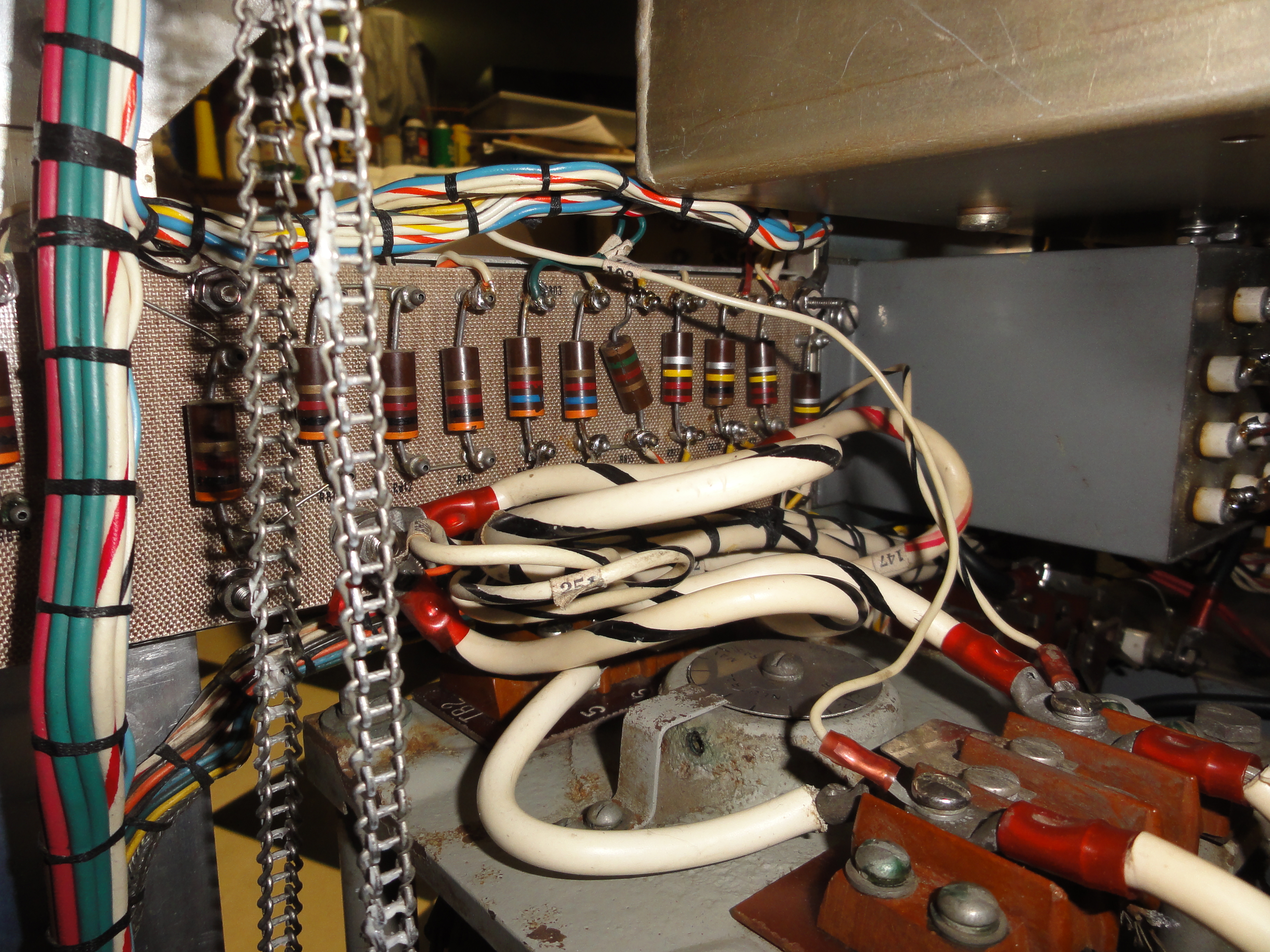
Ditto the terminal strips and regulator section
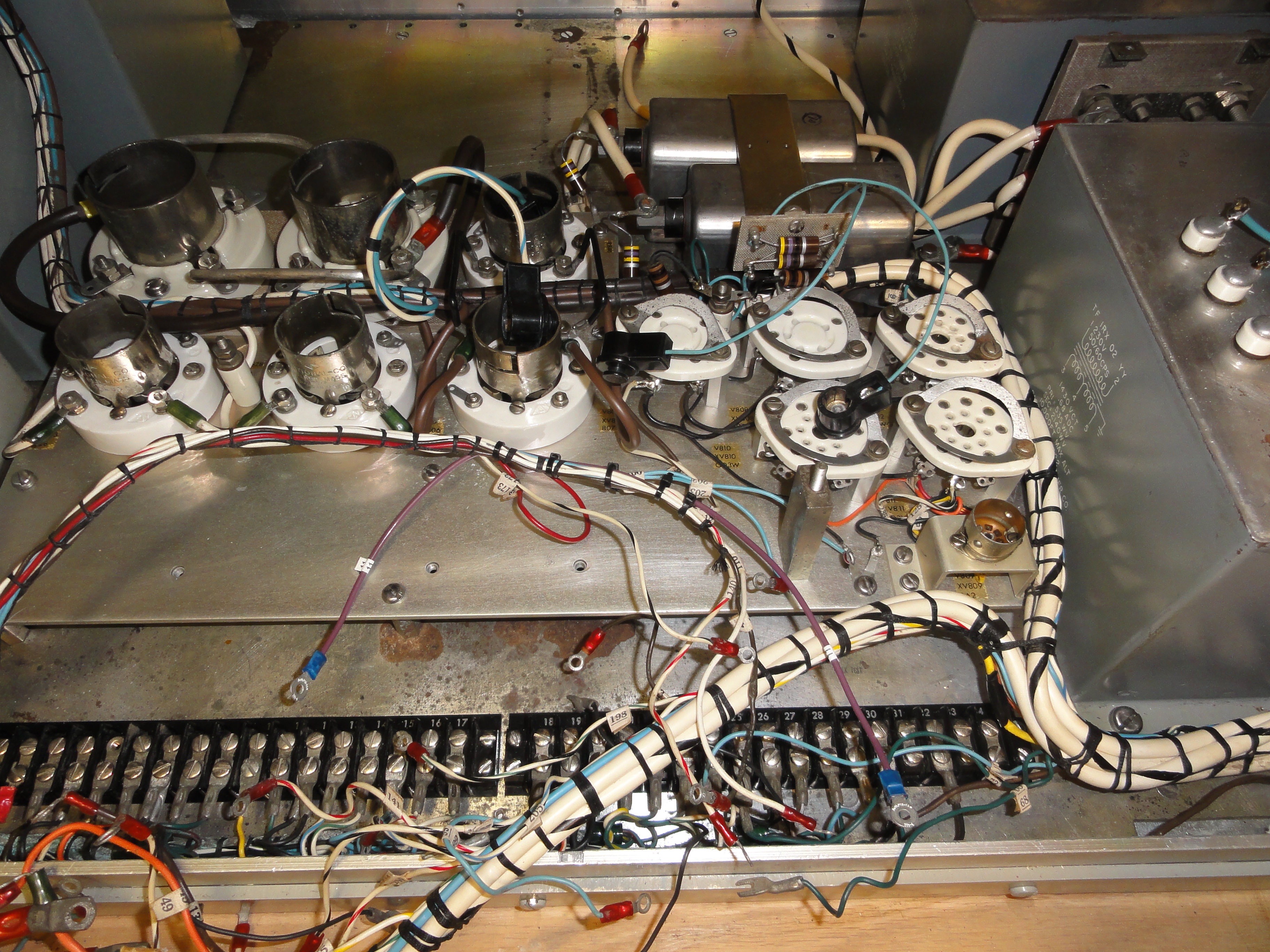
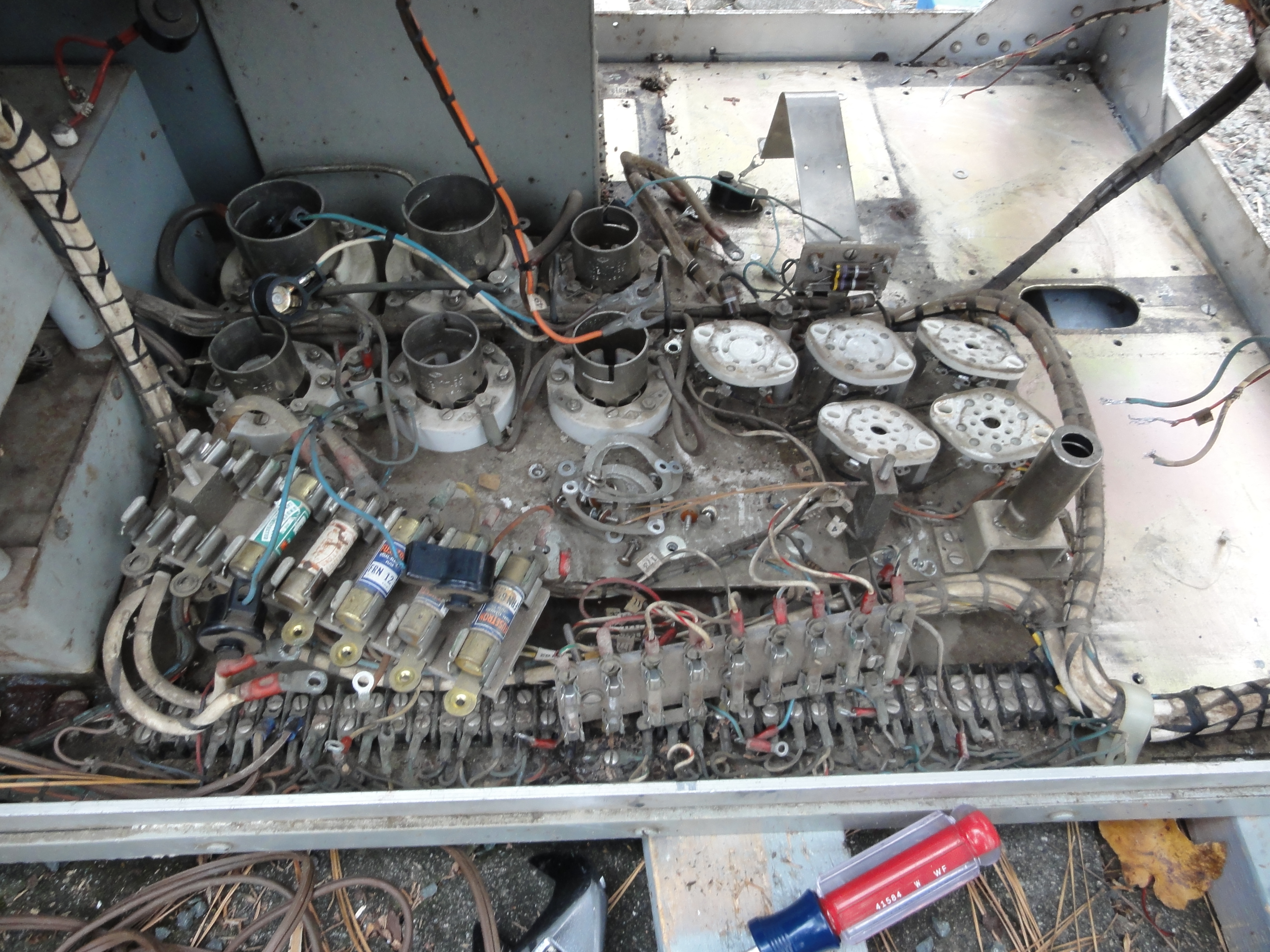
![DSC01562.JPG (4447846 bytes)](frt17/frt17-4/DSC01562_small.JPG) |
-- |
Before....
|
....and after
![DSC01566.JPG (4494082 bytes)](frt17/frt17-4/DSC01566_small.JPG)
|
>>>>>>>>
|
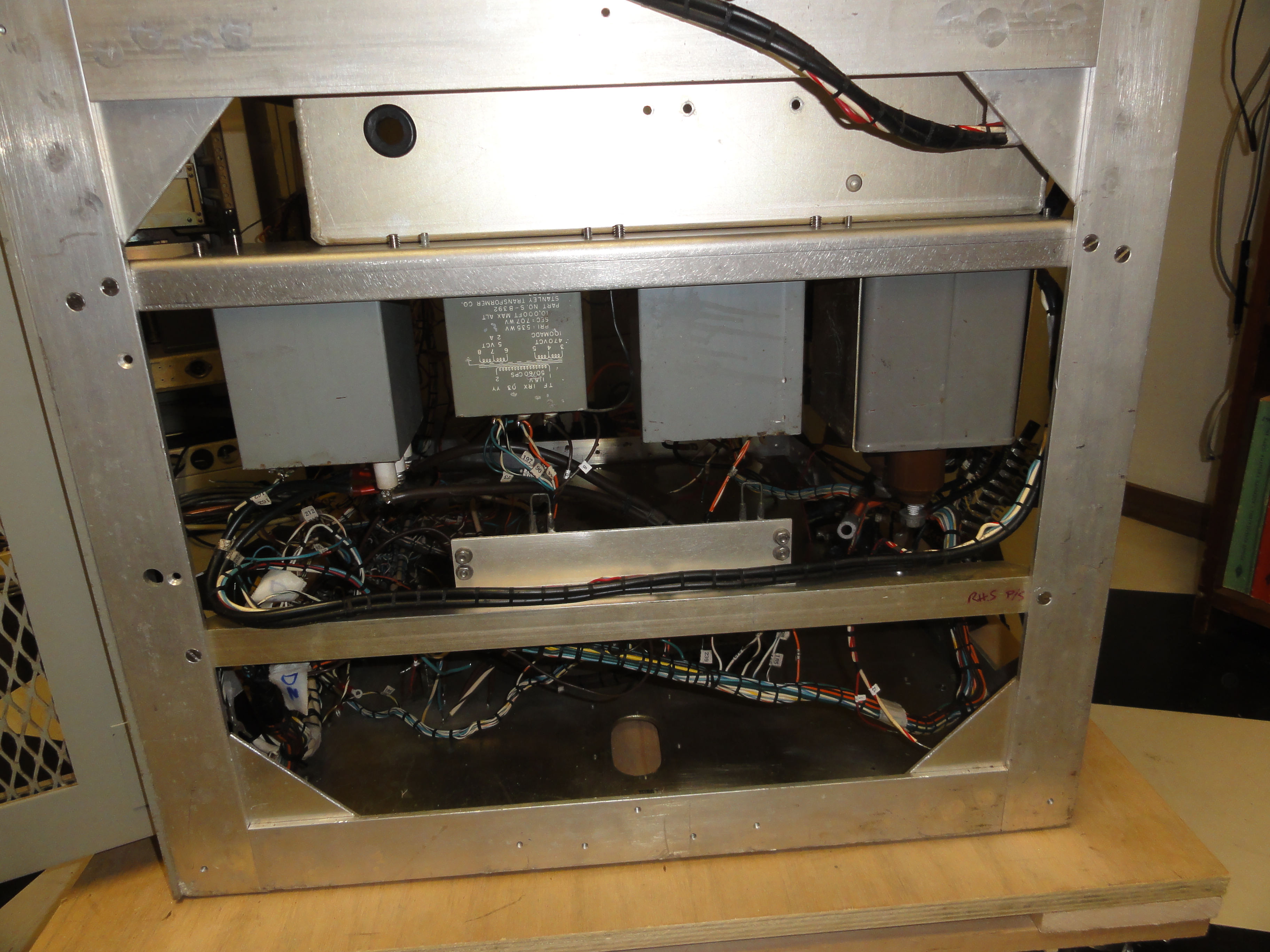
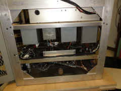
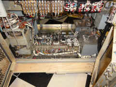
Completed power supply section (for now)
![DSC01567.JPG (4521457 bytes)](frt17/frt17-4/DSC01567_small.JPG) |
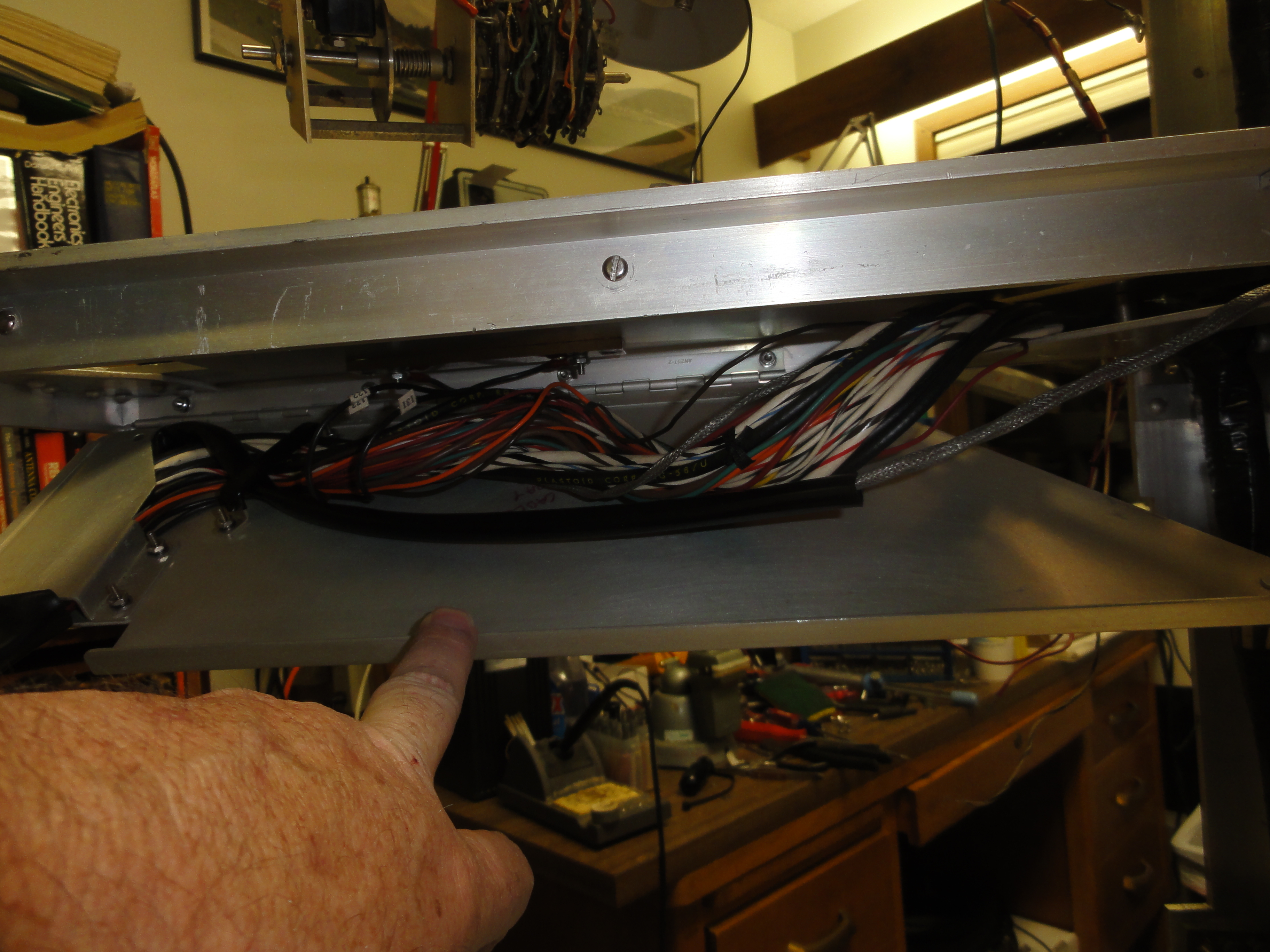
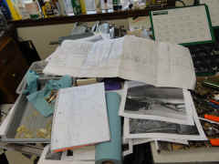
Figuring out where the drawer wiring harnesses were routed.....
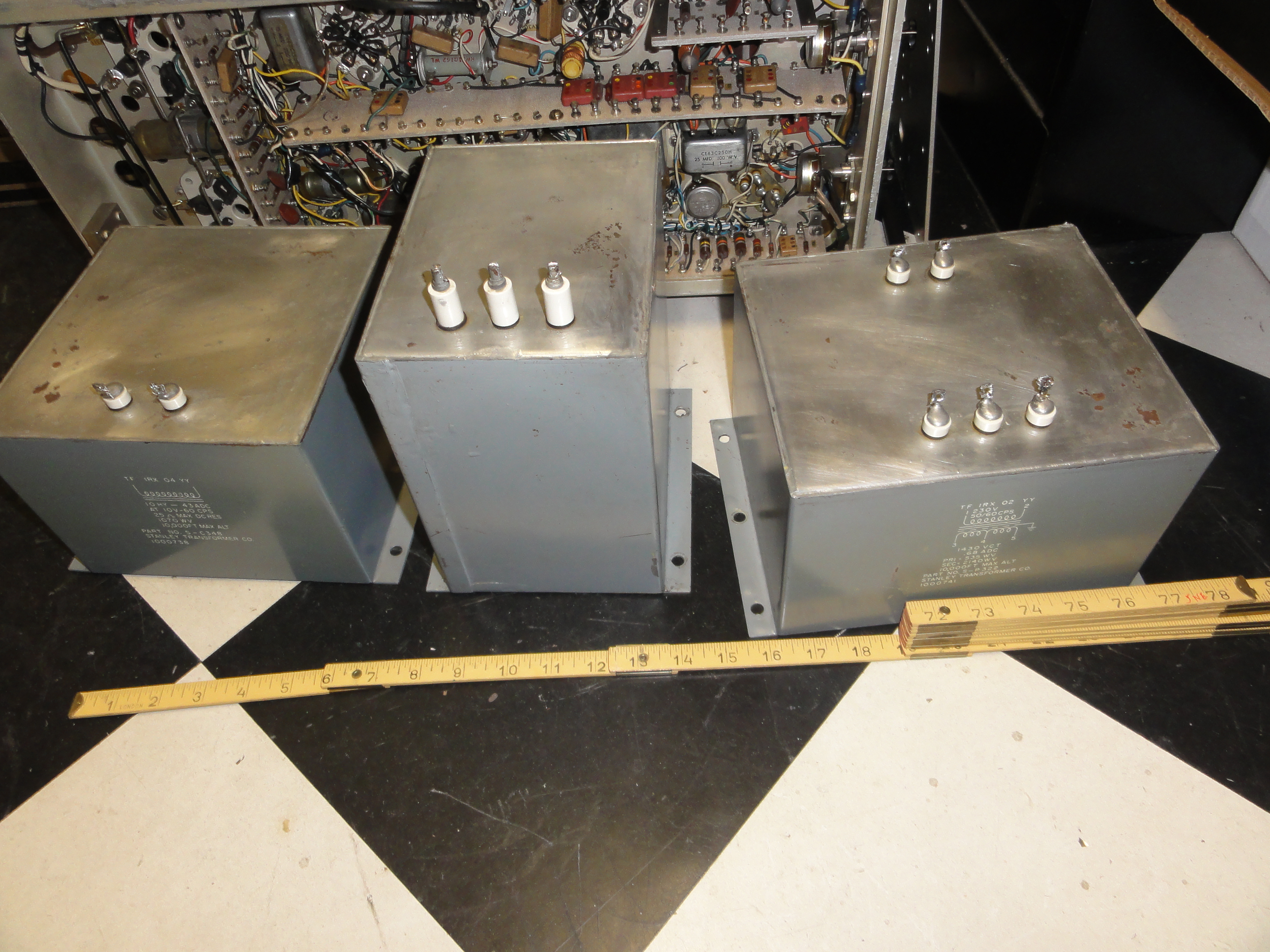
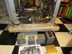
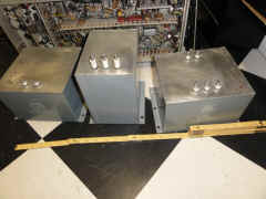
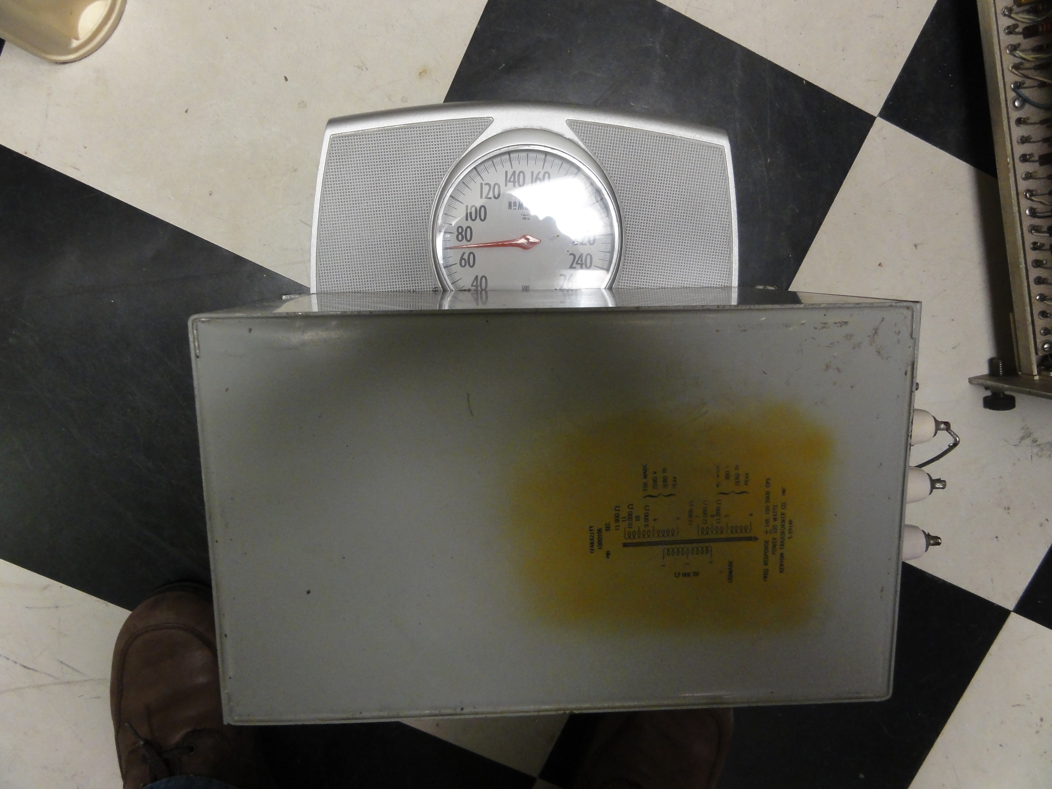
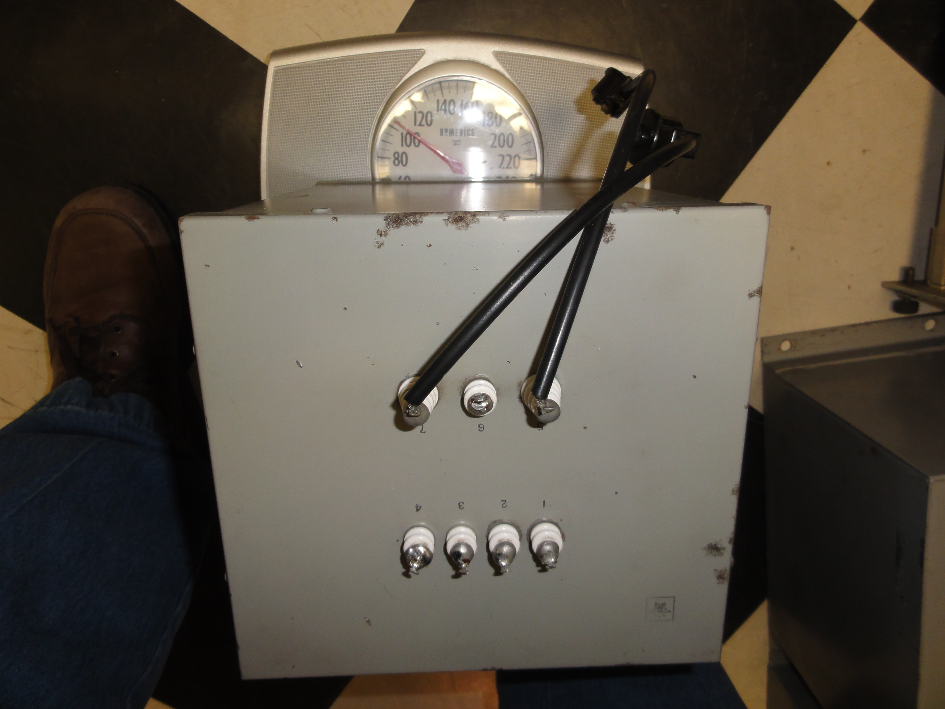
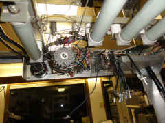
|
|
|
|
![DSC01572.JPG (3966474 bytes)](frt17/frt17-4/DSC01572_small.JPG) |
|
|
|
![DSC01576.JPG (4499866 bytes)](frt17/frt17-4/DSC01576_small.JPG) |
|
|
|
![DSC01587.JPG (4031070 bytes)](frt17/frt17-4/DSC01587_small.JPG) |
|
|
|
![DSC01591.JPG (4170538 bytes)](frt17/frt17-4/DSC01591_small.JPG) |
|
|
--
|
-- |
Mod xfmr - 70 lbs
|
Plate xfmr - 105 lbs
|
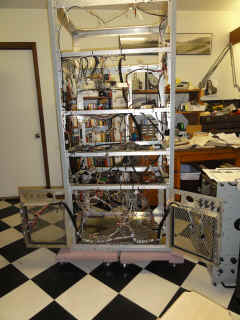
Everything back in place - with a little wiring left to do at the bottom
|
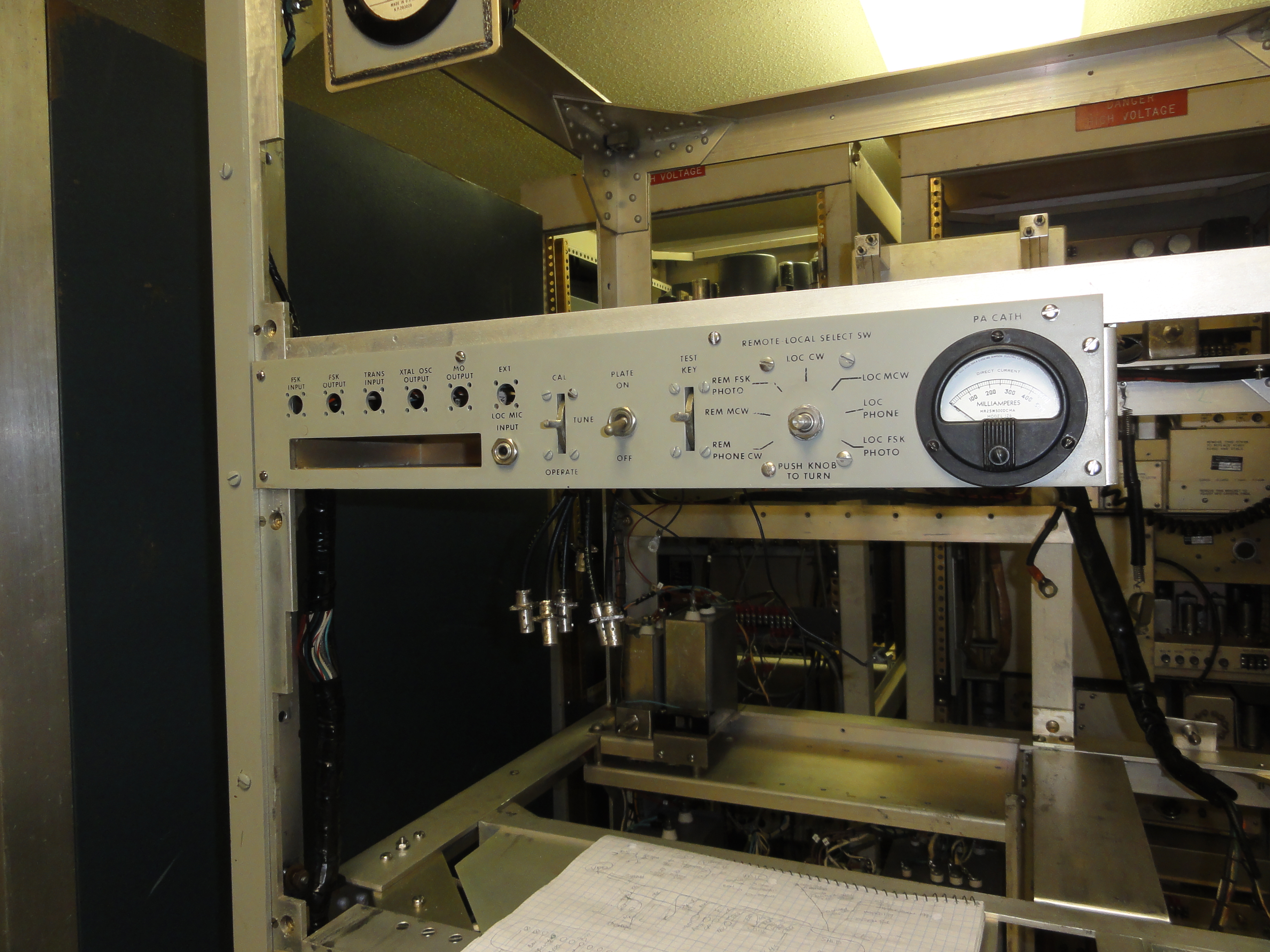
At last - Ready to start working on the drawers
![DSC01617.JPG (3590799 bytes)](frt17/frt17-4/DSC01617_small.JPG) |
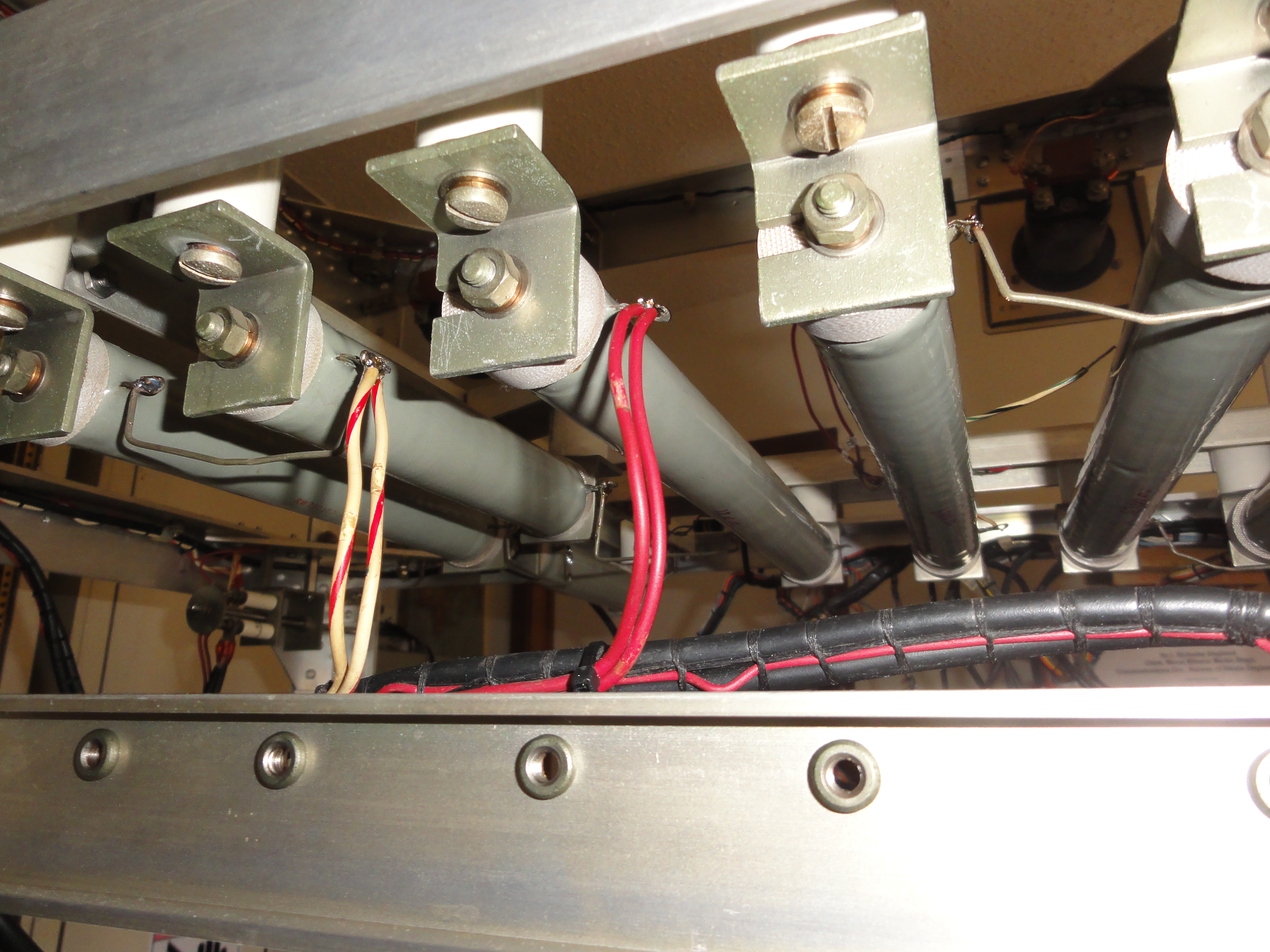
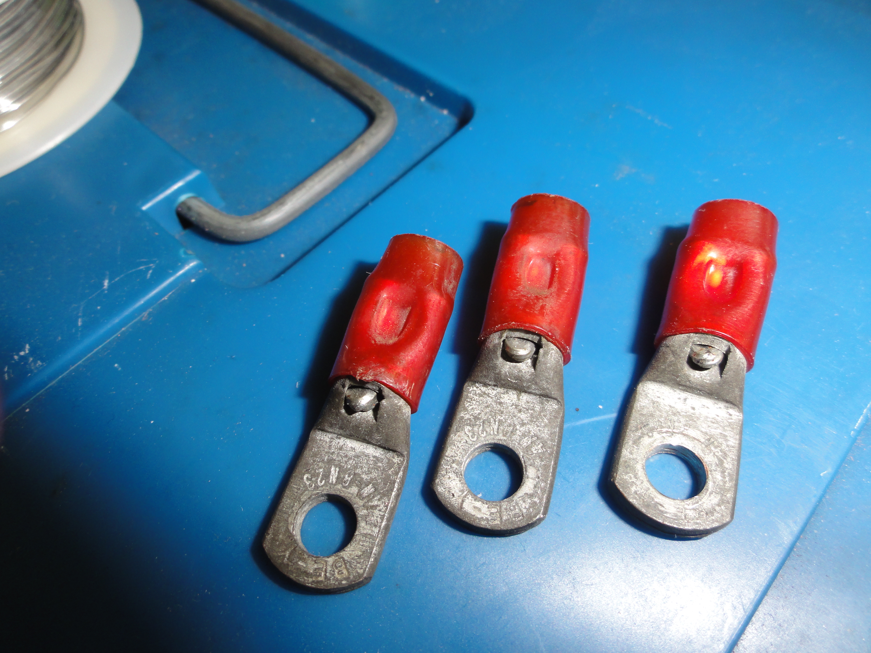
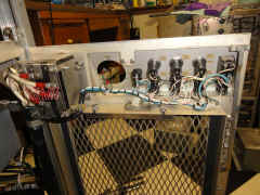
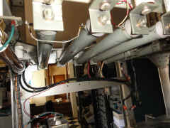
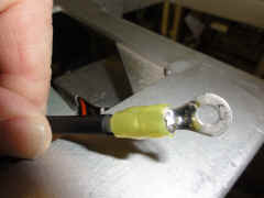
Big mistake - I didn't replace all these poorly crimped HV connectors when
I had the wiring harness out.
|
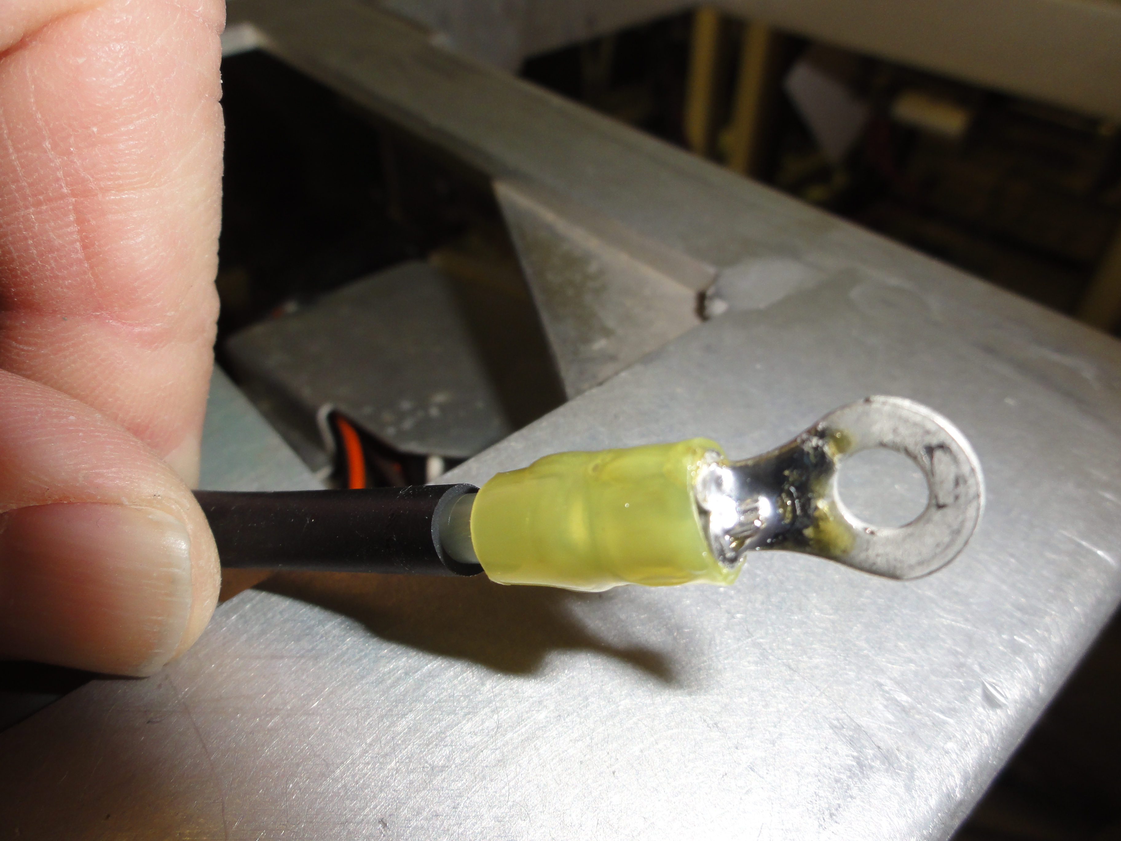
Nooo, I waited until everything was re-installed before deciding to solder
on new connectors
|
Some locations were easy to get to
|
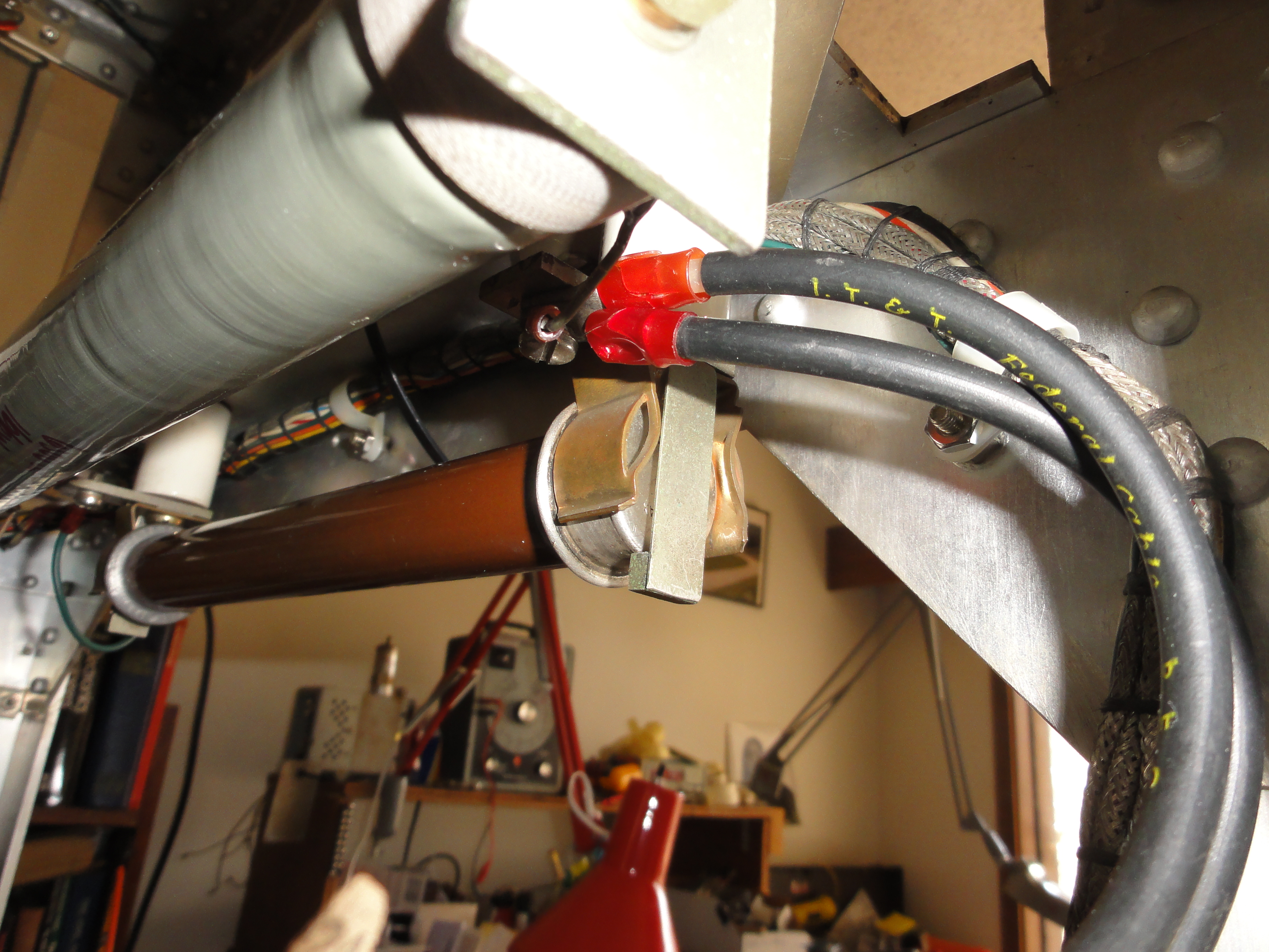
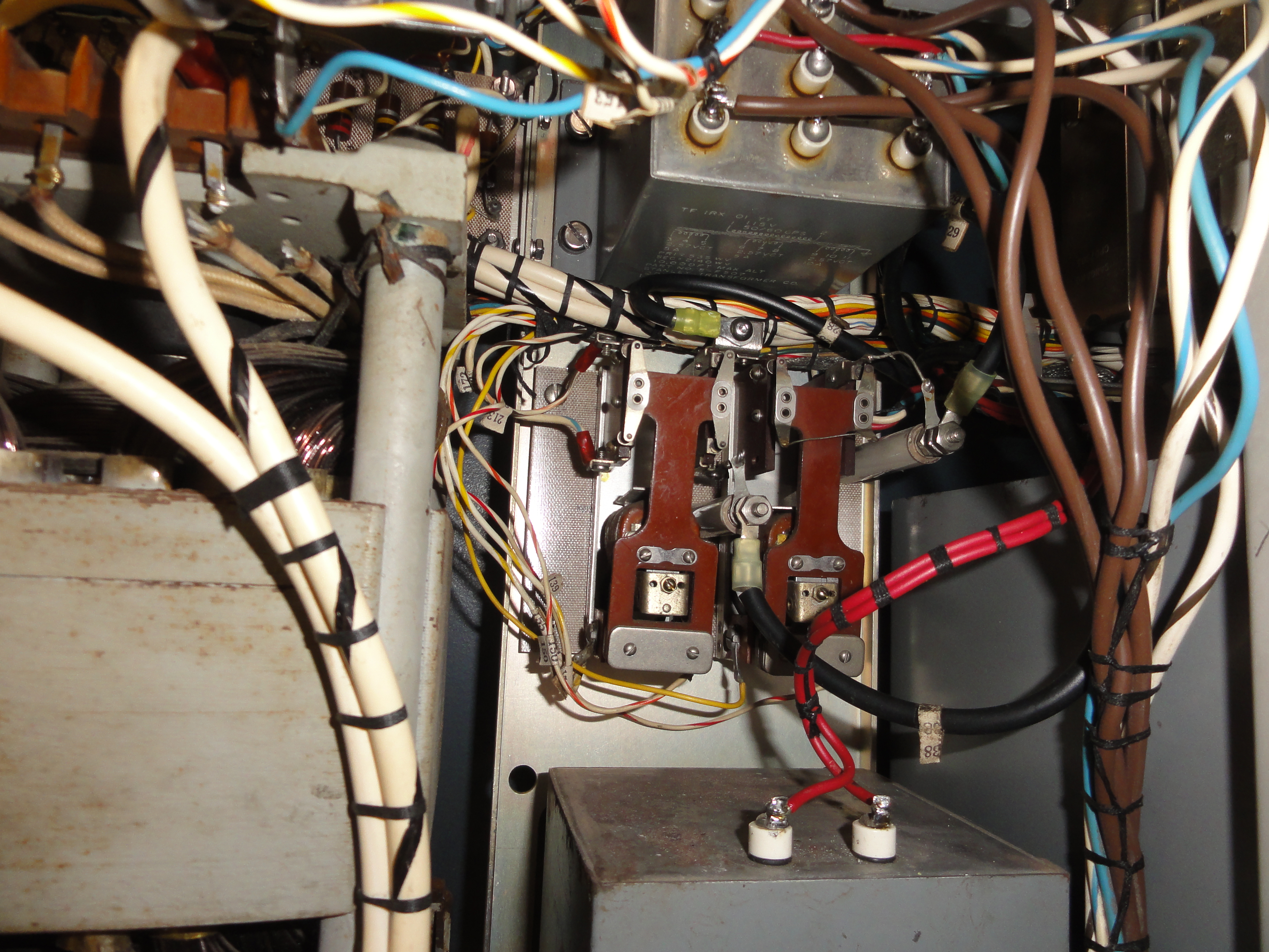
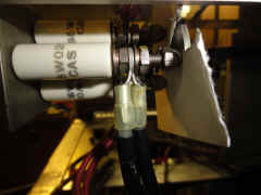
- and some of the terminals were MUCH more difficult to access.
![DSC01618.JPG (4325642 bytes)](frt17/frt17-4/DSC01618_small.JPG) |
Dang! Leftovers - I wonder where these were supposed to go.........
|
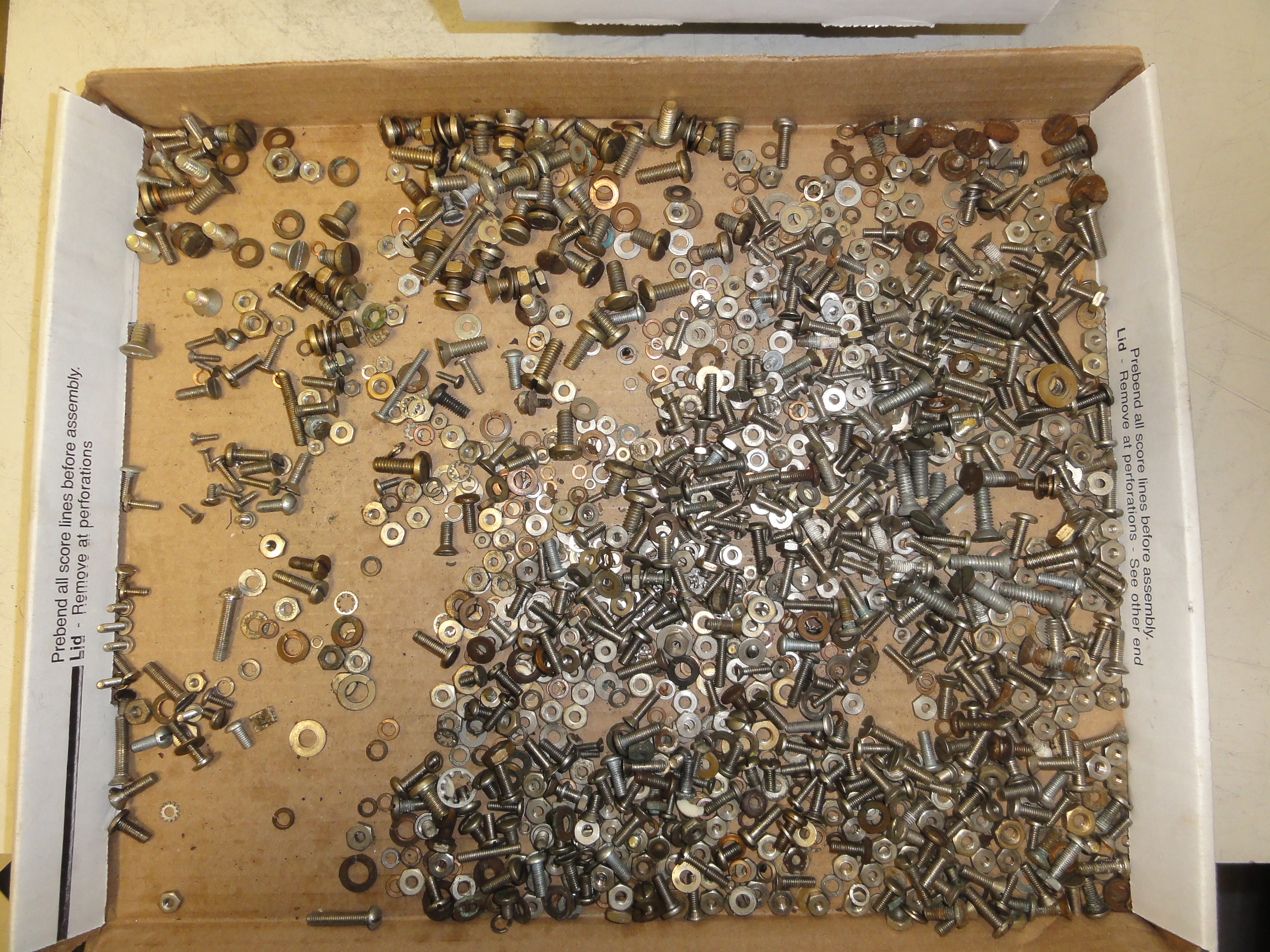
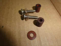
Corroded hardware that was replaced
|
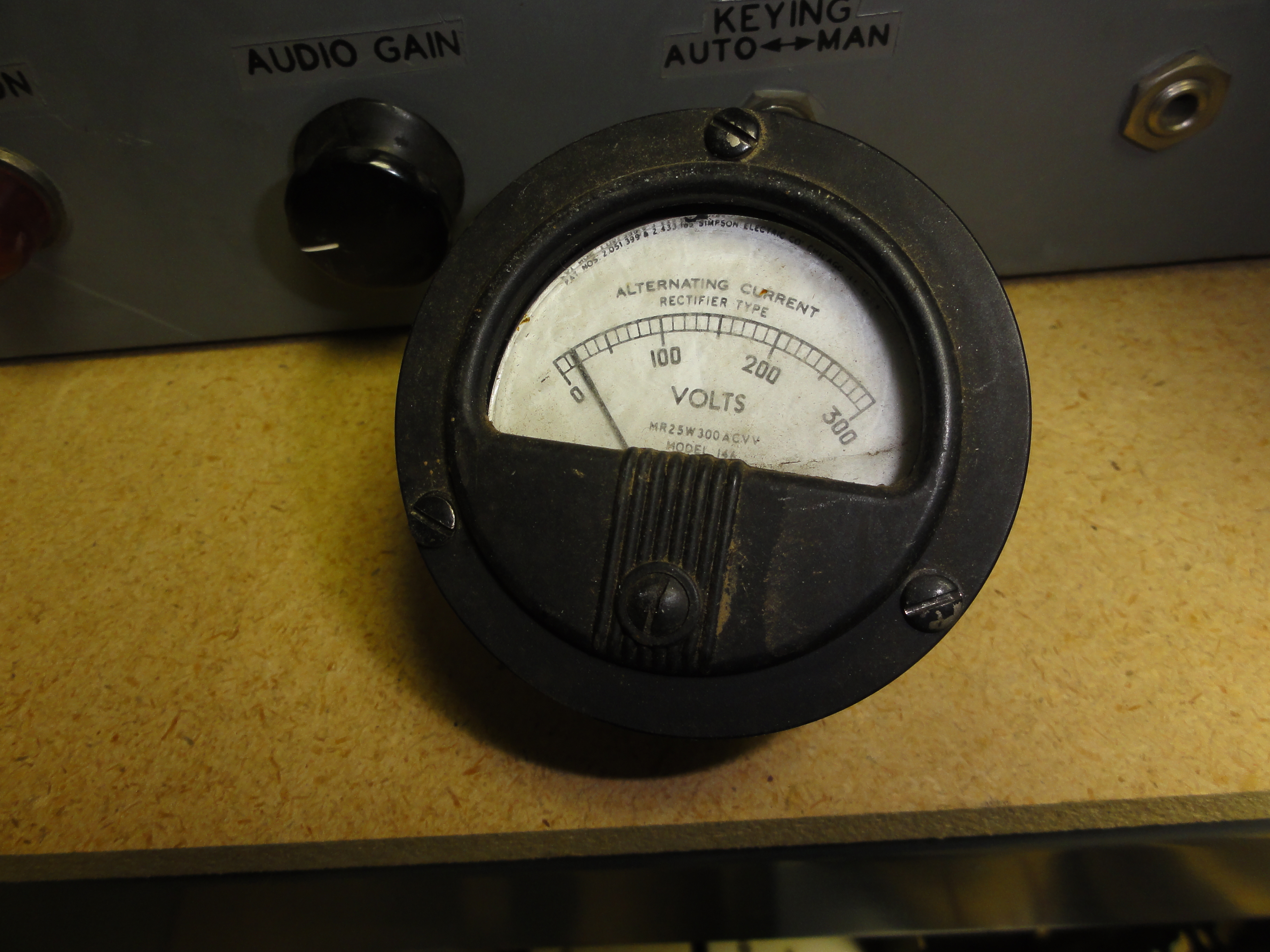
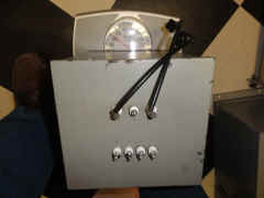
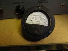
Still need to repair the meter glass
|
-- |
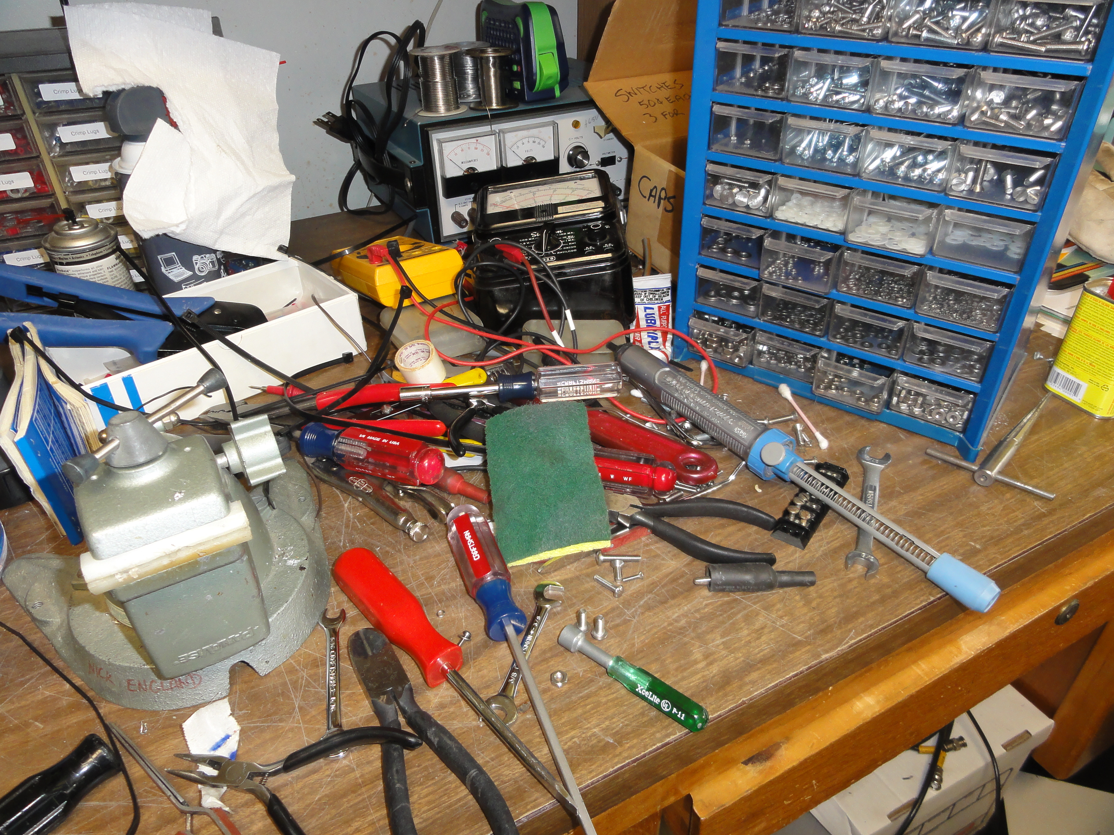
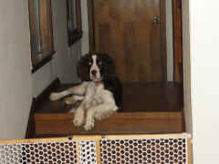
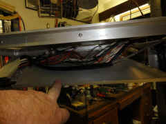
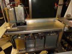
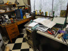
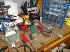
My working environment
|
|
|
|
![DSC01580.JPG (4470330 bytes)](frt17/frt17-4/DSC01580_small.JPG) |