
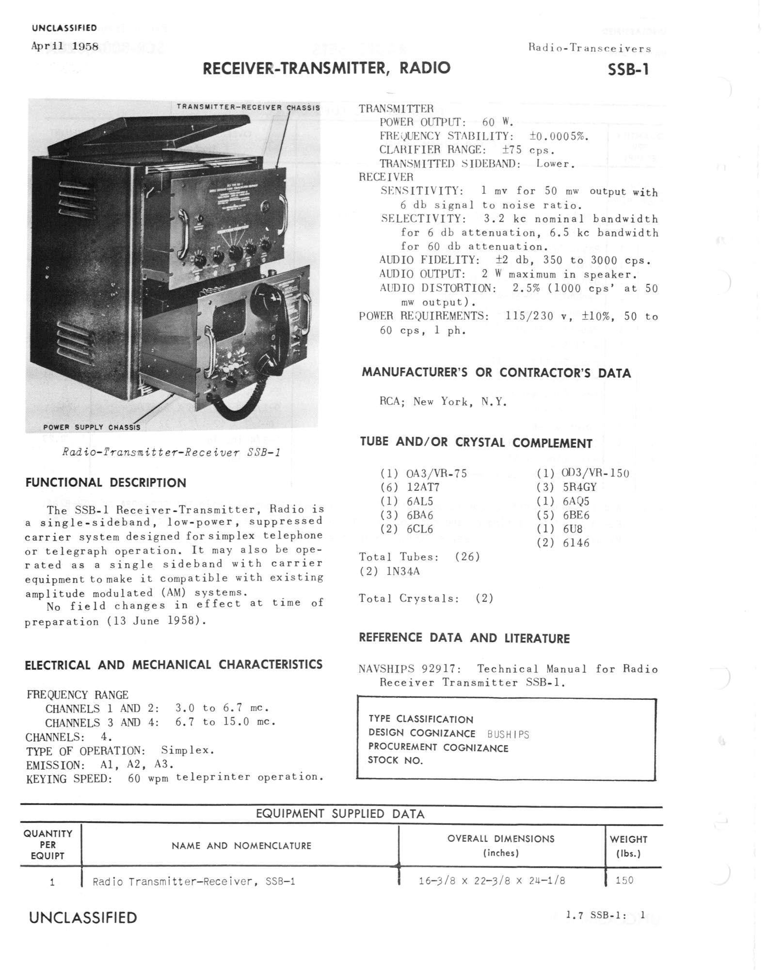
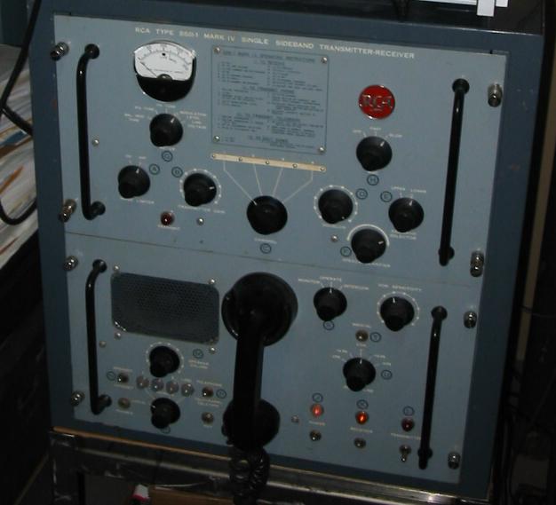
There were several variants of the SSB-1 - The NAVSHIPS 92917 manual covers the original version (it doesn't say Mk I) so presumably this is the first version used by the Navy. I have a Mk IV unit with Navy property tags as well. - Please e-mail me with any info or additional photos. Thanks
Commercial model from RCA used as an interim SSB transceiver until
replaced by AN/URC-32, etc. - see info below. Navy also used Eldico S-100
transceiver.
60 watts, LSB only, 3-15 mc, two 6146's in output.
250kc and 1400 kc IF's.
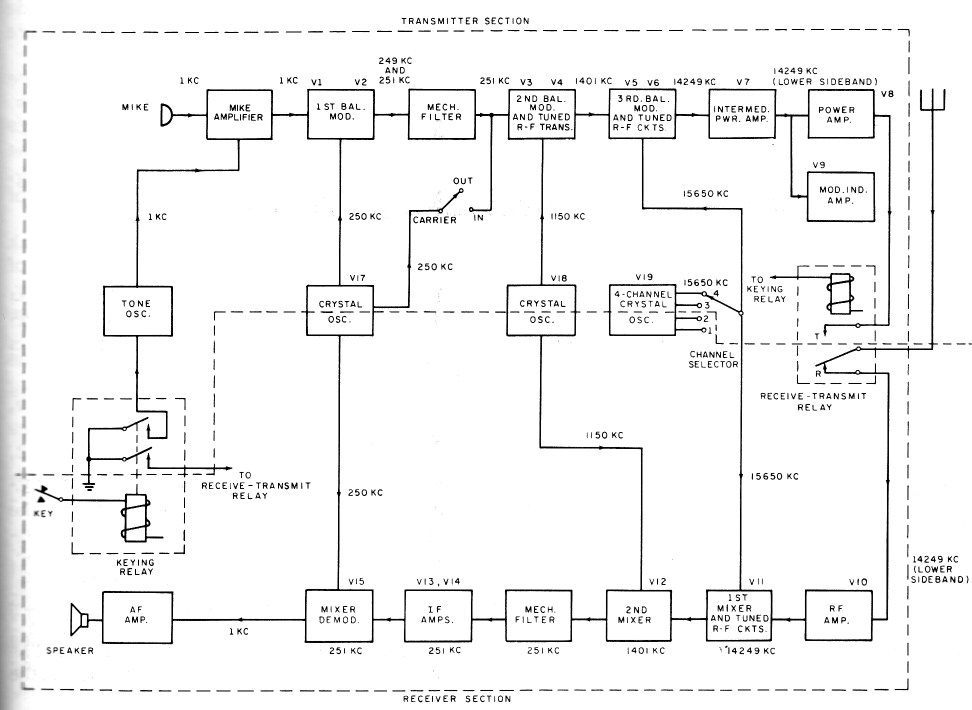
See block diagram below for signal flow.
Uses 3 kc wide mechanical filters in the 250kc IF.
Crystal-controlled - four channels - crystals are 1400 kc above desired frequency.
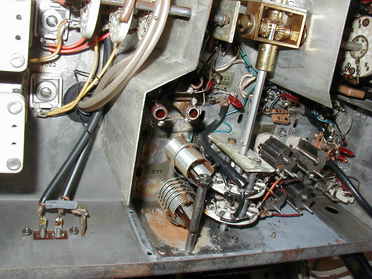
The channel selector switch selects the following:
crystal, rcvr RF amp tank, rcvr 1st mixer tank, xmtr 3rd balanced mod. tank,
xmtr driver tank, final tank coil taps, final tuning cap, final loading coil
taps.
In 1958 the U.S. Navy became interested in SSB. Initial tests were conducted on ships using mostly Collins Radio available amateur equipment. There were 16 ships, as I recall, outfitted and used in air defense exercises to prove the advantage over the then used CW/AM circuits. Twenty-Four hour tapes on the side-by-side circuits proved the overwhelming advantage of SSB communications.
The Bureau of Ships project searched for suitable and temporary use of equipments that were available until military equipment (AN/WRC-2, AN/URT-23, AN/URC-32, AN/URC-35, R-1051/URR) could be designed, produced and installed.
The only near suitable commercially available equipment was the RCA SSB-1. This was selected, procured and installed primarily on combatant ships to provide the SSB capability. The intent was to fix-install in the ship's wheel house. When it was determined that a location was to be in CIC or other selected areas, the problem became apparent for the need of a remote antenna tuner. The AN/SRA-20 was quickly designed and produced in a short time to meet the need.
The intent for use was for the equipment to be set up on the four crystal-controlled channels and not changed. These commercial equipments were not ruggedized for the frequent channel changing that fleet operations employed causing equipment casualties. This commercial equipment could not withstand the frequent channel changing requiring crystals and the retuning of screwdriver components.
The SSB-1 was removed from ships when the more ruggedized military equipment became available and then provided to Naval Reserve units for their use.
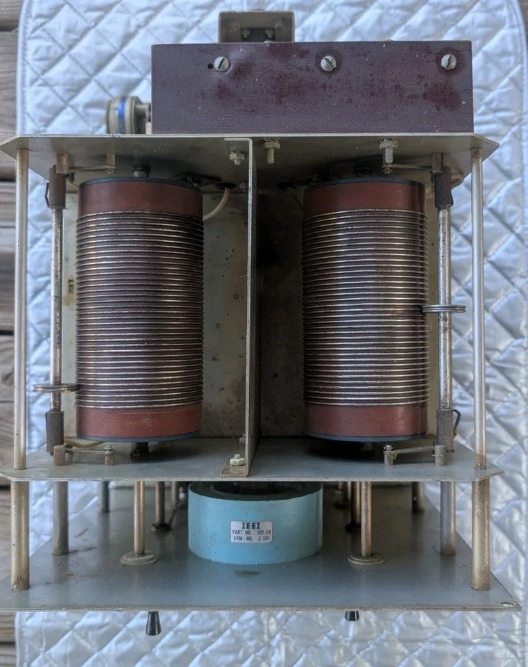
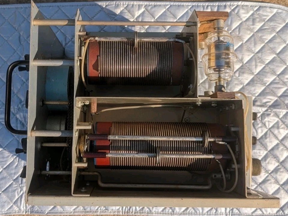
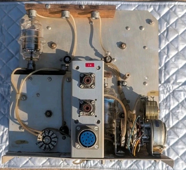
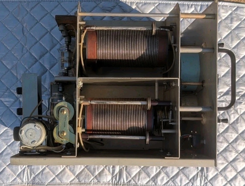
AN/SRA-20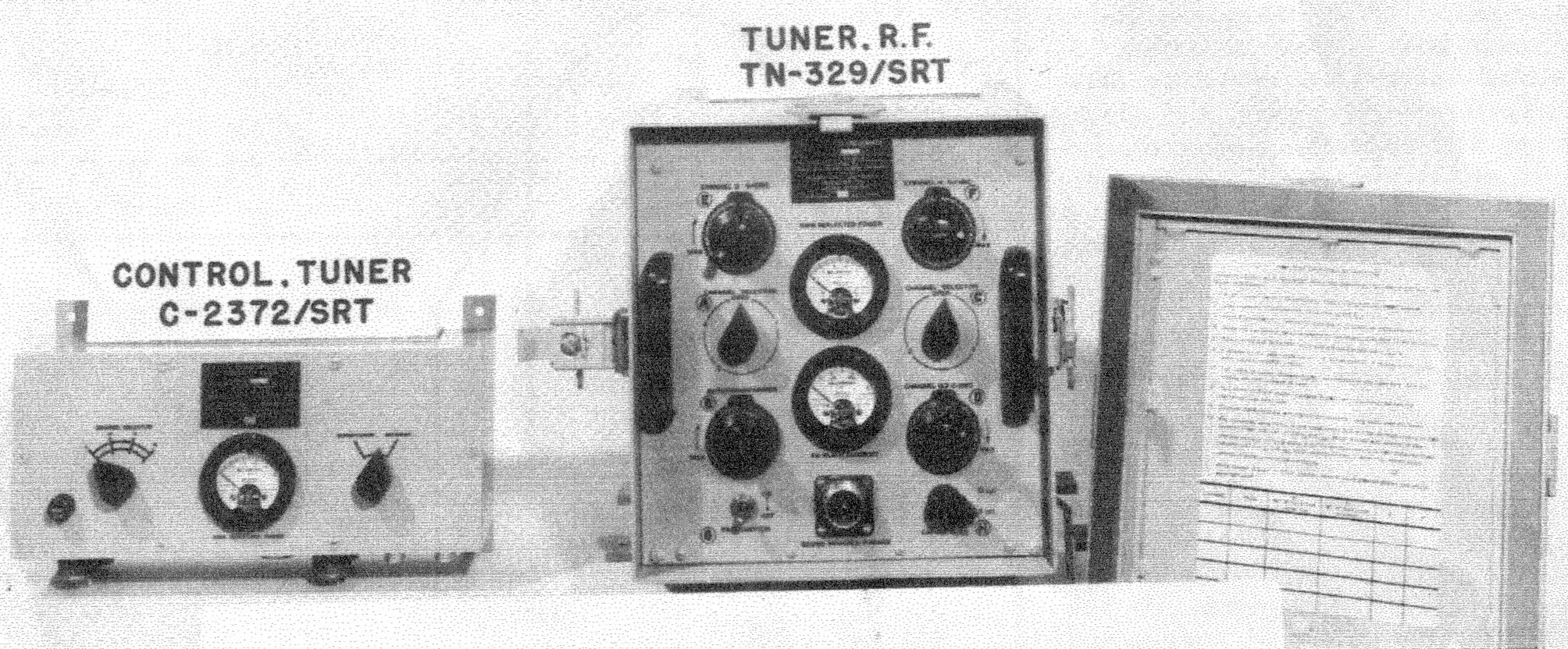 |
C-2372/SRT controller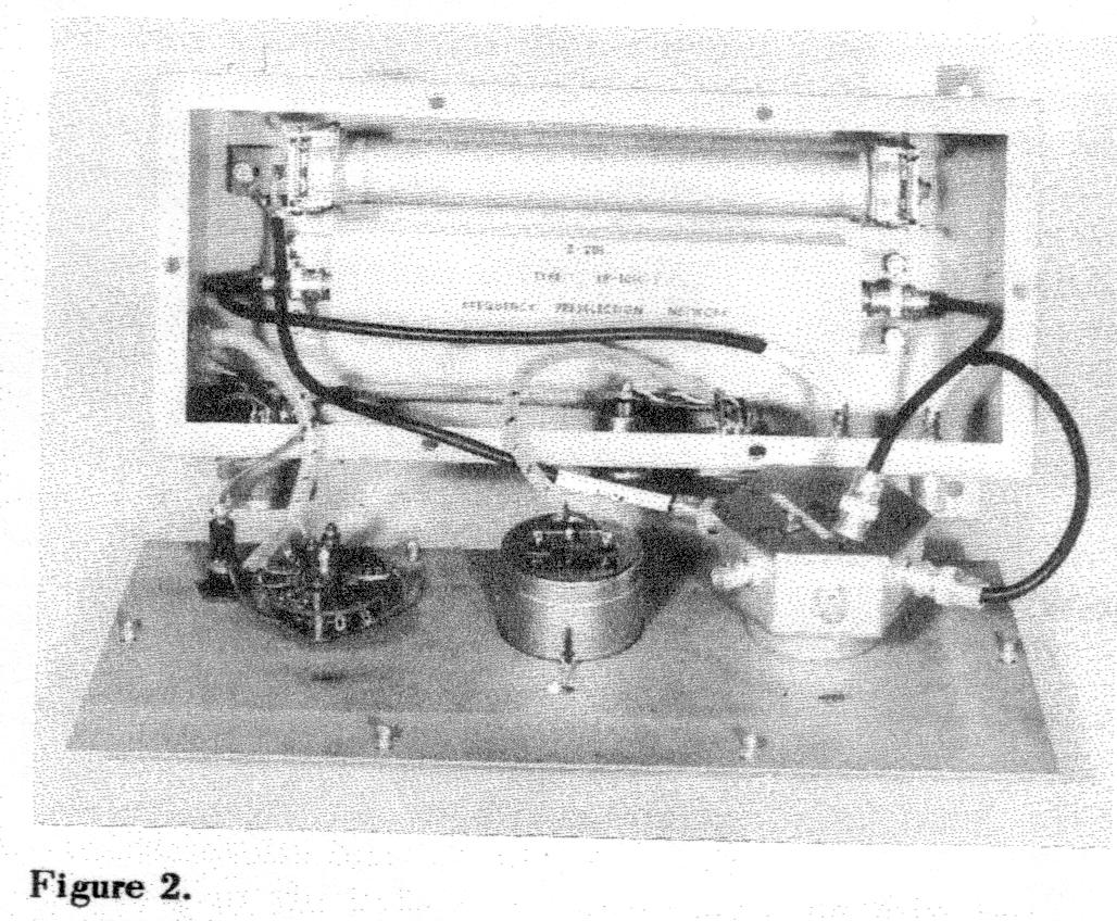 |
TN-329/SRT tuner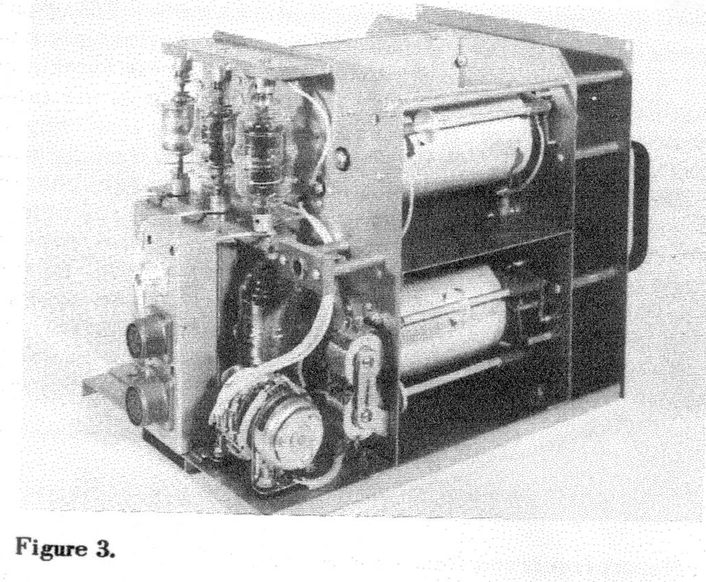 |
 |
 |
 |
 |
 |
 |
The antenna tuning group AN/ SRA-20 has been procured to eliminate antenna difficulties experienced with the transceiver RCA model SSB-1. A similar antenna tuning group is being developed for use with the Eldico S-100 single sideband equipment.
The SSB-1, a commercial equipment, was procured by the Navy to provide an immediate single sideband capability for nearly all ships. Though not specifically designed for naval shipboard use, this equipment has gained wide acceptance by the forces afloat.
The major discrepancy of the single sideband installations has been the inability to provide a satisfactory antenna and transmission line system. For this reason, the Bureau of Ships investigated and developed antenna tuning group AN/SRA-20. The AN/SRA-20 is provided as field change 2 to the SSB-1.
Development of the AN/SRA-20 by International Electronic Engineering Company began in November 1957. After numerous engineering tests, a technical and operational test was conducted on the USS Des Moines (CA-134). Because an antenna tuner was urgently needed, procurement action for the AN/ SRA-20 was initiated as soon as the Des Moines tests were completed.
The antenna tuner provides a means of matching a 35-foot whip to a 50-ohm transmission line in the frequency range of 2 to 15 megacycles. The tuner can be used with transmitters rated up to 100 watts (average power). The insertion loss is less than 0.5 decibel and the power required is 115 volts, 60 cycles, single phase, 100 watts. The power is necessary only during the period of equipment channeling operations.
The AN/SRA-20 consists of two units shown in figure 1, namely:
- Control tuner C-2372/SRT
- Tuner, RF TN-329/SRT
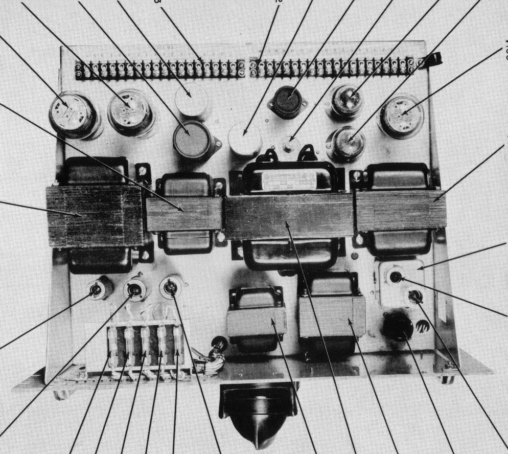
Figures 2 and 3 are interior views of the C-2372/SRT and TN-329/ SRT. The
C-2372/SRT control unit contains a 120-watt antenna dummy load which can be selected by a front panel switch, a 2-30
megacycle bandpass filter, a SWR meter, an auxiliary tuner channeling switch, and a sound-powered telephone receptacle.
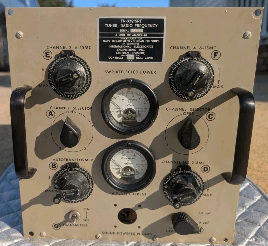
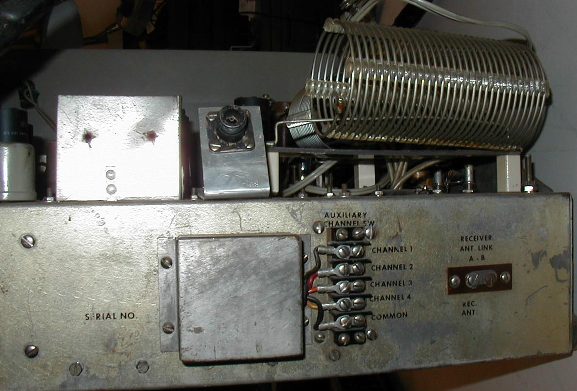
The TN-329/SRT tuner contains all the electrical circuitry and mechanical parts for the operation of the tuning elements. The tuner provides for presetting four individual channels and for matching the 50-ohm transmission line to a standard Navy 35-foot whip or longer antenna. The preset channels are selected remotely and simultaneously by the transceiver SSB-l. Parts are supplied with the field change for modifying the SSB-1 to provide this capability.
In addition, the tuner contains a SWR meter, a transmitter plate current meter, a transmitter keying switch, and a sound-powered telephone receptacle which is used in the antenna tuning process. The field change kit also contains a plate current meter for installation in the SSB-1 equipment.
The field change bulletin for modification to the SSB-1 is included with the AN/SRA-20.
The applicable Bureau of Ships installation outline plan is RE 47F2012. The technical manual is NavShips 93202.
By Fred Chapman
Communication Section, Bureau of Ships
As a result of recent technological advances in the communications field, the use of the single sideband mode of transmission and reception is growing.
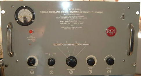
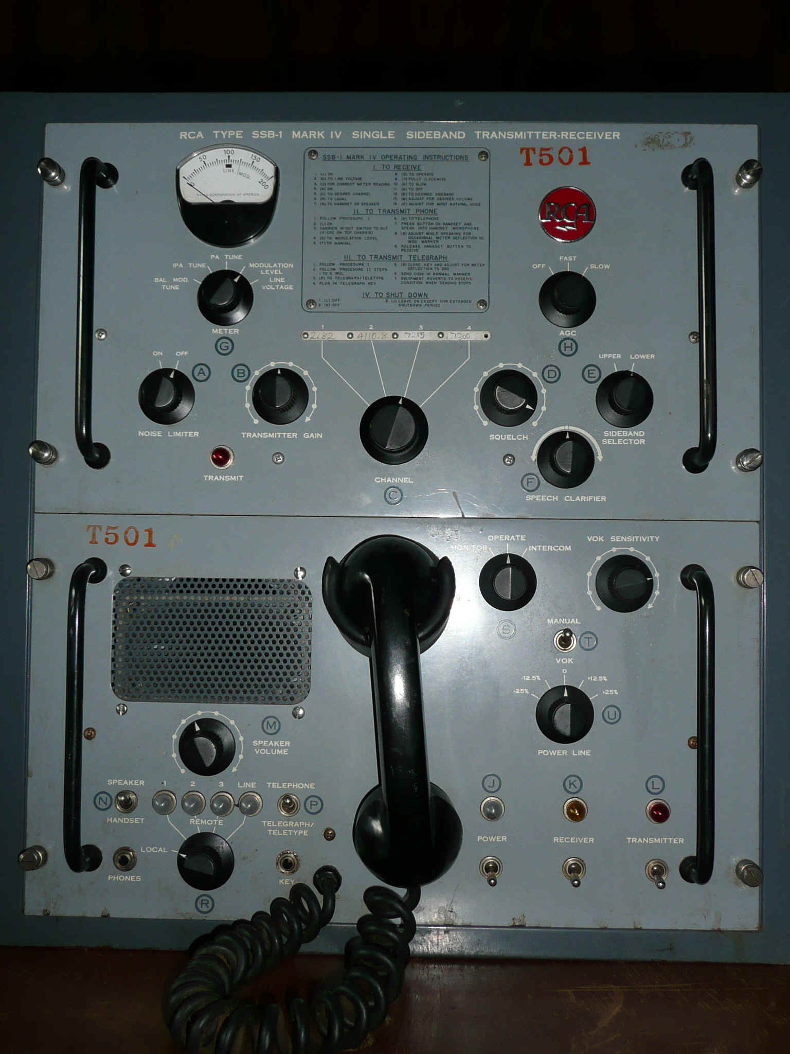
The desire to increase present naval communications capabilities and to keep abreast of modern trends has led to the procurement of commercially available single sideband equipment. This equipment was procured to fill the gap until equipment specifically designed for shipboard use is available. The commercial equipments procured include the Eldico transmitter-receiver and the RCA model SSB-1. This article describes the latter (figure 1).
Basic Principles
In a conventional amplitude-modulated (AM) system, the radiated signal includes a carrier, an upper
sideband, and a lower sideband. All the intelligence is contained in the sidebands, none is in the
carrier. Therefore, there is no need to transmit the carrier if it can be inserted at the receiving
end. Furthermore, since both sidebands contain identical and complete information, only one need be
transmitted.
In a standard AM system modulated 100 percent with a sine wave, 66 percent of the radiated power is in the carrier and 17 percent is in each sideband. The SSB-1 eliminates the carrier and the upper sideband from the transmitted signal, thus operating at the same intelligence power level with a possible saving of 83 percent of the total radiated power, as compared with a standard AM transmitter.
Advantages of Single Sideband, Suppressed Carrier Communication
The SSB-1 operates on a total frequency band width of approximately 2.8 kilocycles as opposed
to an equivalent AM system which operates on a frequency band of about 6 kilocycles. Figure 2
illustrates the frequency spread of each system.
In addition, this equipment transmits intelligence at a much higher level than that transmitted by an AM system of equivalent power. Figure 2 illustrates the relative power levels of the radiated intelligence of both systems.
Single sideband equipment is much smaller than comparable AM equipment, since less power is required. The transmitted signal is subject to less distortion, noise, and interference than AM signals, since the frequency bandpass is narrower.
Equipment Description
The SSB-1, a 60-watt (peak envelope power) single sideband, suppressed carrier
transmitter-receiver, is now being installed in many ships. Its use is primarily
for voice communications in the frequency range of 3 to 15 megacycles. The operating frequency
is selected from one of four pre-tuned channels and the signal is transmitted on the lower sideband
only.
The SSB-1 consists of a transmitter-receiver chassis and a power supply chassis mounted within a single cabinet for shelf-mounting.
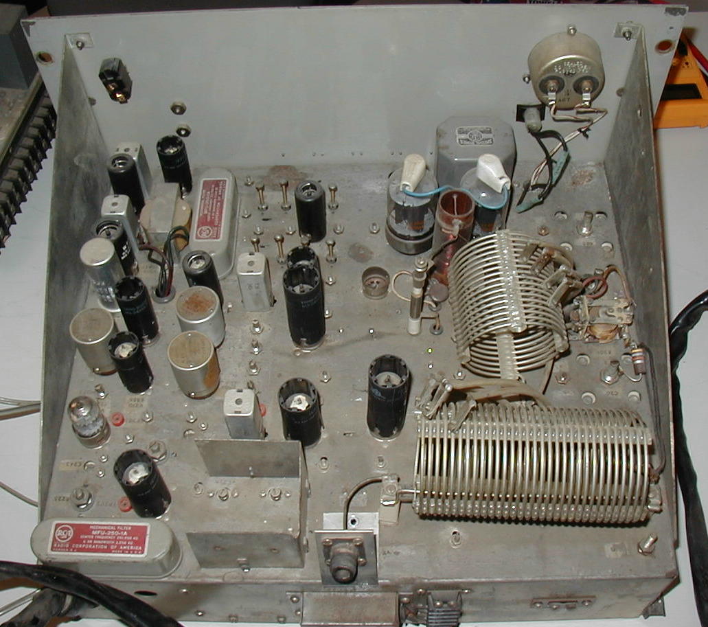
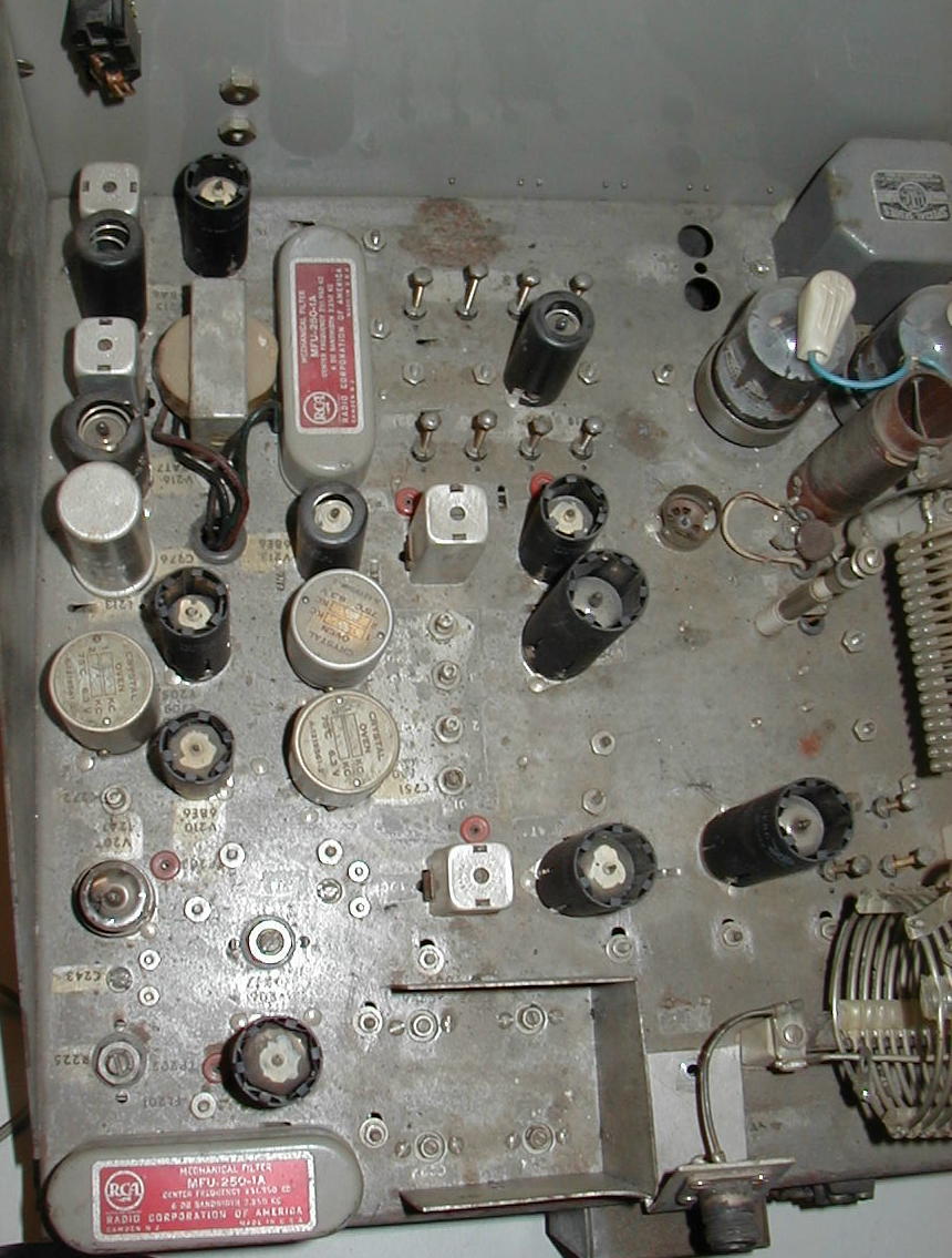
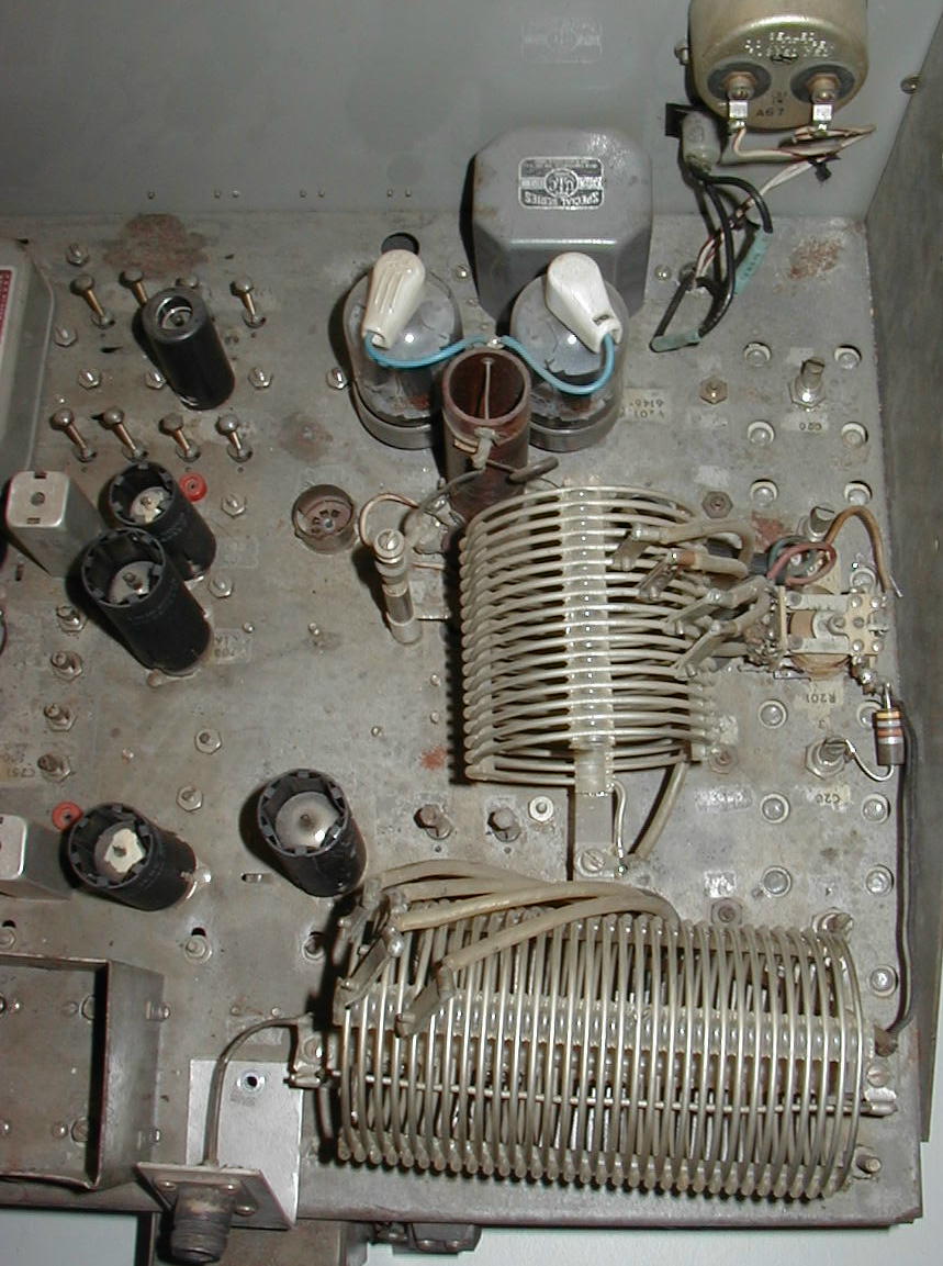
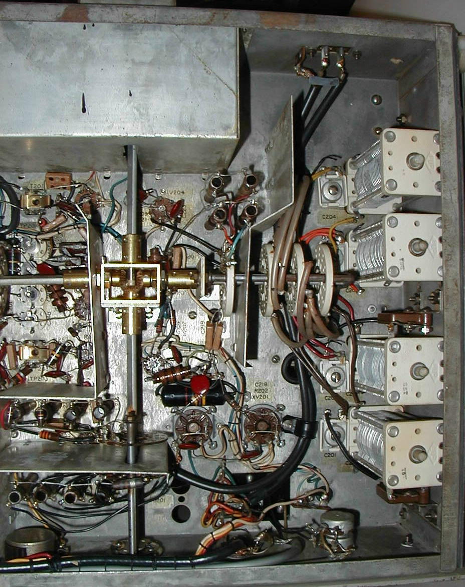
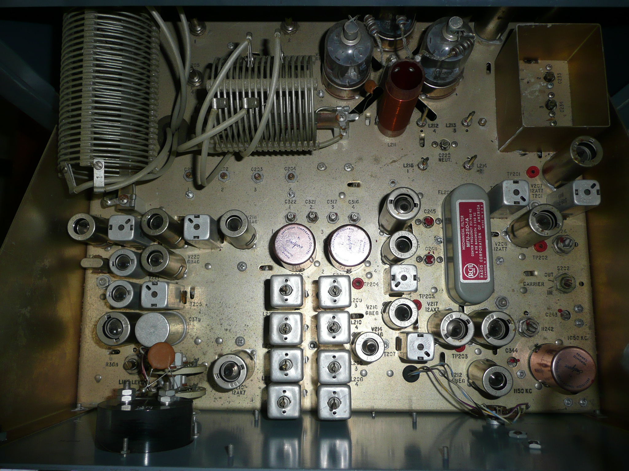
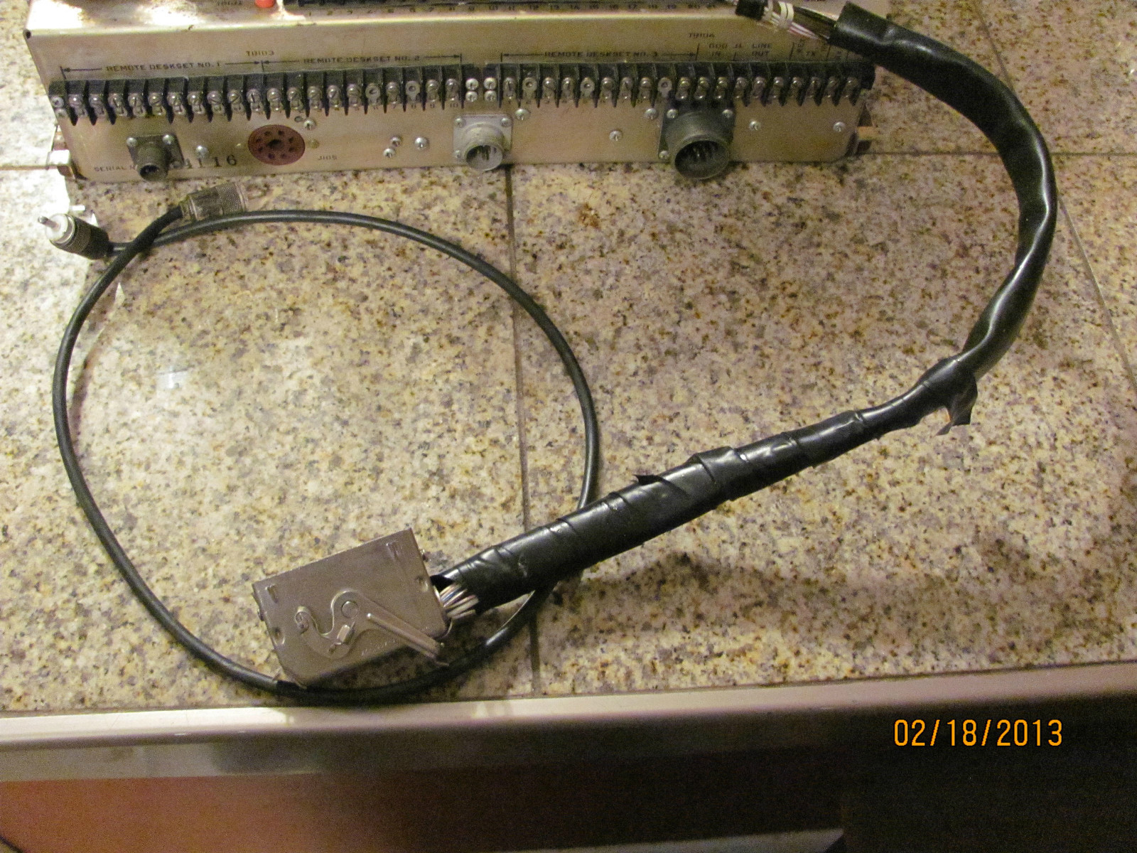
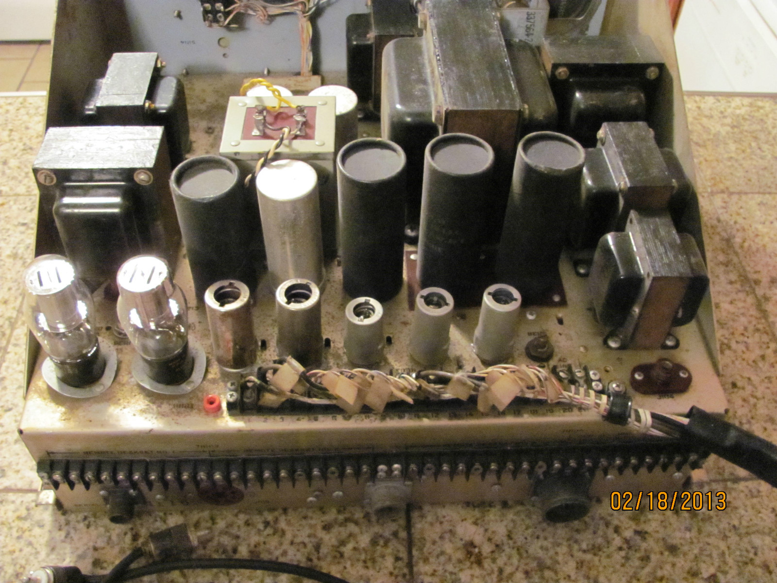
The overall dimensions are shown in figure 3- Access to the transmitter-receiver chassis for maintenance or equipment tune-up adjustments is through raising the top lid of the cabinet or withdrawing the two chassis (figure 4).
All circuitry is contained on the two chassis. The lower (power supply) chassis includes all power supply circuits, control circuits, the speech clipper, and all audio circuits except the receiver first audio amplifier. The upper (transmitter-receiver) chassis contains all the radiofrequency (RF) circuits plus the receiver first audio amplifier stage.
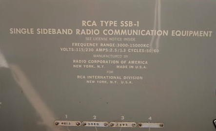
The equipment operates from either a 115-volt or 230-volt, 50- to 60-cycle single-phase power source and requires approximately 310 watts for full power output.
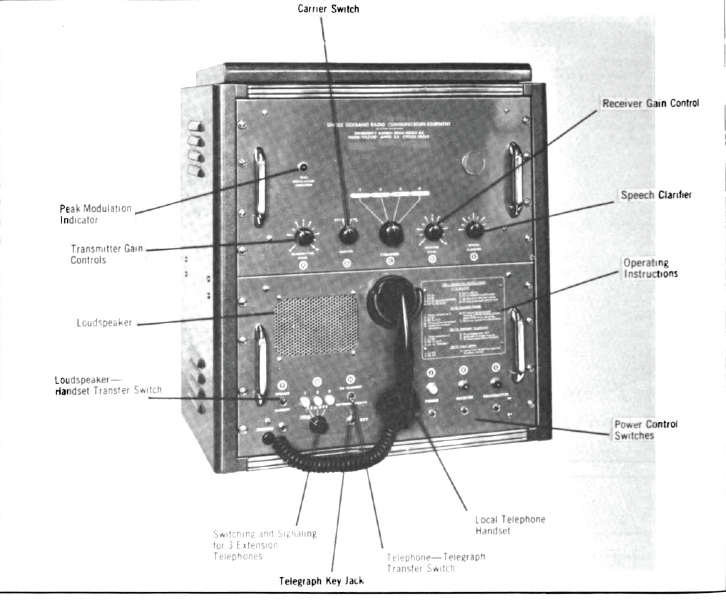
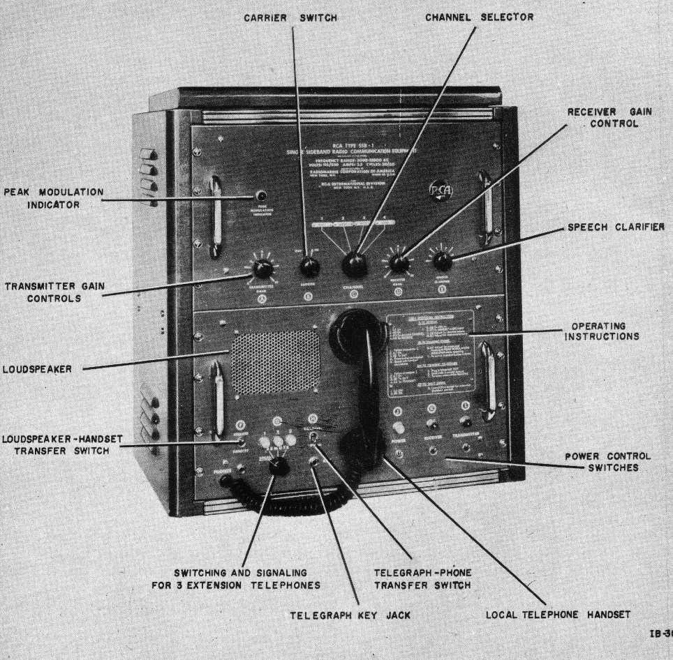
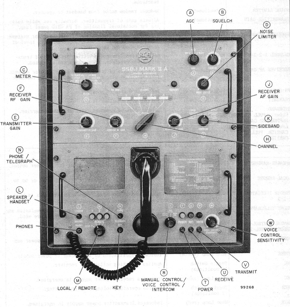
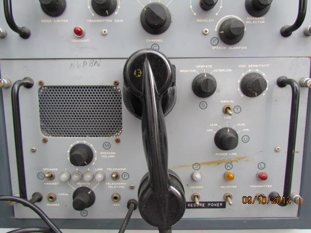
A block diagram of the equipment and locations of the front panel controls are shown in figures 5 and 6.
Although remote control operation from the ship's standard radio remote control system is not provided in the SSB-1, the Bureau of Ships is investigating a modification whereby this equipment may be thus controlled. The Bureau is also investigating the use of a linear amplifier for use with the SSB-1 to provide a higher power output when required.
Other investigations include those for a suitable shipboard type of antenna tuner.
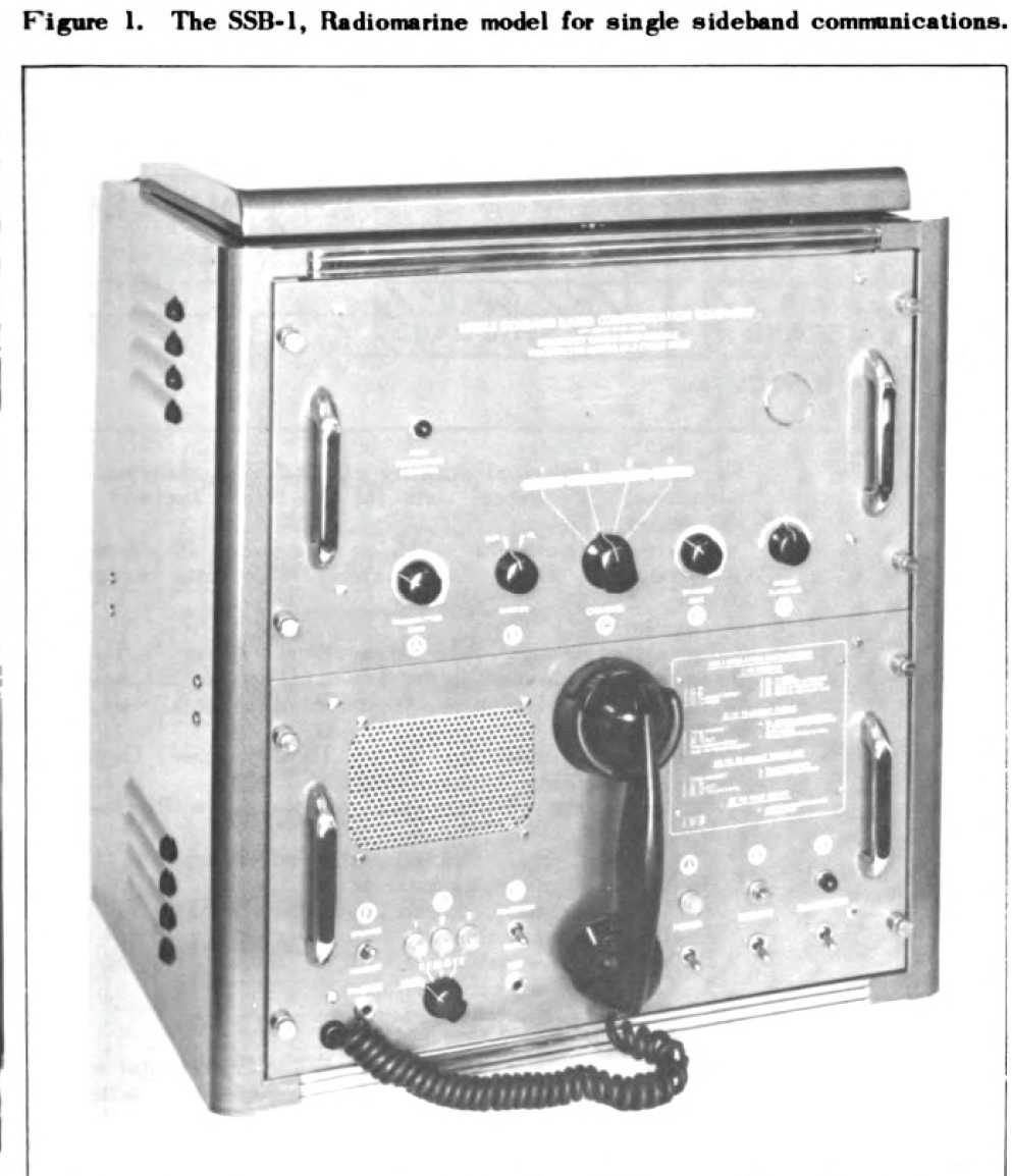 Figure 1. The SSB-1, Radiomarine model for single sideband communications. |
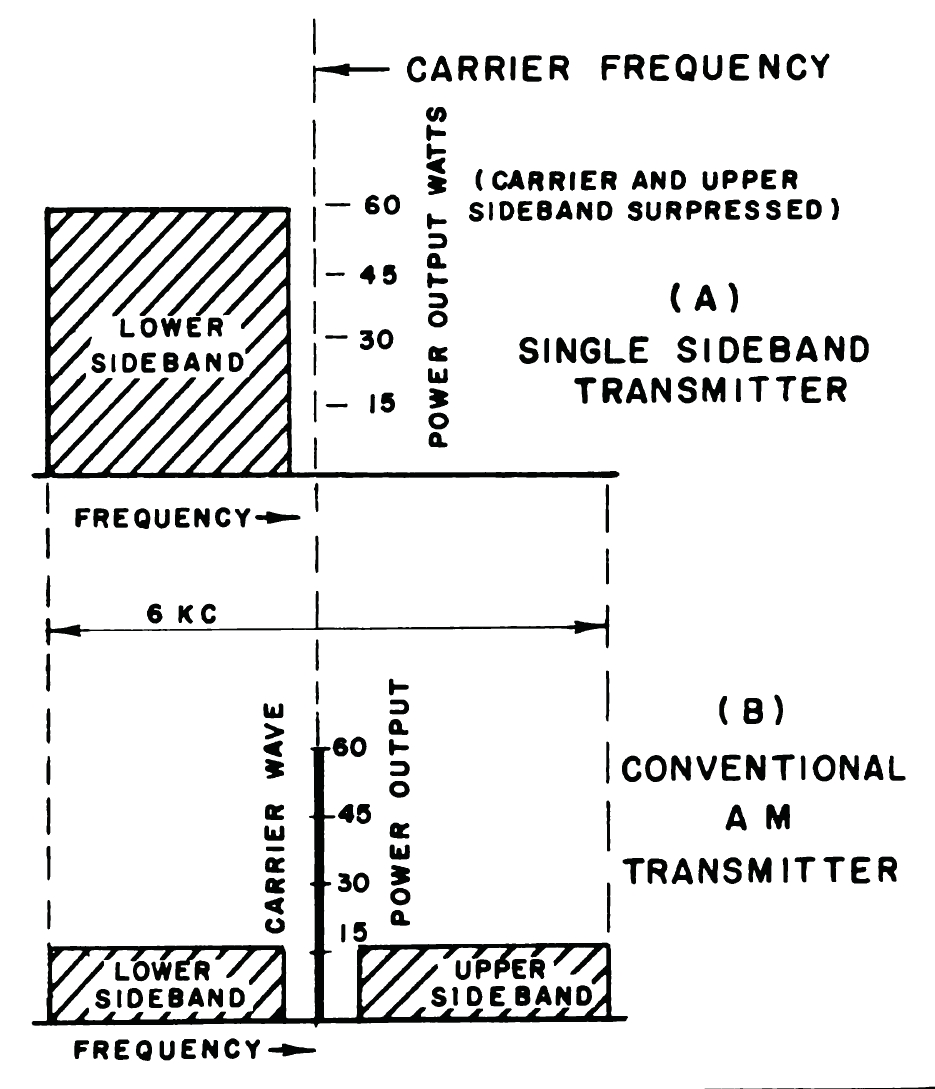 Figure 2. Carrier frequency of single sideband transmitter compared to conventional AM transmitter. |
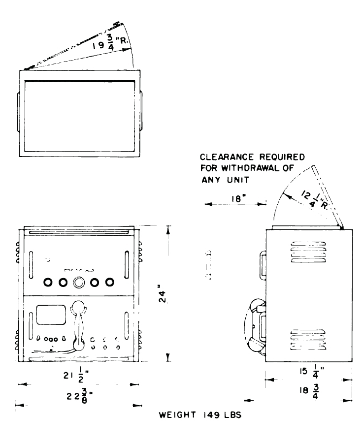 |
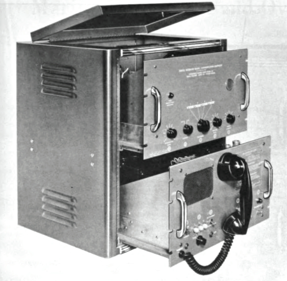 Figure 4. The SSB-1 showing arrangements for access. |
| Figure 3. Technical drawing of the SSB-1 showing dimensions. Technical data for the SSB-1 include the
following: Power requirements: 115 or 230 volts, 10 percent, 50-60 cycles, 310 watts (maximum) (85 watts receiver only). Channels: 4. Frequency range: 3-15 megacycles. Channels 1 and 2 have two frequencies in the 3.0- to 6.7-megacycle range. Channels 3 and 4 have two frequencies in the 6.7- to 15- megacycle range. Antenna required: Resistance, 10 to 80 ohms. Capacitance, 300 micromicrofarad (minimum). Power output: 60 watts (peak envelope power), lower sideband only. Audio input: Single button carbon microphone. Audio output: 2 watts maximum in speaker. Technical manual: Instruction Book: NavShips 92917. Test equipment required: 1. Vacuum tube voltmeter with RF probe. 2. Calibrated signal generator. 3. 0-250 ma. d.c. milliammeter. 4. Oscilloscope. 5. Dummy antenna: 75-watt non-inductive resistor with a resistance between 10 and 80 ohms in series with a transmitting type of capacitor of at least 300 micromicrofarads. |
|
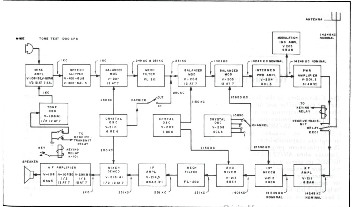 Figure 5. Block diagram of the SSB-1. |
 |
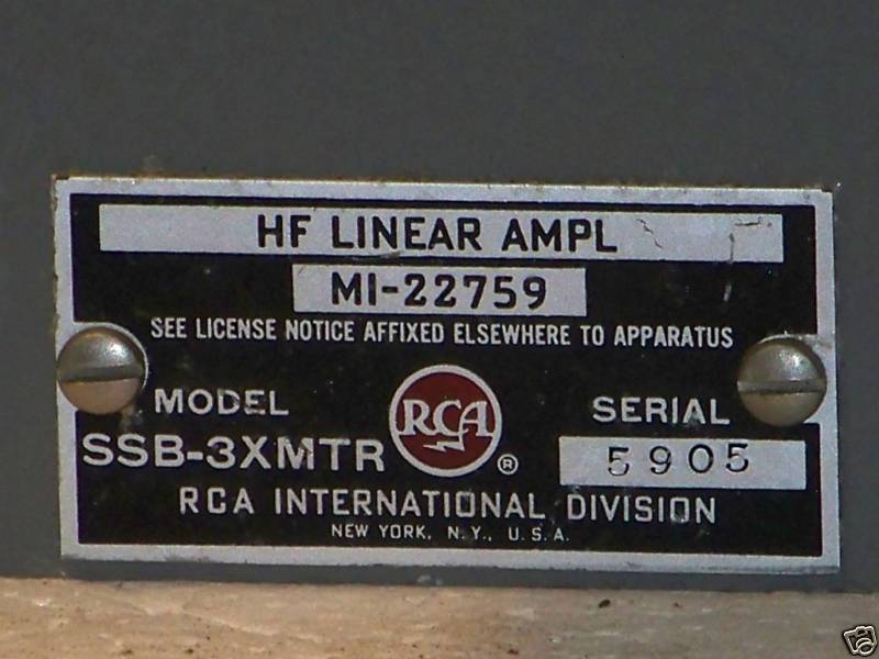
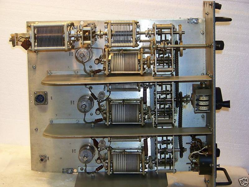
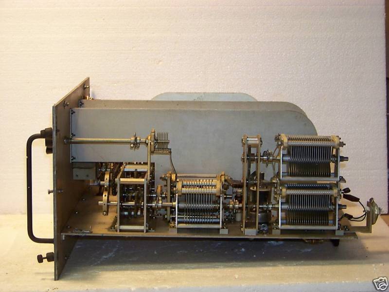
RCA SSB-3XMTR Linear Amplifier - presumably not a Navy item but
interesting anyway - looks like it has 3 gang-tuned amps in parallel, each with
a 6146???
Please e-mail if you have any
info.
 |
 |
 |
 |
 |
 |
Related 1960 RCA SSB mobile transceiver SSB-30LM manual


