- RF and AF Signal Distribution System Type A, B, C - photo, manual download, and info page
- CU-168/FRR Multicoupler - see below for info
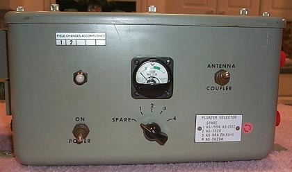
- AN/FRA-3 Remote RF Switch - see below for info

| Shipboard Receiver RF Distribution
|
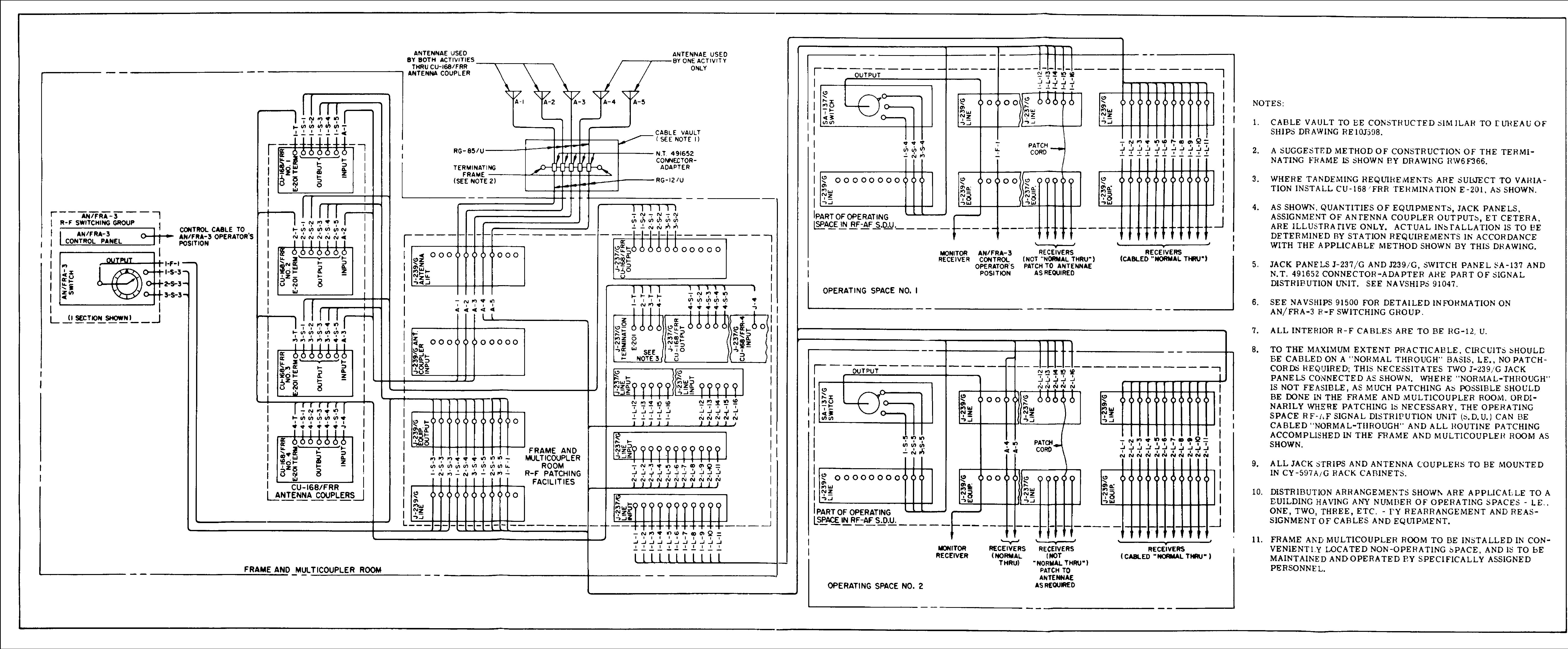
1950's Shore Station Receiver RF Distribution
|
||
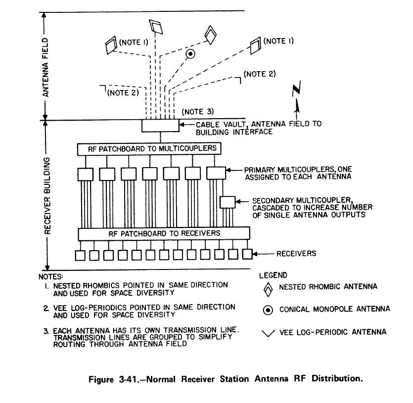
| Normal Receiver Site RF Distribution |
CDAA Receiver Site RF Distribution
|
- | - |
RECEIVING ANTENNA COUPLERS & MULTICOUPLERS
|
|||||
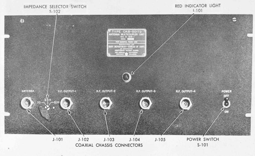
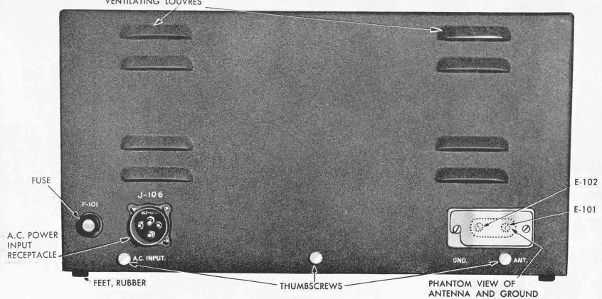
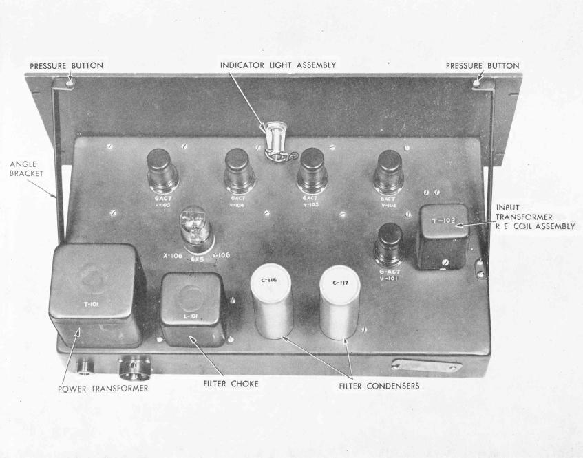
NT-50172 |
|
4-24 mc - 4 outputs
|
Manuf Hoffman |
||
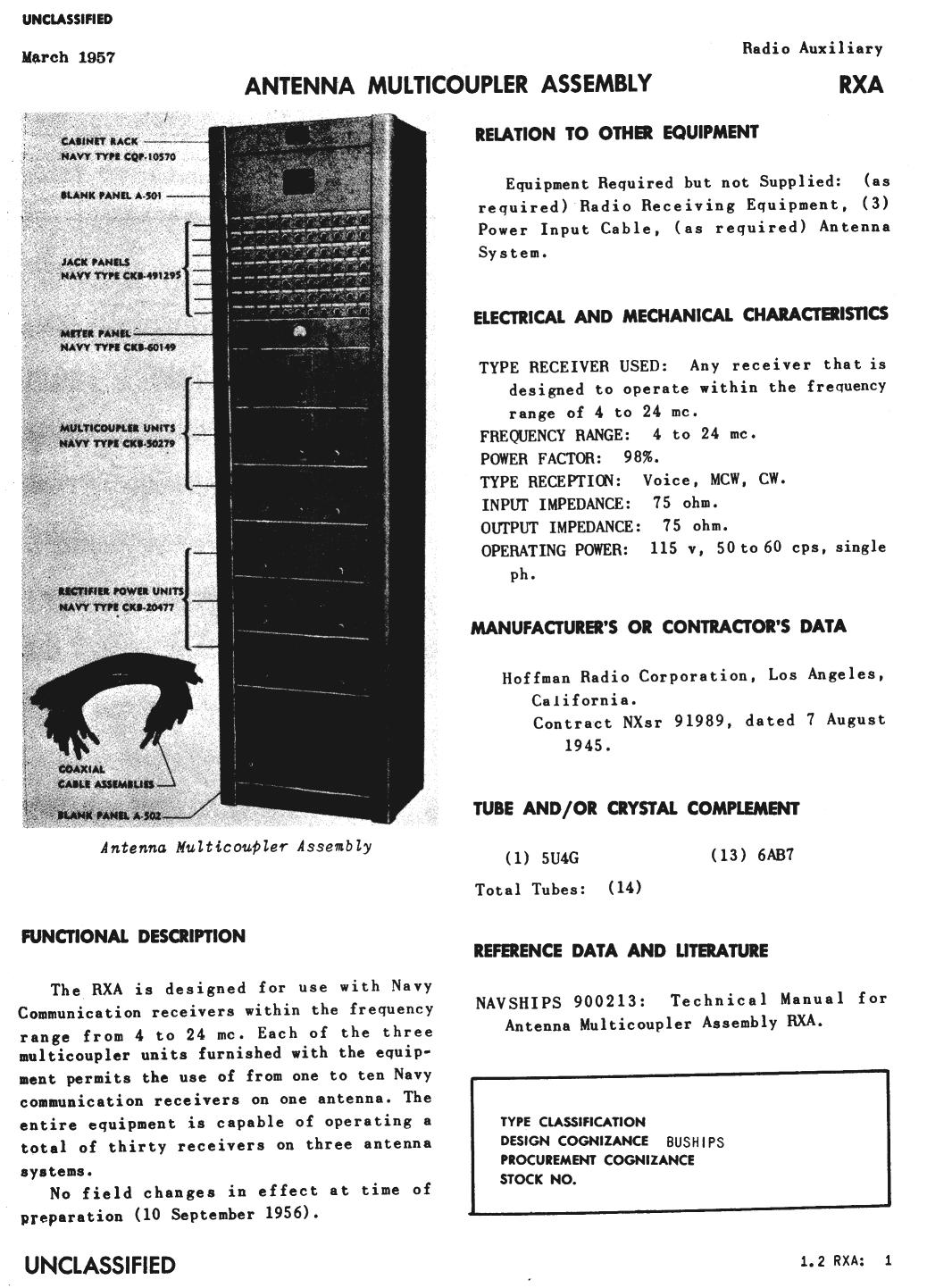
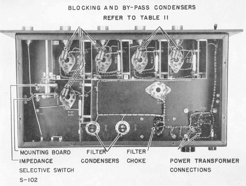
NT-50279RXA |
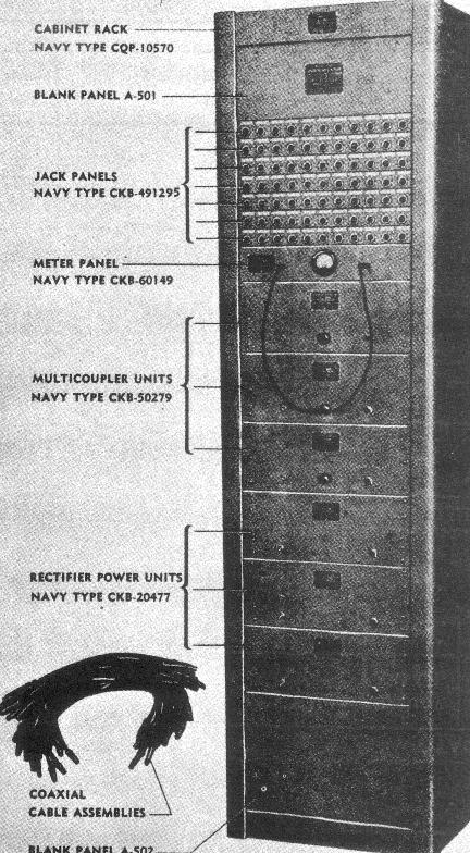 |
4-24mc, 3 antenna inputs, up to 10 receivers on
each Uses NT-50279 multicoupler
|
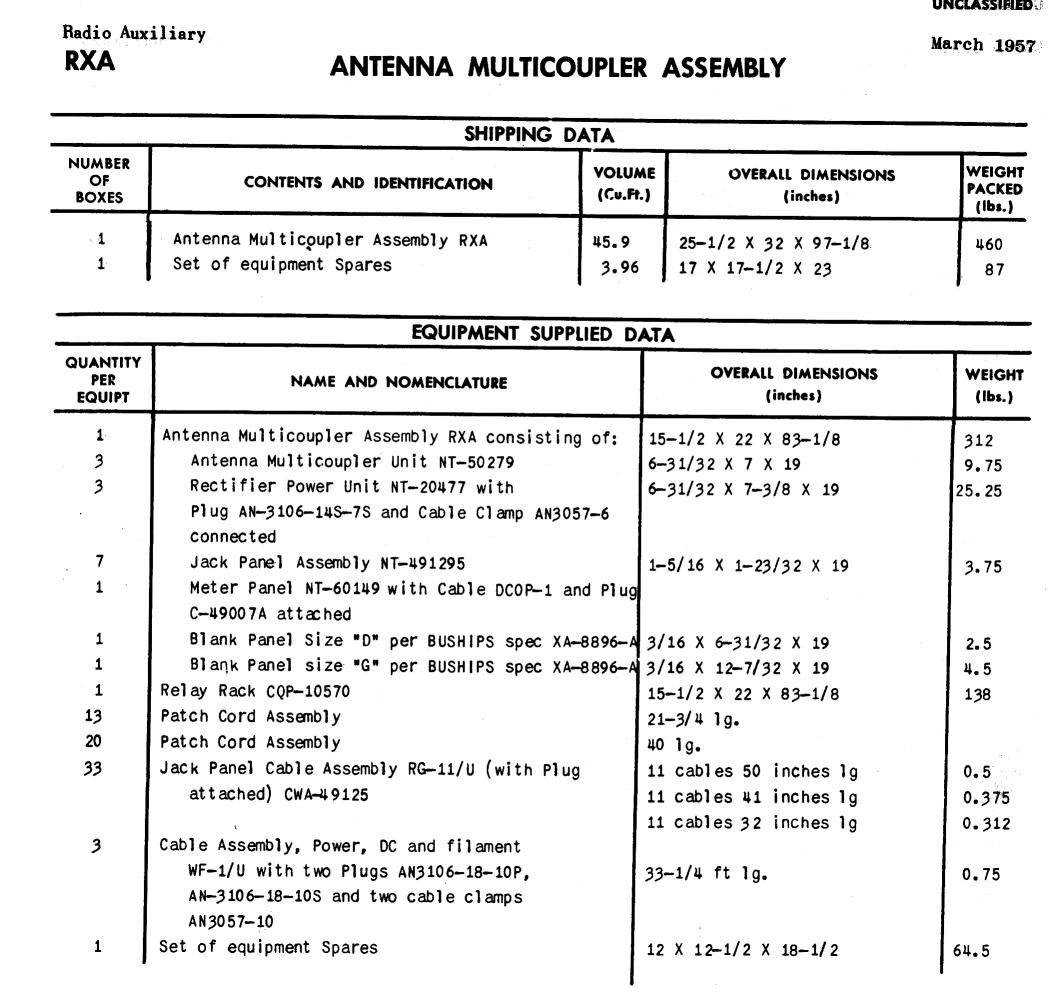
Manuf Hoffman |
||
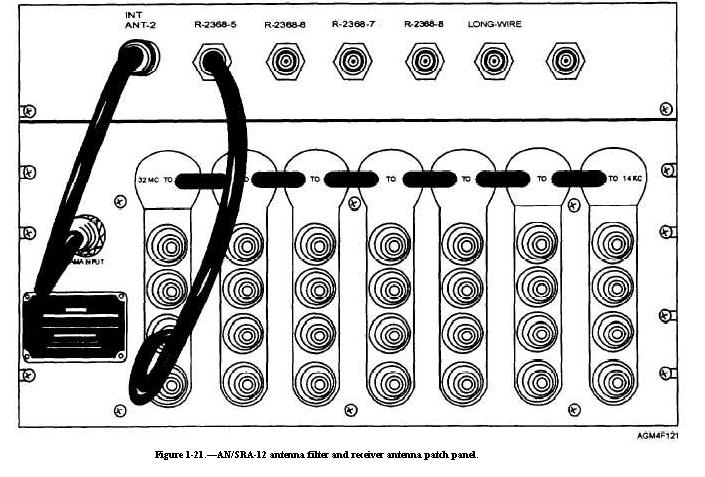
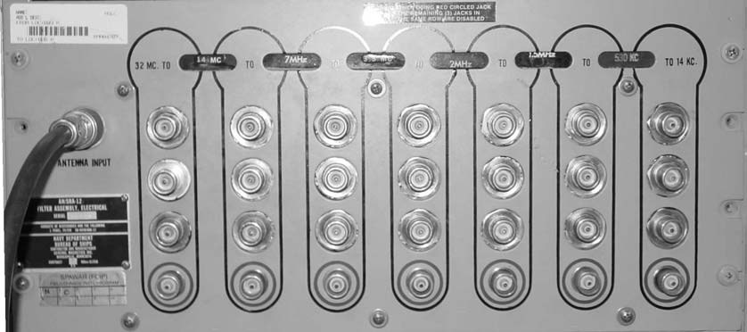
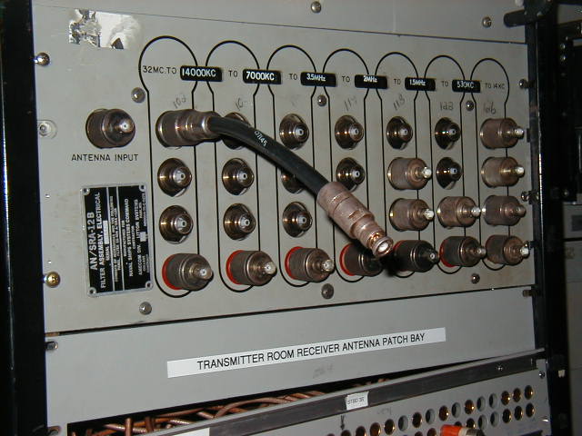
AN/SRA-9
|
|
14kc-32mc - 7 channels Electrical filter assemblies (multicouplers) AN/SRA-9 and AN/SRA-12 are
identical in appearance and function. They are receiving antenna
distribution systems that make possible the multiple operation of a
maximum of 28 radio receivers from a single antenna. Ordinarily it is
preferable, however, to limit the total number of receivers to seven. SRA-9 manual NAVSHIPS 91777 |
|||
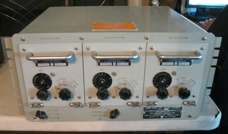
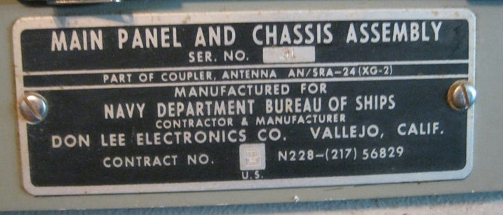
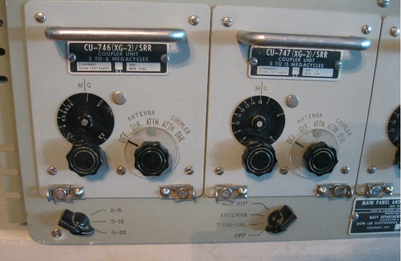
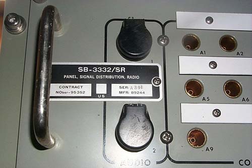
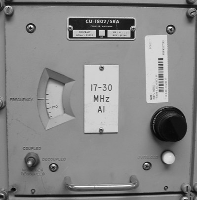
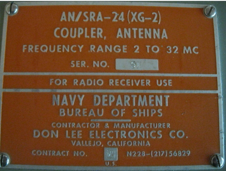
AN/SRA-24(XG-2) |
|
Receiving Antenna Coupler - 3 antenna inputs (plus aux
and calib), one rcvr output Components: |
- please send me e-mail
with any info and photos
|
||
|
|
|
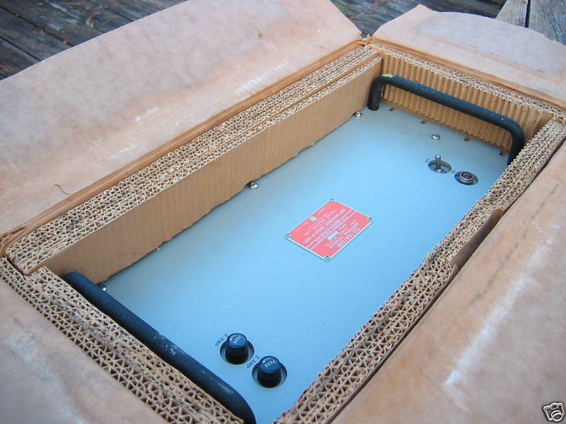
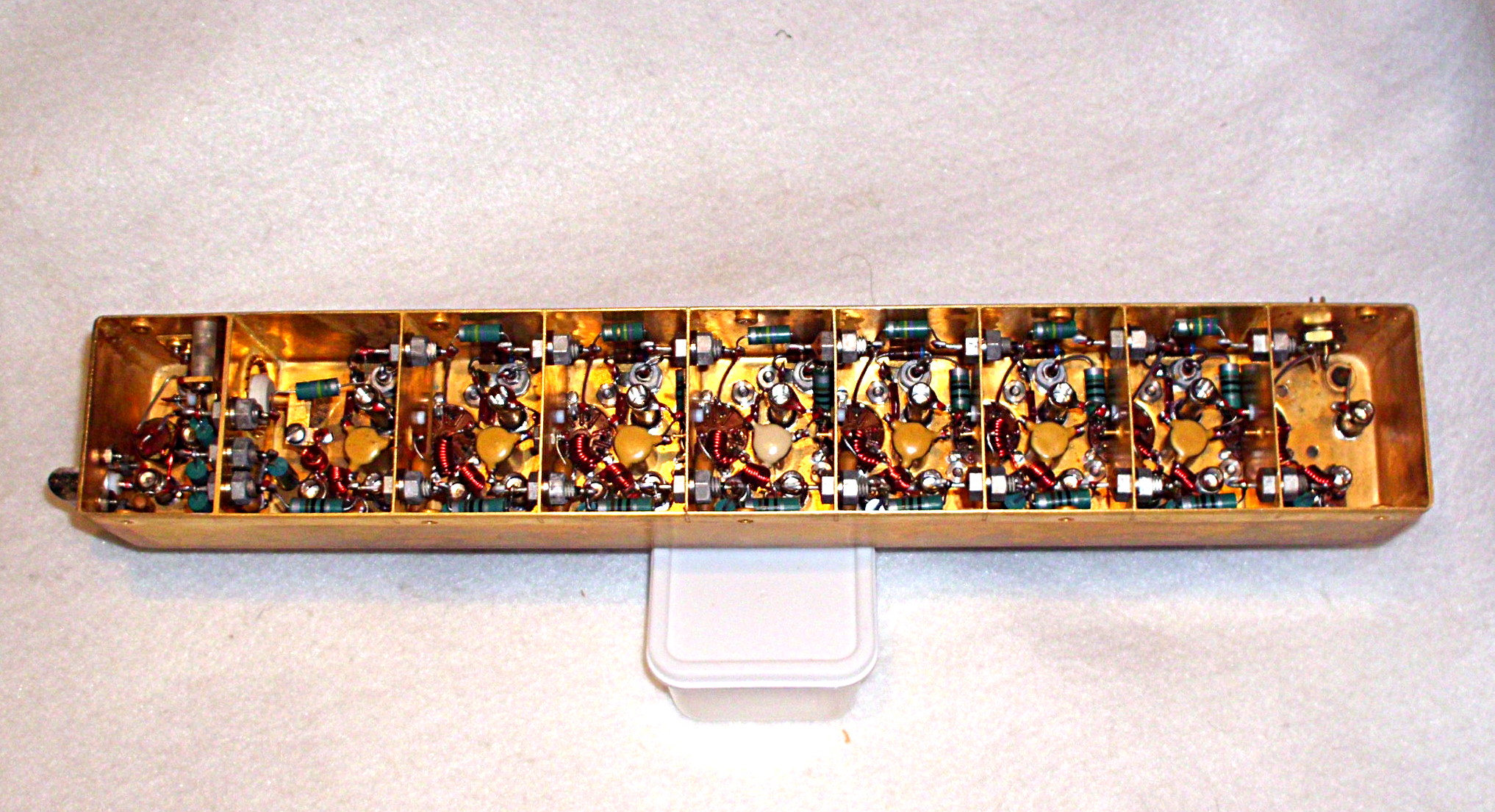
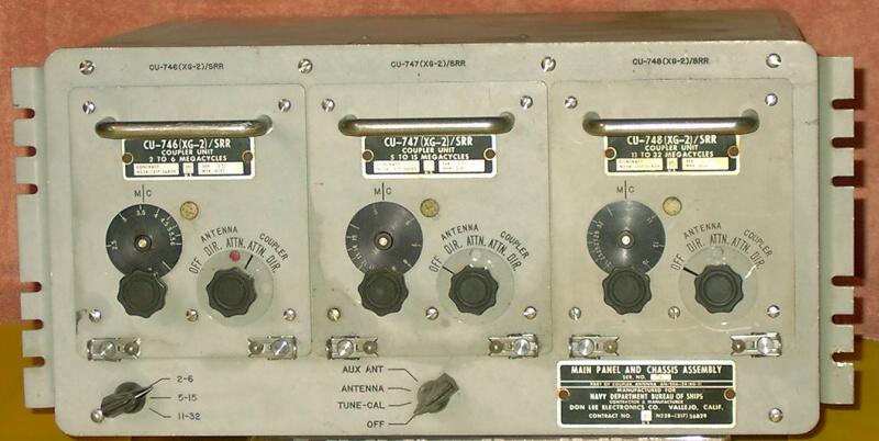
CU-748/SRR (11-32 MC) interior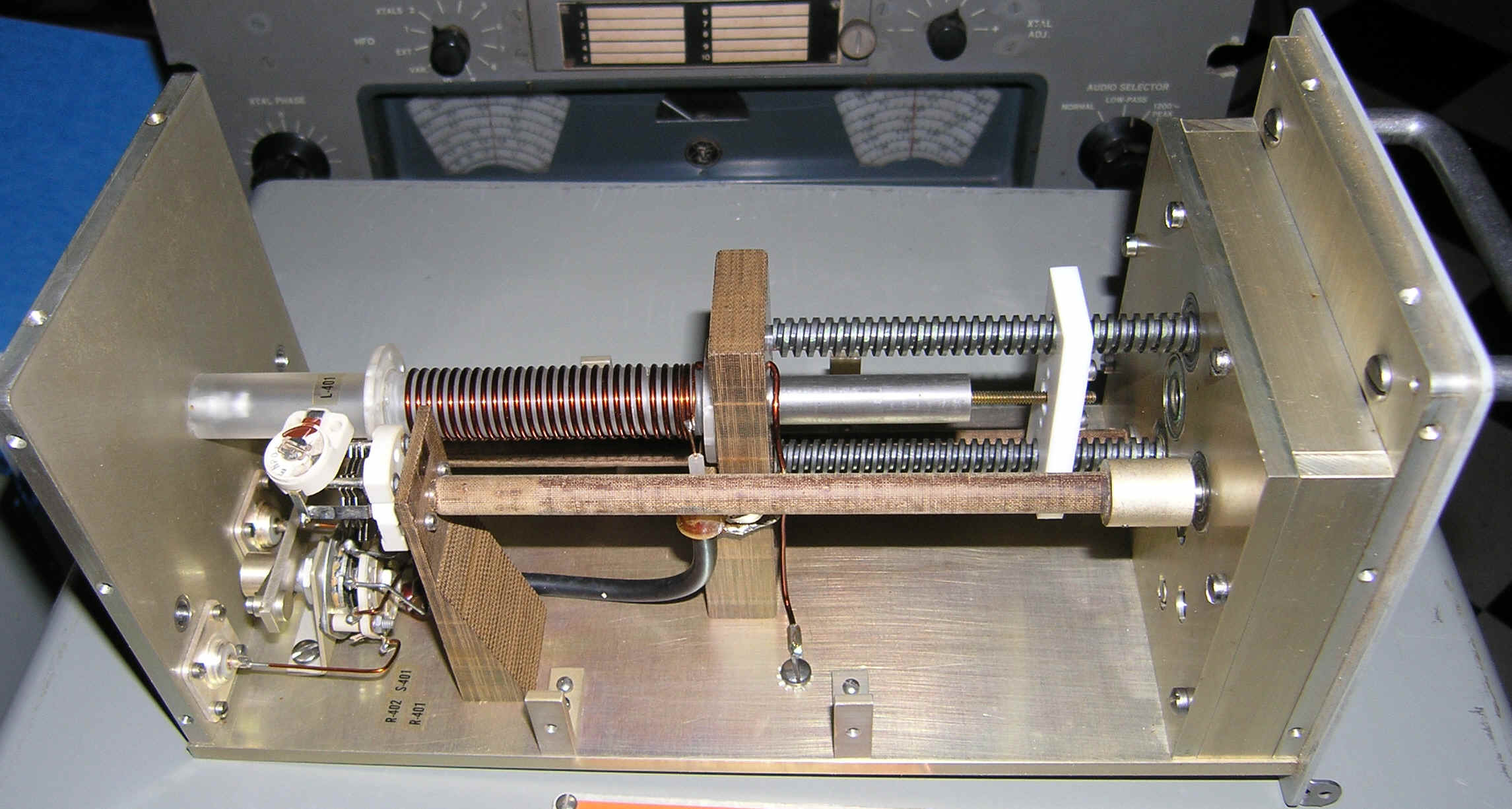
|

|
||
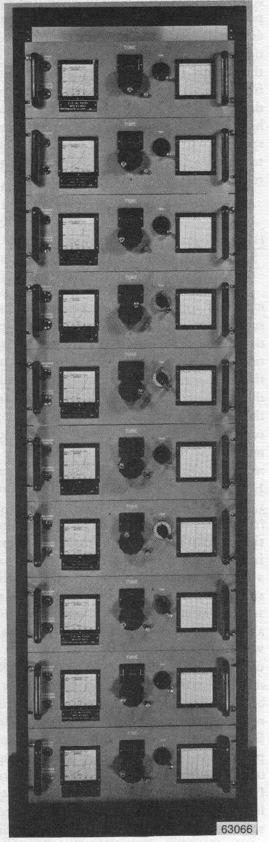
AN/SRA-49 (20 rcvrs 2-30 mc) AN/SRA-49A (20 rcvrs 2-30 mc) AN/SRA-50 (14 rcvrs 2-30 mc) |
|
ANTENNA COUPLER GROUPS -
These groups are designed to connect
up to 20 MF and HF receivers to a single antenna, with a highly selective
degree of frequency isolation. Each of
the six coupler groups consists of 14
to 20 individual antenna couplers and a single
power supply module, all are slide-mounted in a special
electronic equipment rack. An antenna input
distribution line termination (dummy load) is
also supplied. In addition, there are
provisions for patching the outputs from
the various antenna couplers to external
receivers.
Manual NAVSHIPS 0967-303-8610 - Download manual pdf |
|
||
|
|
|

|
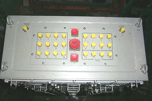 Top View
|
||
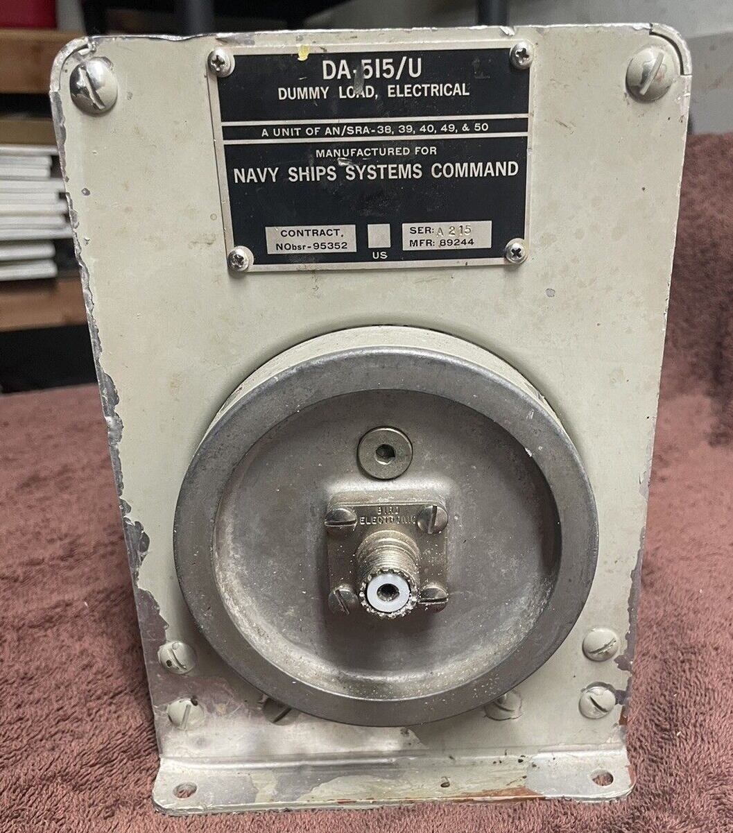
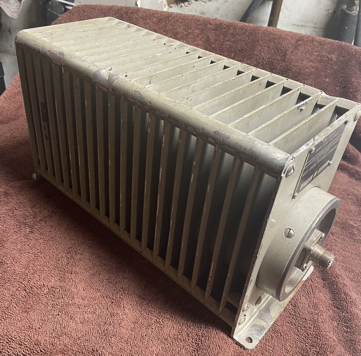
DA-515/UPart of AN/SRA-38, -39, -40, -49, -50
|
|
|
== | ||
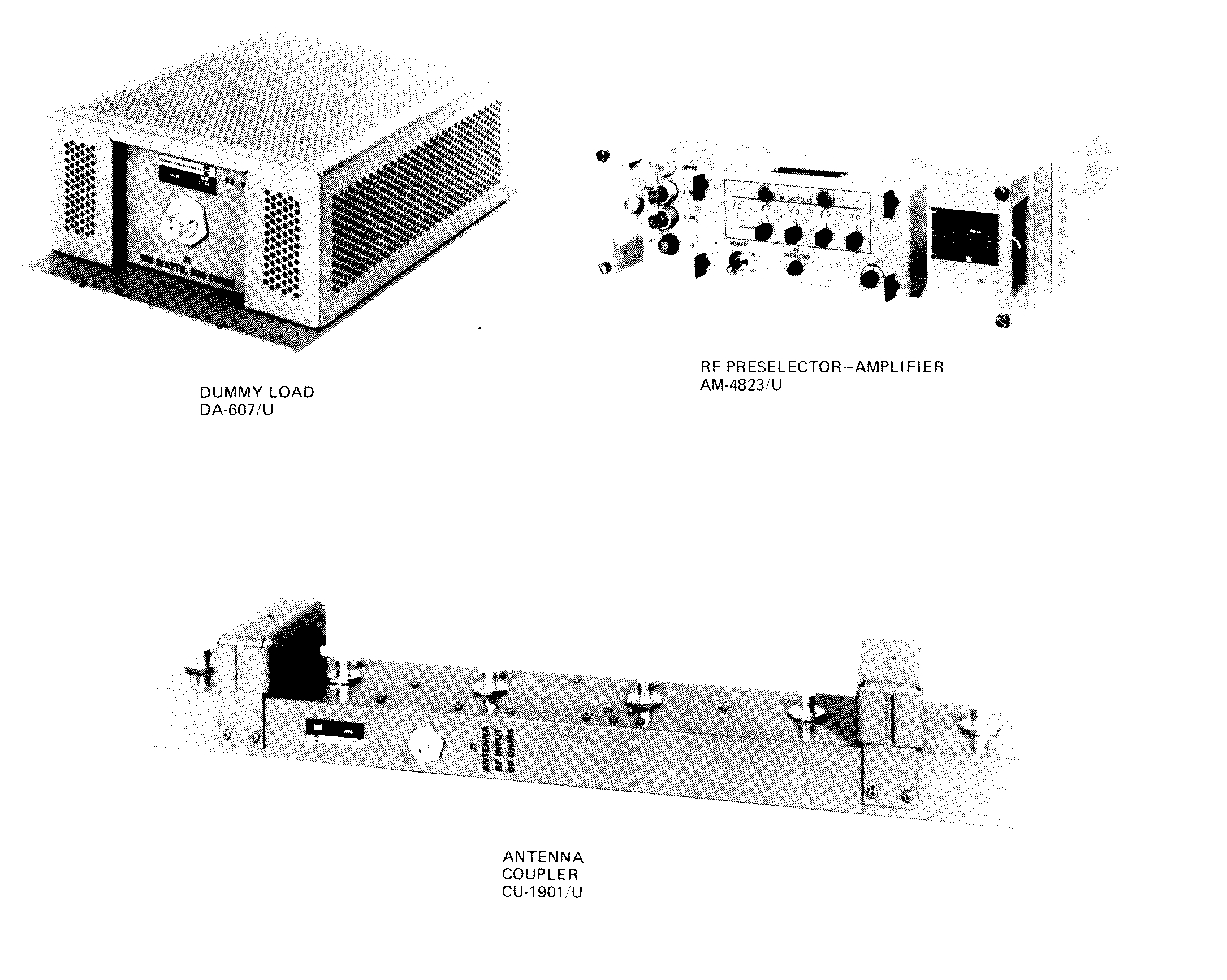
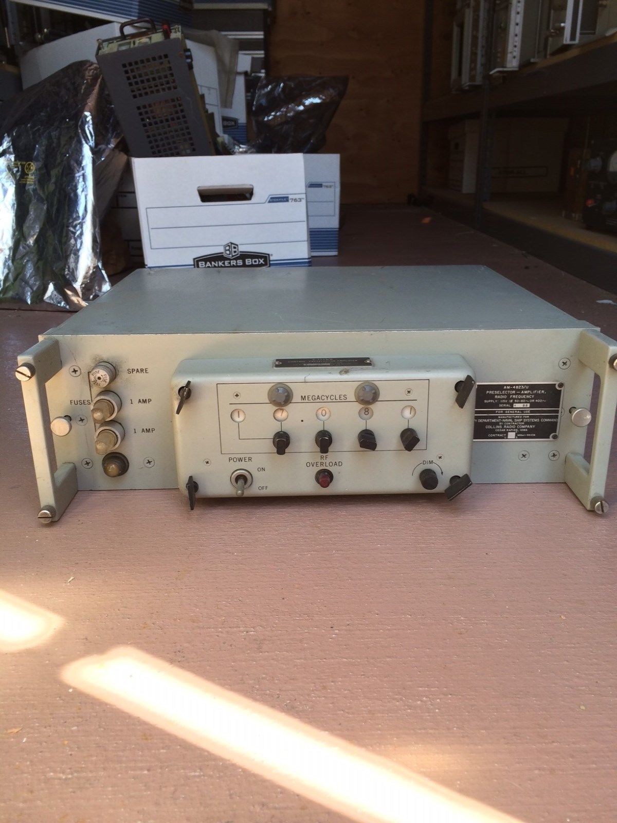
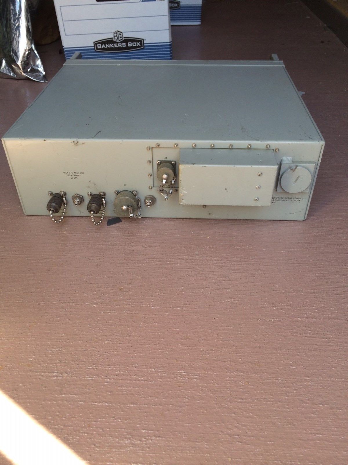
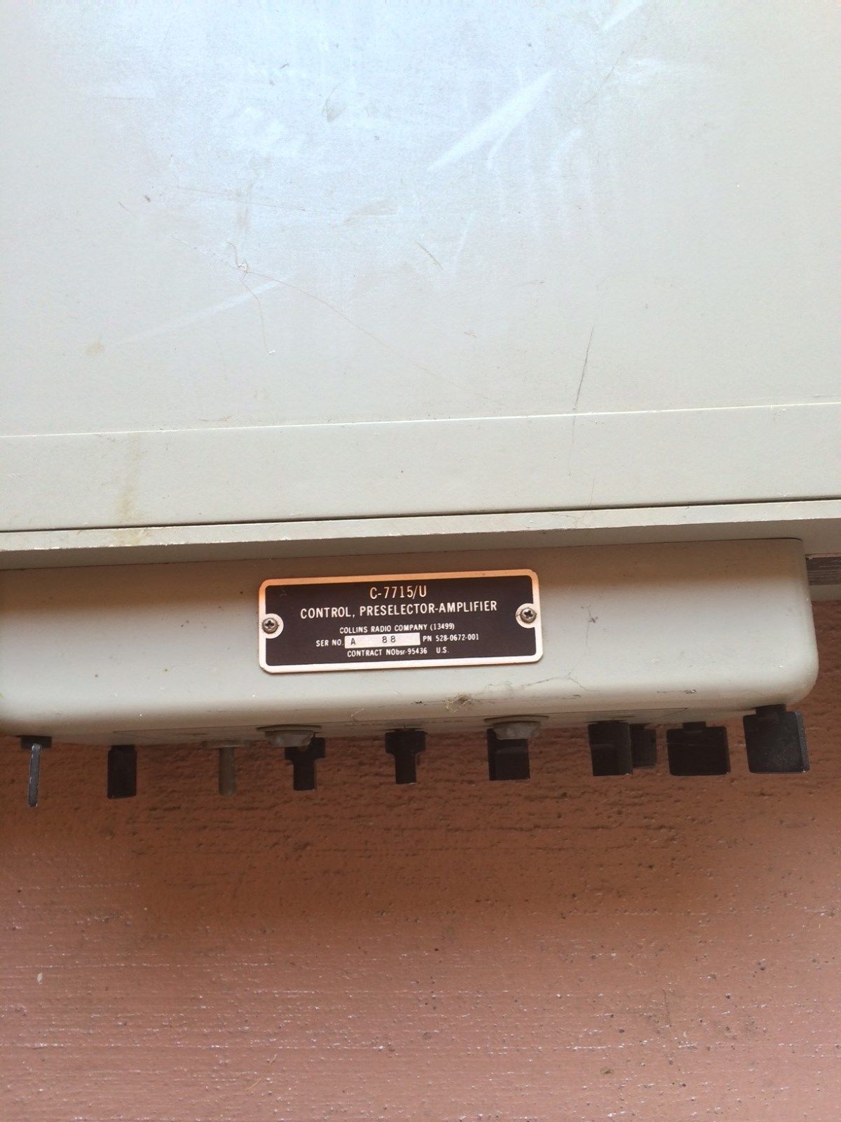
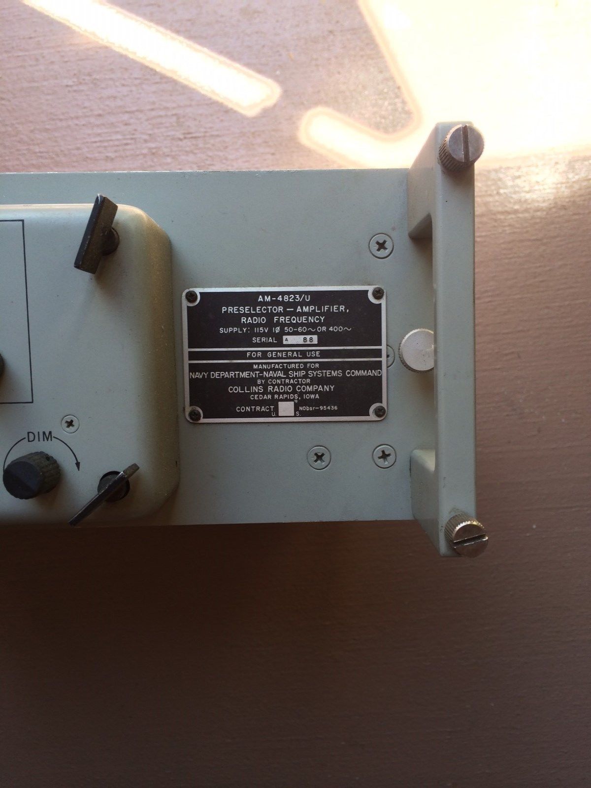
AM-4823/U Preselector/Multicoupler |
|
2-32 mc - allows receiver operation in high RF environments
used with DA-607/U dummy load & CU-1901/U antenna coupler (handles up to six AM-4823/U) need better photos |
Collins
0967-285-3010 |
||
|
|
|
 |
||
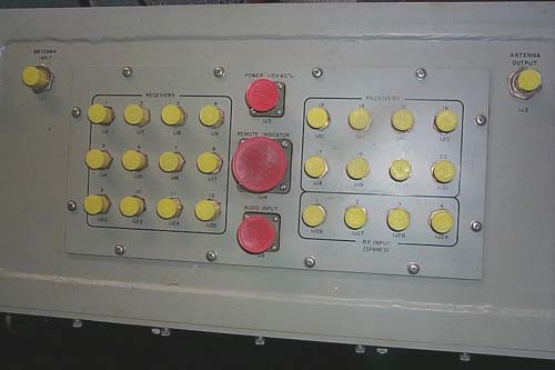
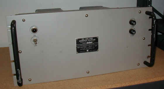
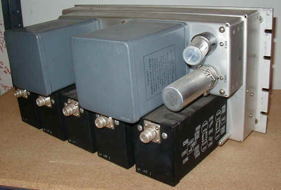
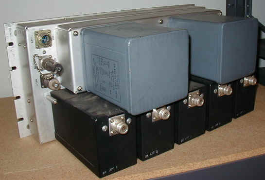
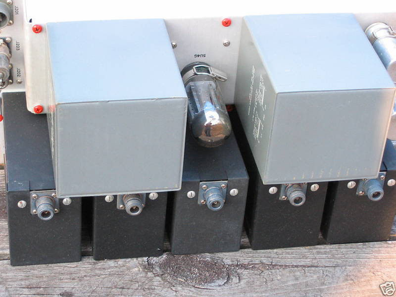
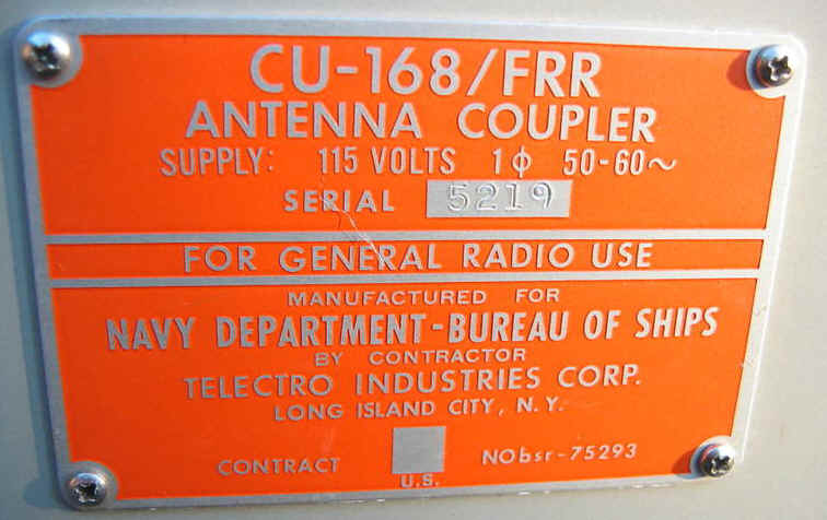
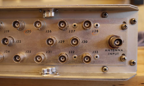
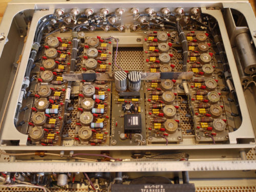
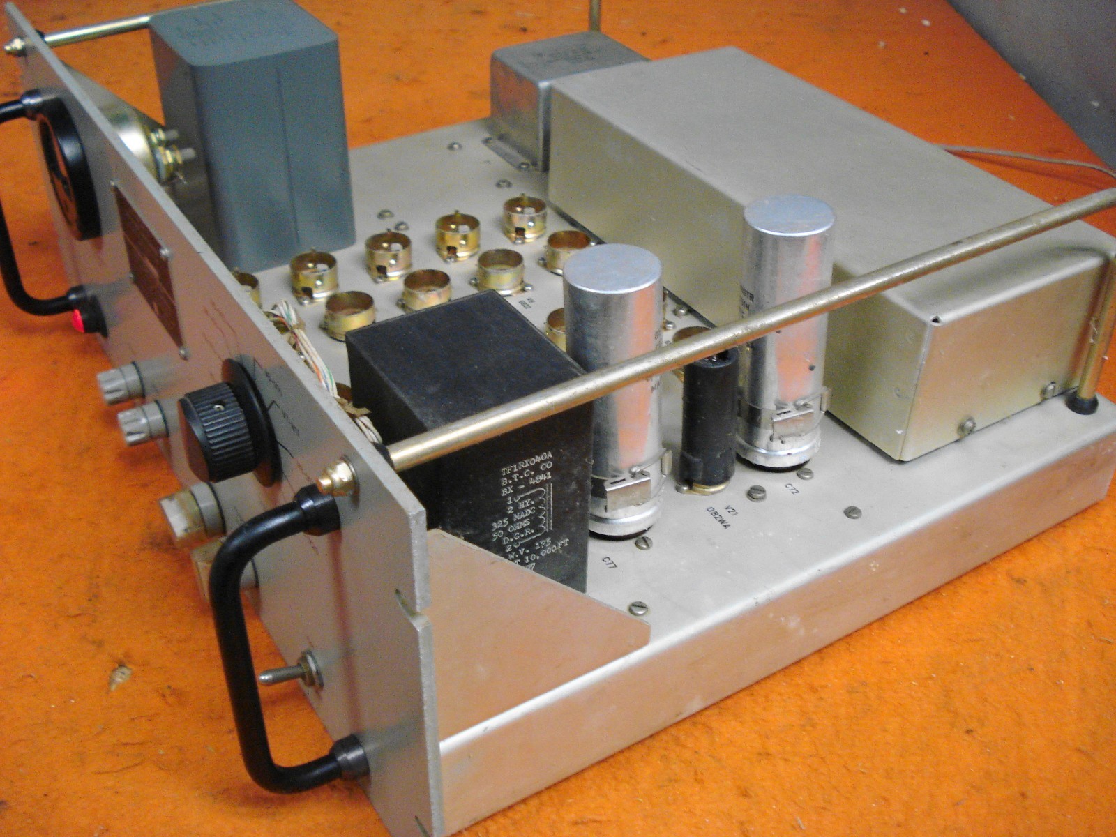
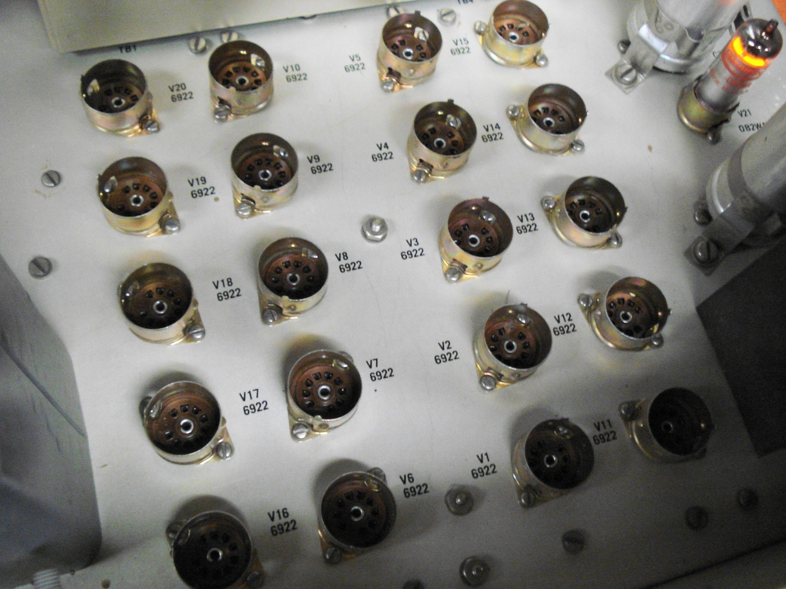
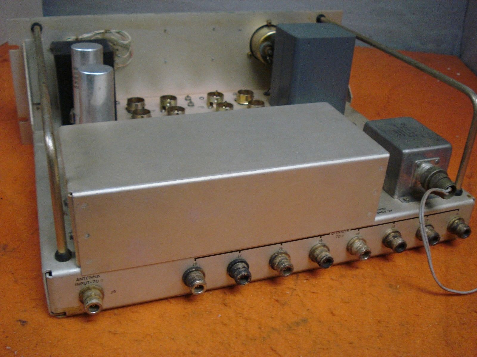
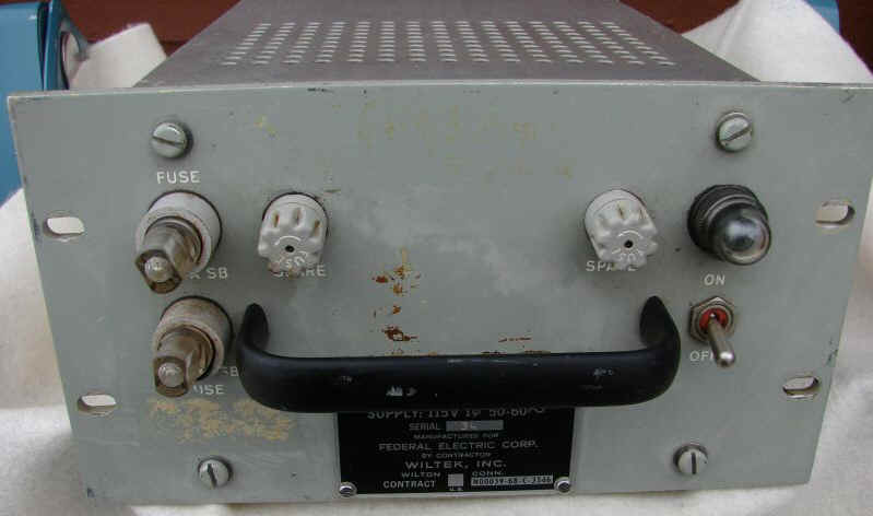
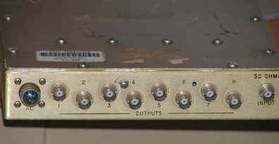
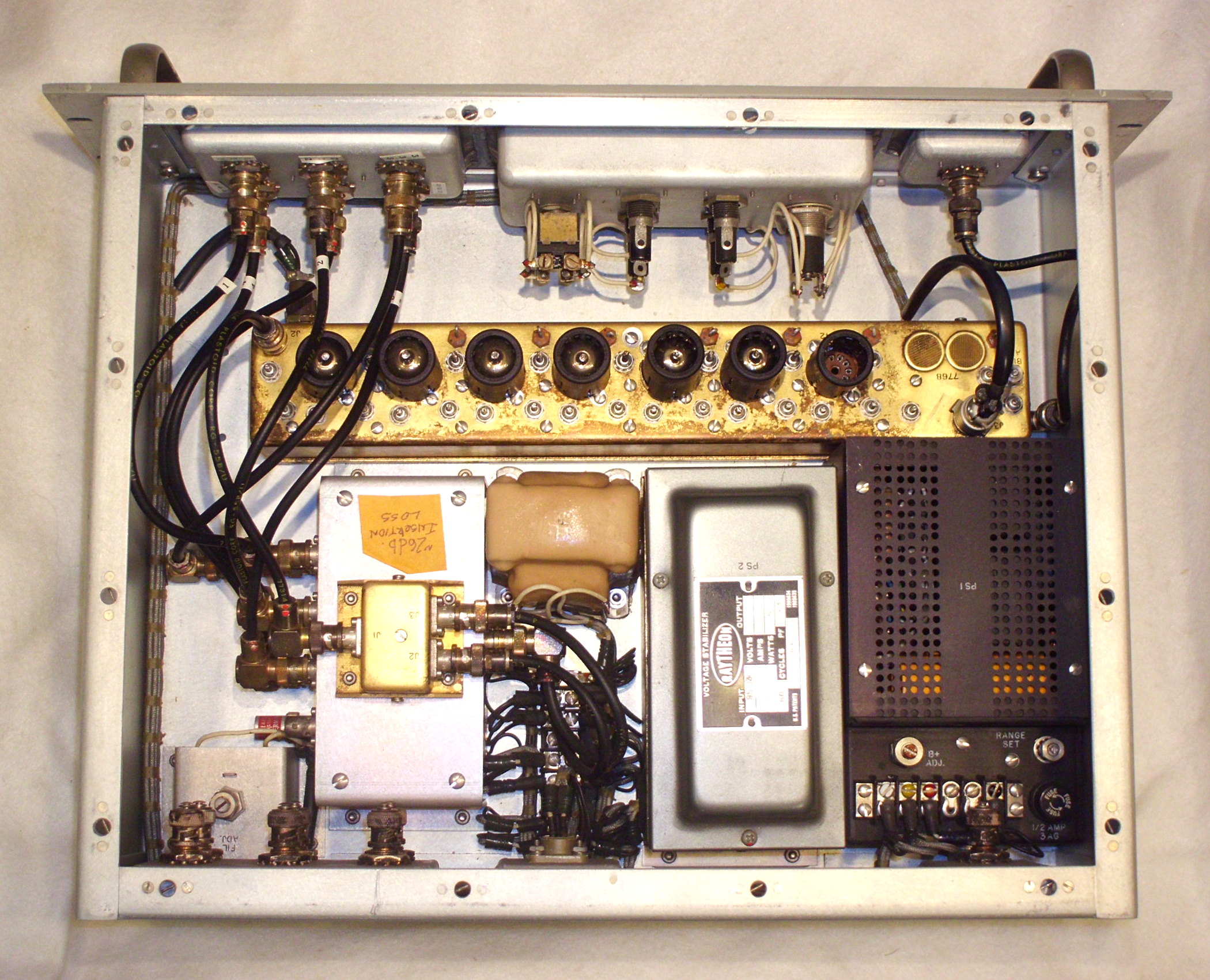
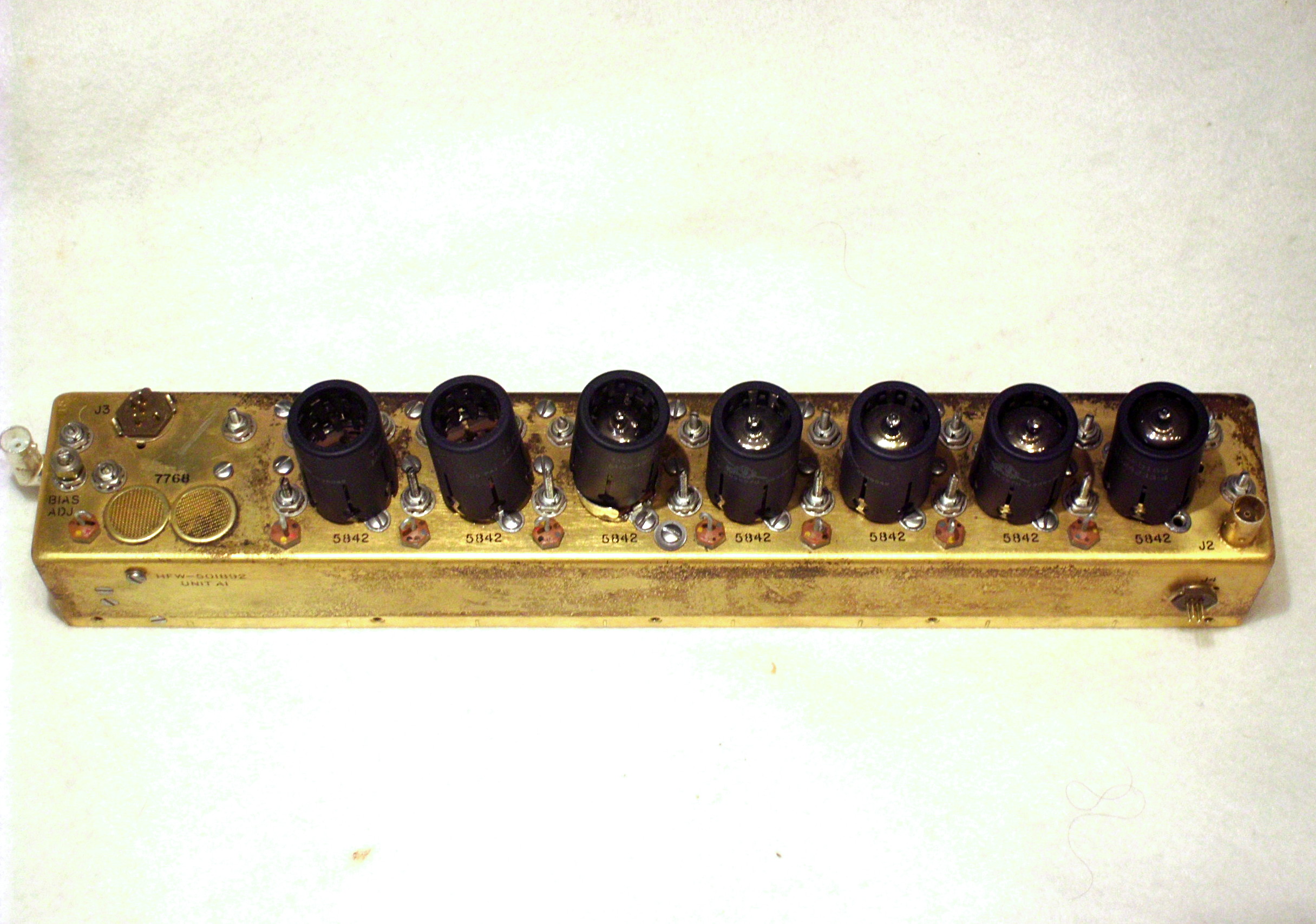
CU-168/FRR |
|
2-32 mc, 5 outputs, tube
technical article
|
Manual NAVSHIPS 91697A
|
||
CU-656/U
|
|
wrong connectors |
2-32 mc, 8 outputs - tube 70 ohm in/out, type C connectors CU-656A/U spec sheetsmanual NAVSHIPS 93804 |
||
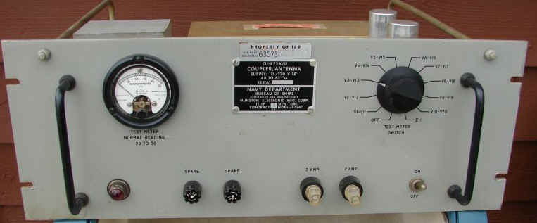
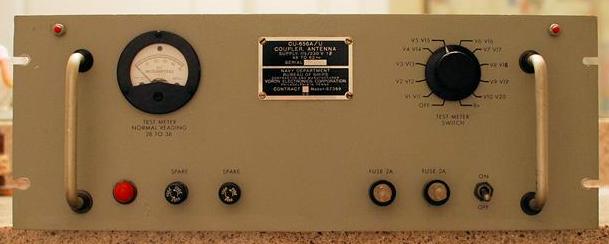
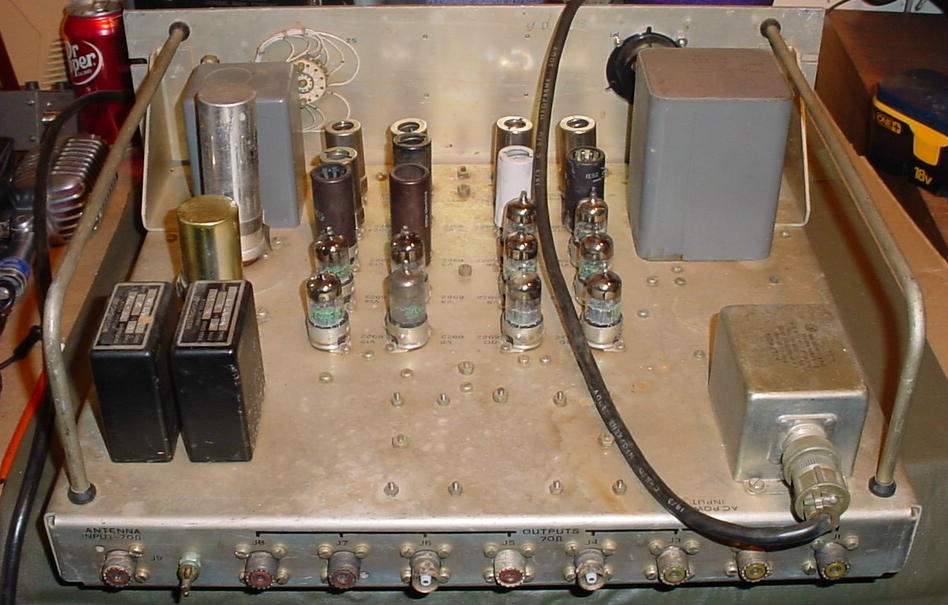
CU-872/U
|
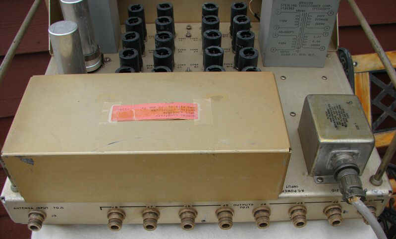 |
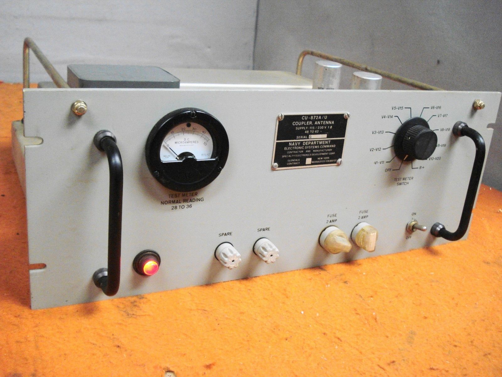 |
2-32mc, 8 outputs - tube 70 ohm in/out, type N connectors Diagram and circuit description NAVSHIPS 93803(A) |
||

|
 |
 |
|
||
CU-873/U |
need photo | need photo | like CU-656/U except type N connectors | ||
CU-874/U |
need photo | need photo | like CU-873/U except 150 ohm balanced input | ||
CU-1099/FRR |
 |
 |
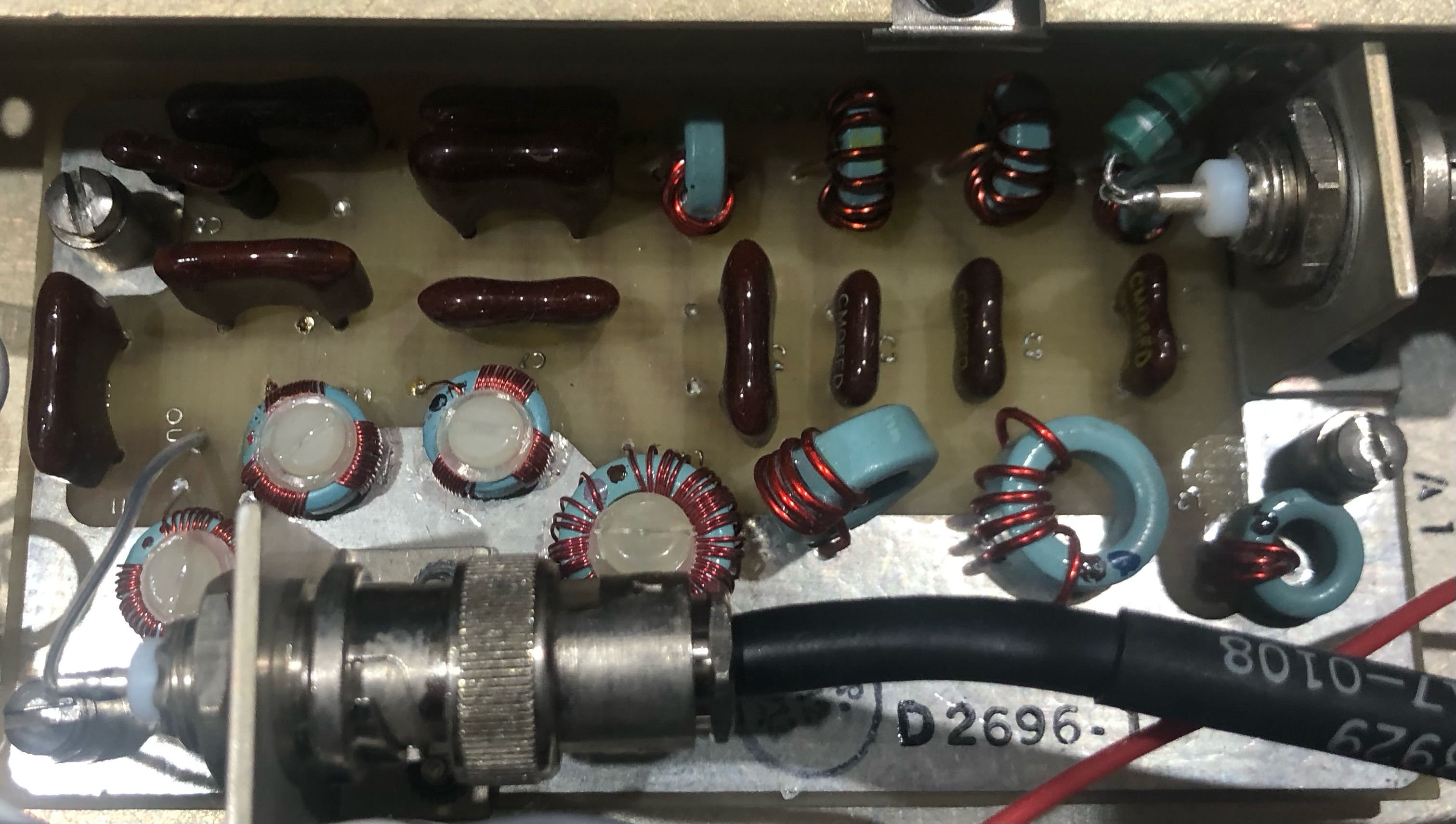
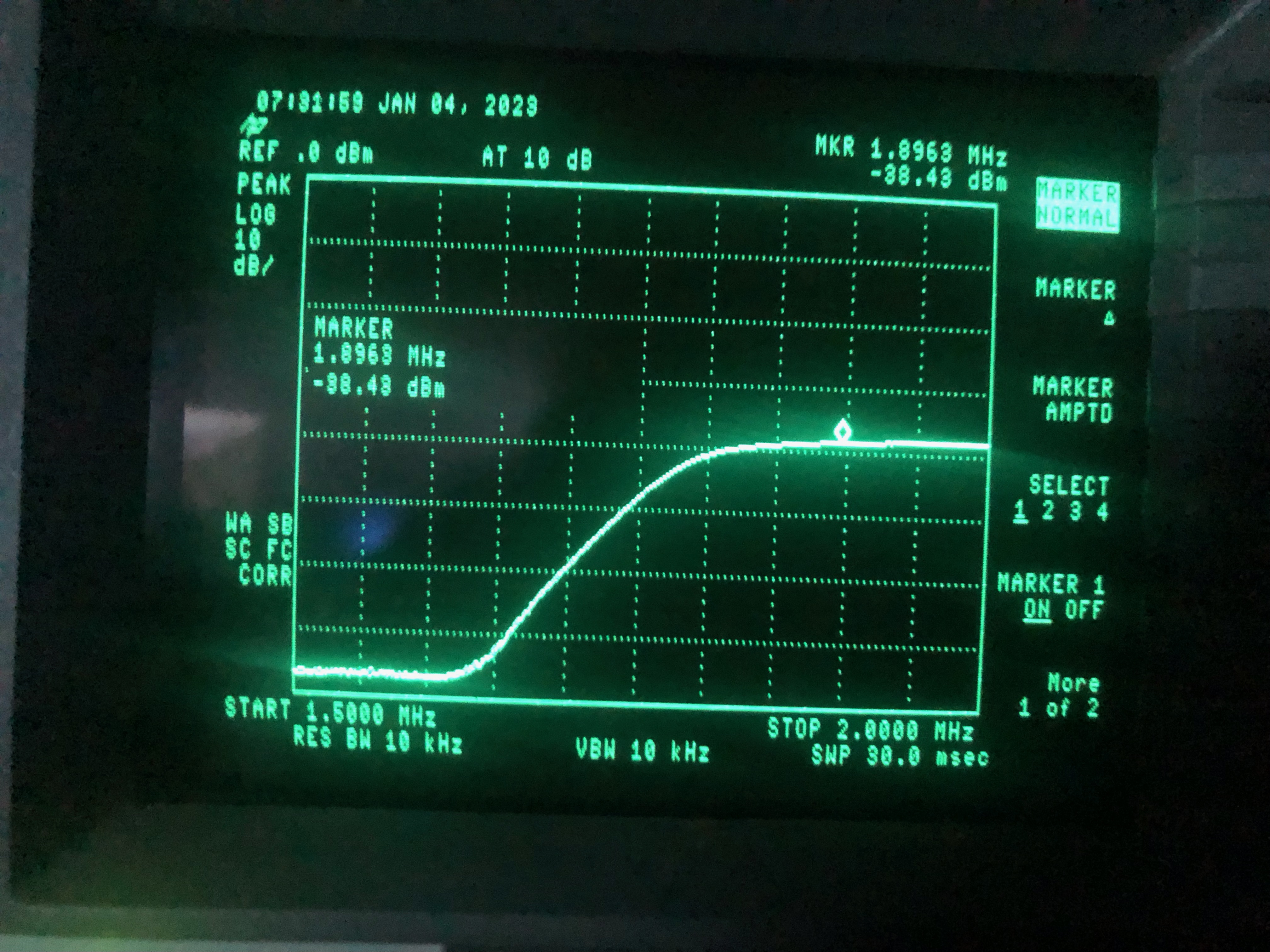
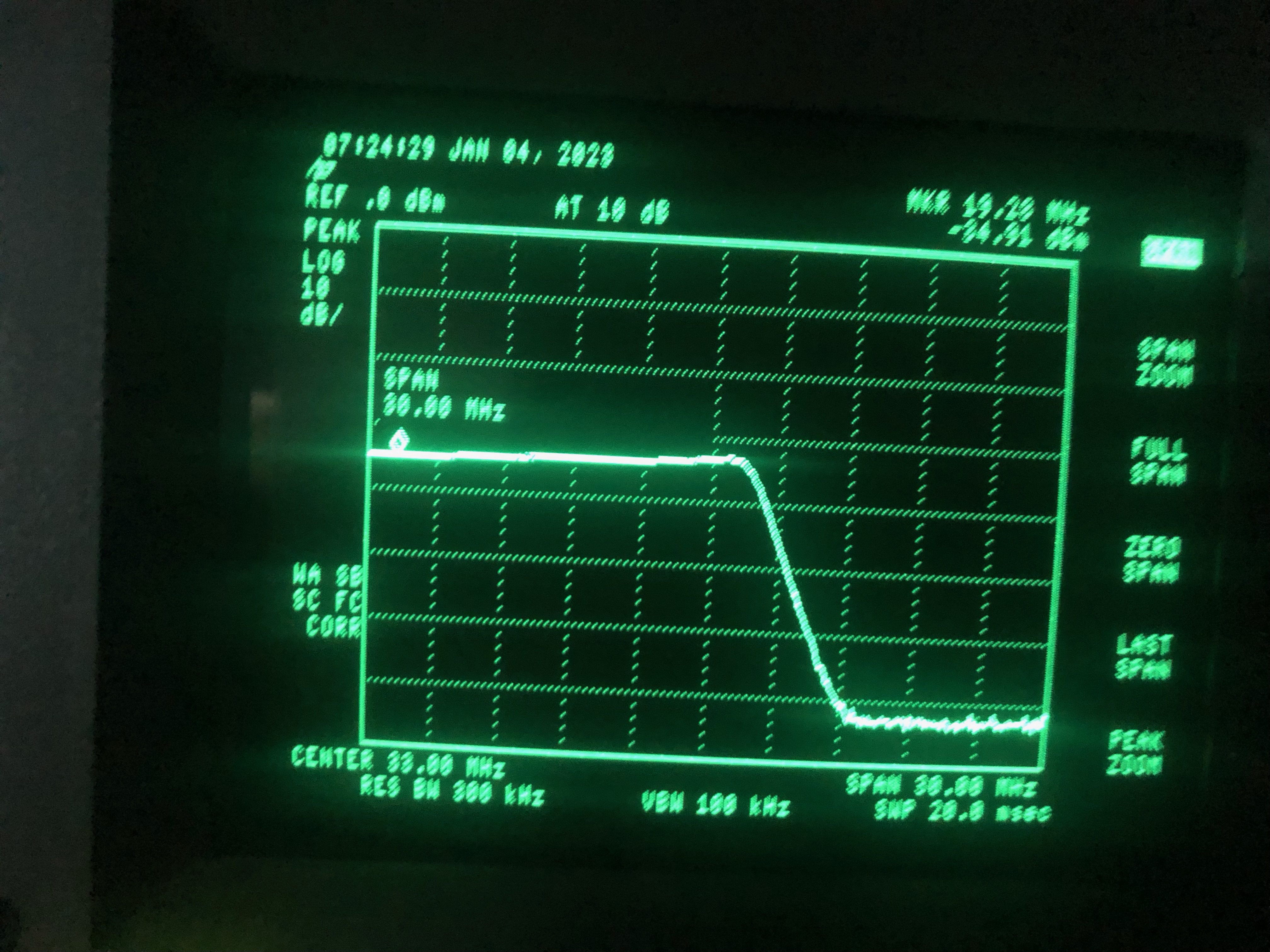
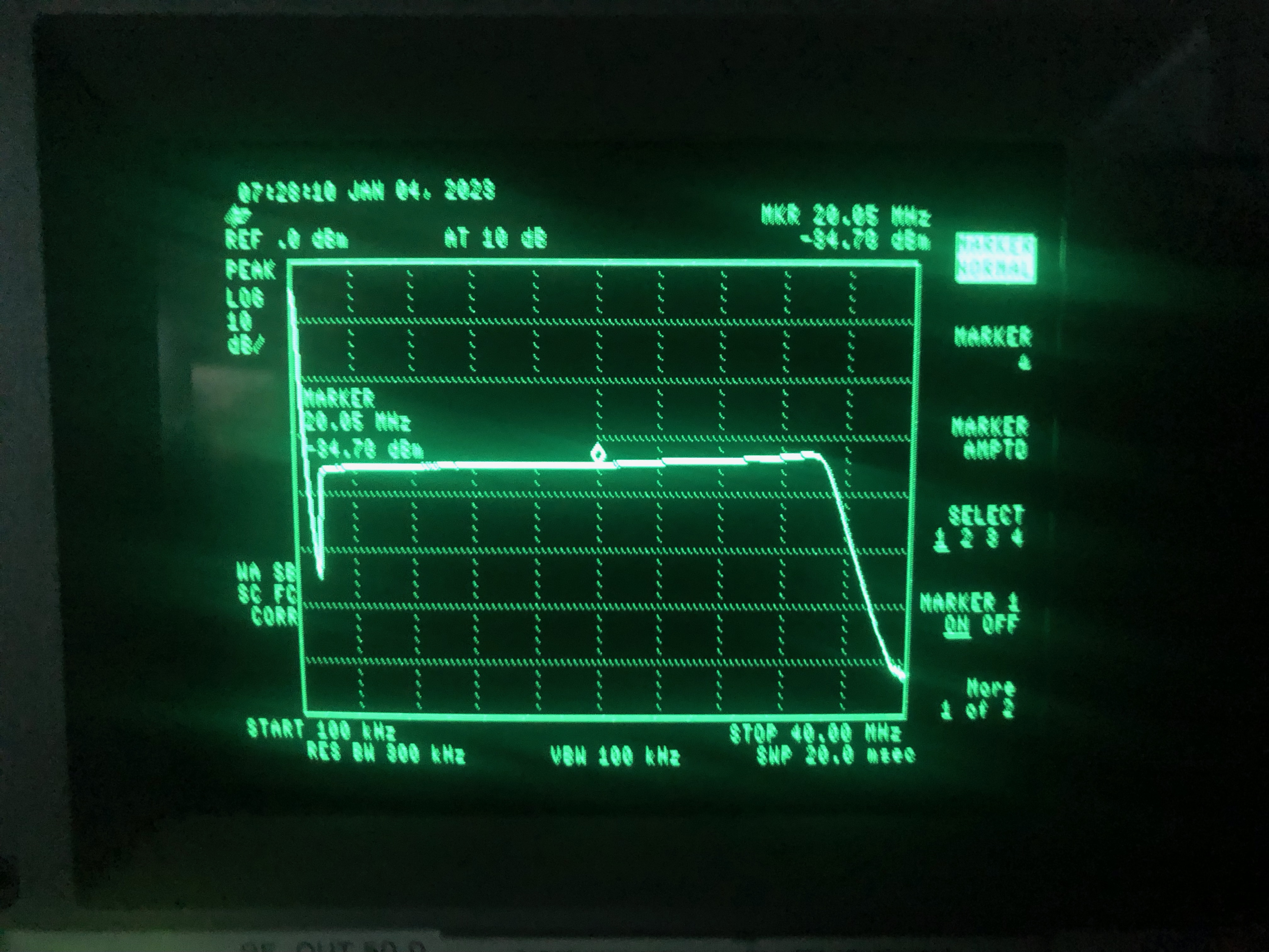
2-32 mc, 8 outputs - transistor 70 ohm in/out, type BNC connectors Diagram and circuit description NAVSHIPS 94933 |
||
CU-1280/FRD-10 |
 |
 |
 |
||
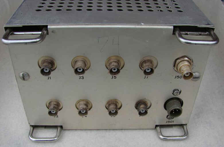
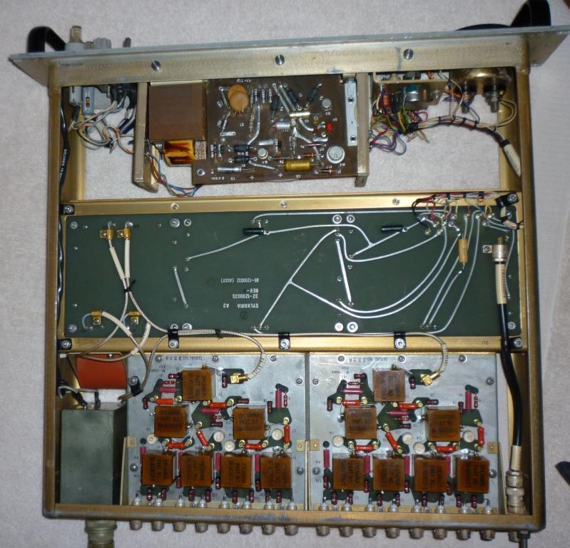
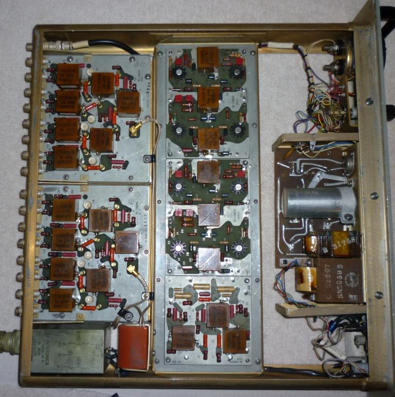
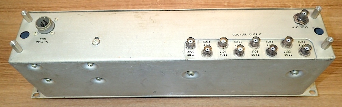
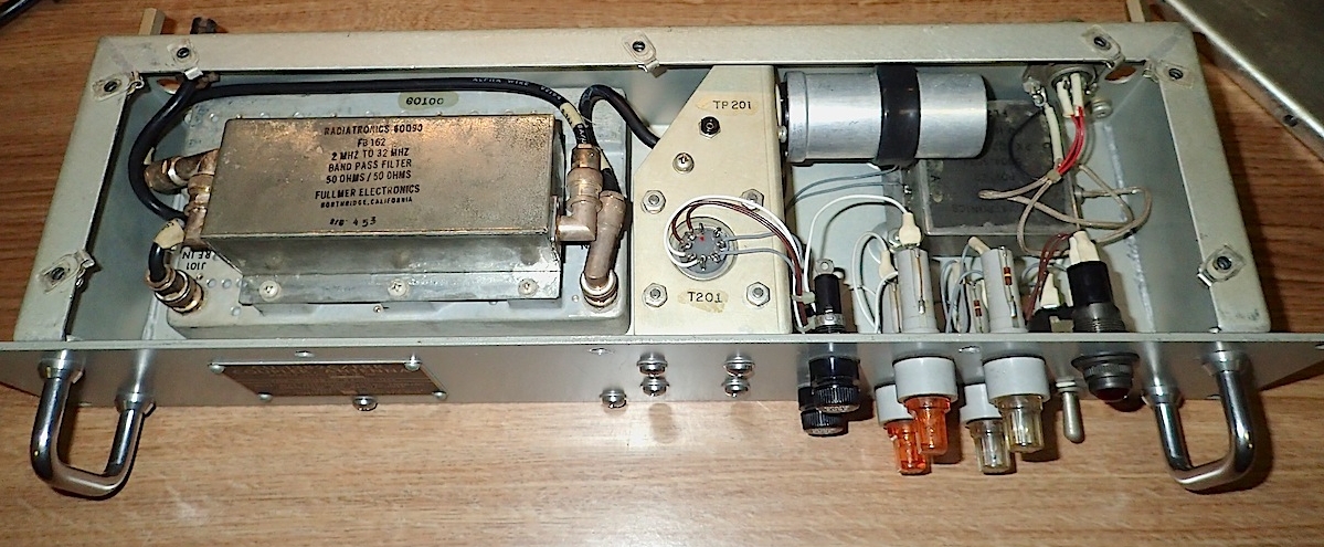
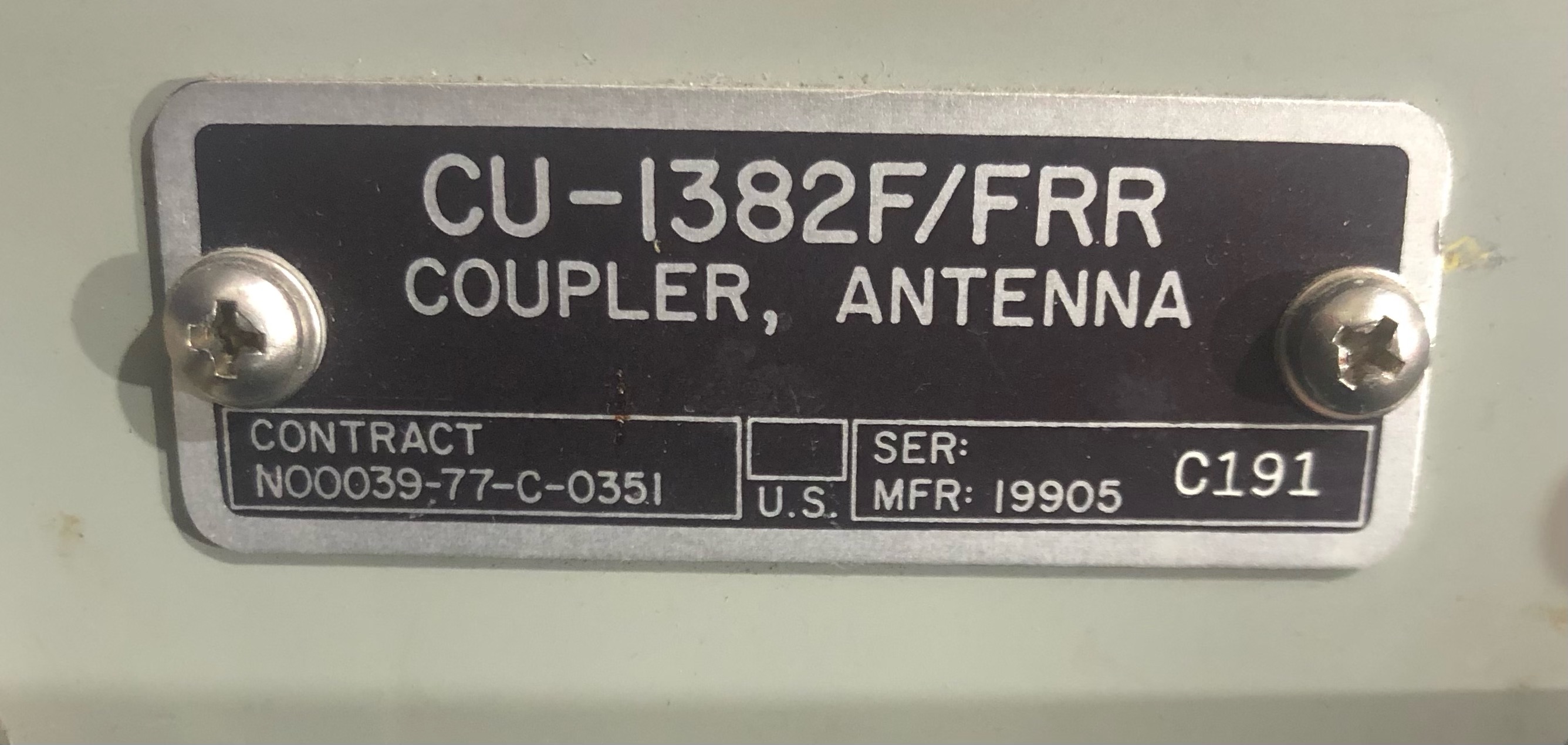
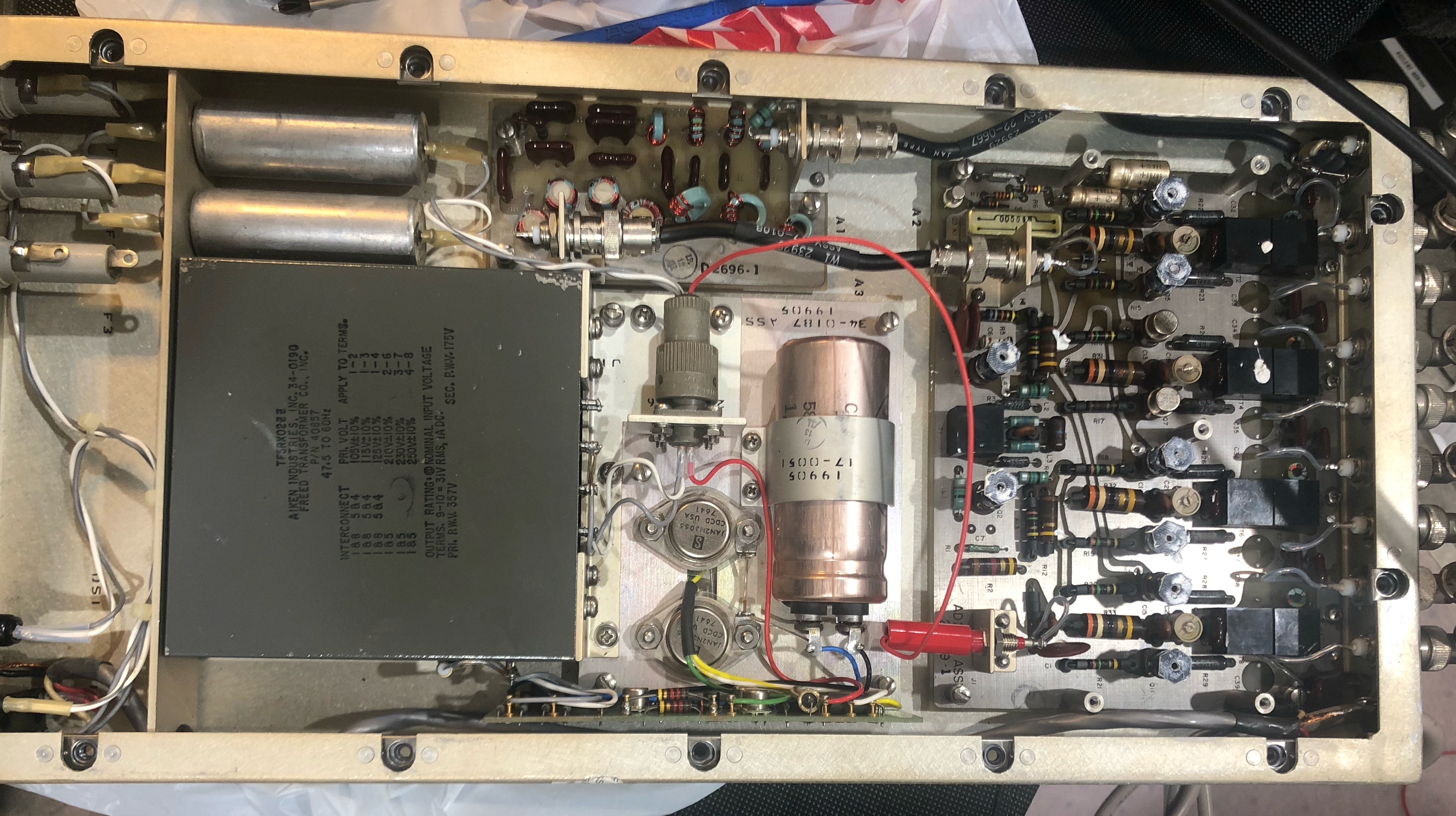
CU-1382/FRR2-32 mc, 8 outputs - transistor thanks to Jim for CU-1382F photos |
CU-1382C/FRR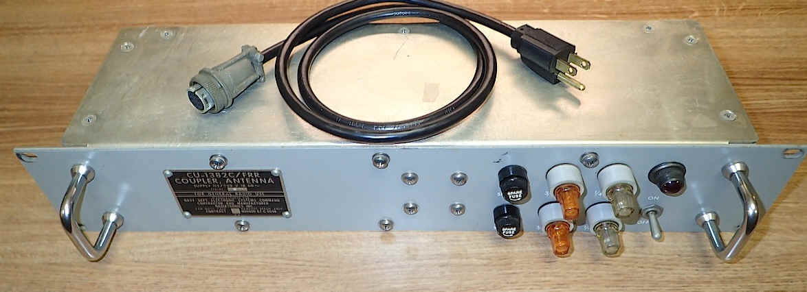 |
 |
 |
||
 |
 |
 |
|||
 |
 |
 |
|||
CU-1382G/FRR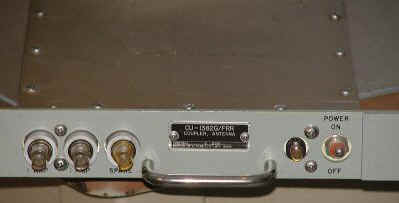 |
 |
== | |||
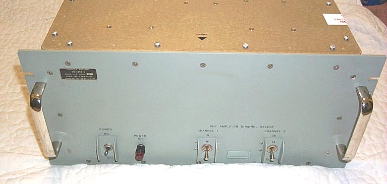
CU-1423/U
|
 |
|
30-300 mc multicoupler 6 outputs Photos thanks to WB2GCR |
||
CU-1563/URR
|
|
10 receivers CU-1563 2-6 mc |
See NRL development page for info | ||
CU-2007/SRR |
 |
Combiner-Multicoupler
8 VLF-LF outputs 10kc-1.85mc 1 HF output 1.85mc-30mc |
More Photos & Info | ||
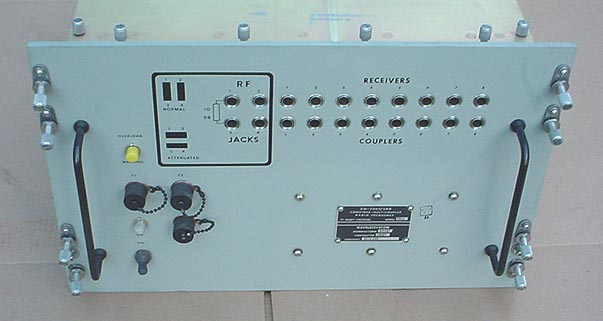
CU-2065/BRR |
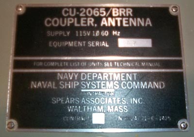 |
VLF-LF & HF outputs
|
 |
||
CU-2268/URR |
 |
VHF and HF outputs | More Photos & Info | ||
CU-5013/SRR |
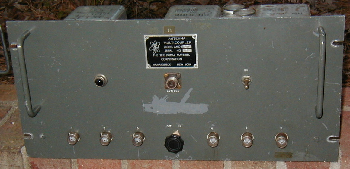 |
 |
2-30 mc - 6 outputs TMC AM6-2/70U 70 ohm in/out, type QC connectors manual - thanks to K4OZY |
||
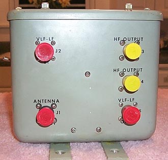
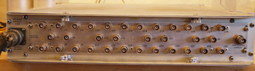
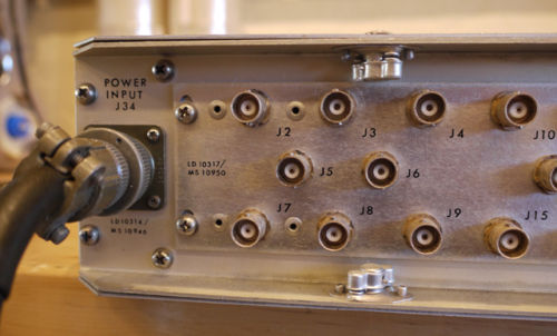
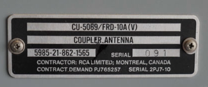
| CU-5069/FRD-10A | 
|
Multicoupler - 32 output HF for CDAA use
|
manuf by TMC for RCA
article with photos - link
|
||