Note 1 - While the AN/FRD-10 was primarily used by NAVSECGRU activities for DF/Intercept, several were also used for general service communications. Two FRD-10's were installed for communications use at Sugar Grove, WV without the DF goniometer. The Imperial Beach, CA and Skaggs Island, CA FRD-10's were shared by SECGRU and COMMSTA (GENSER) activities. Maybe others too - any info is greatly appreciated
Note 2 - The CDAA is also known as a Wullenweber antenna. The basic principle is that signals from a circular array of antenna elements can be combined with proper phasing to create a high-gain directional antenna which is electrically steerable. 1947 NRL report outlining principles of operation.
The FRD-10 had two sets of elements, 120 high band and 40 low band. The AN/FLR-9 was a somewhat different design used by the USAF. - AN/FLR-9 documentary video
Note 3 - The AN/FLR-7 Countermeasures Receiving Set and
AN/FRA-44 Direction Finder Set
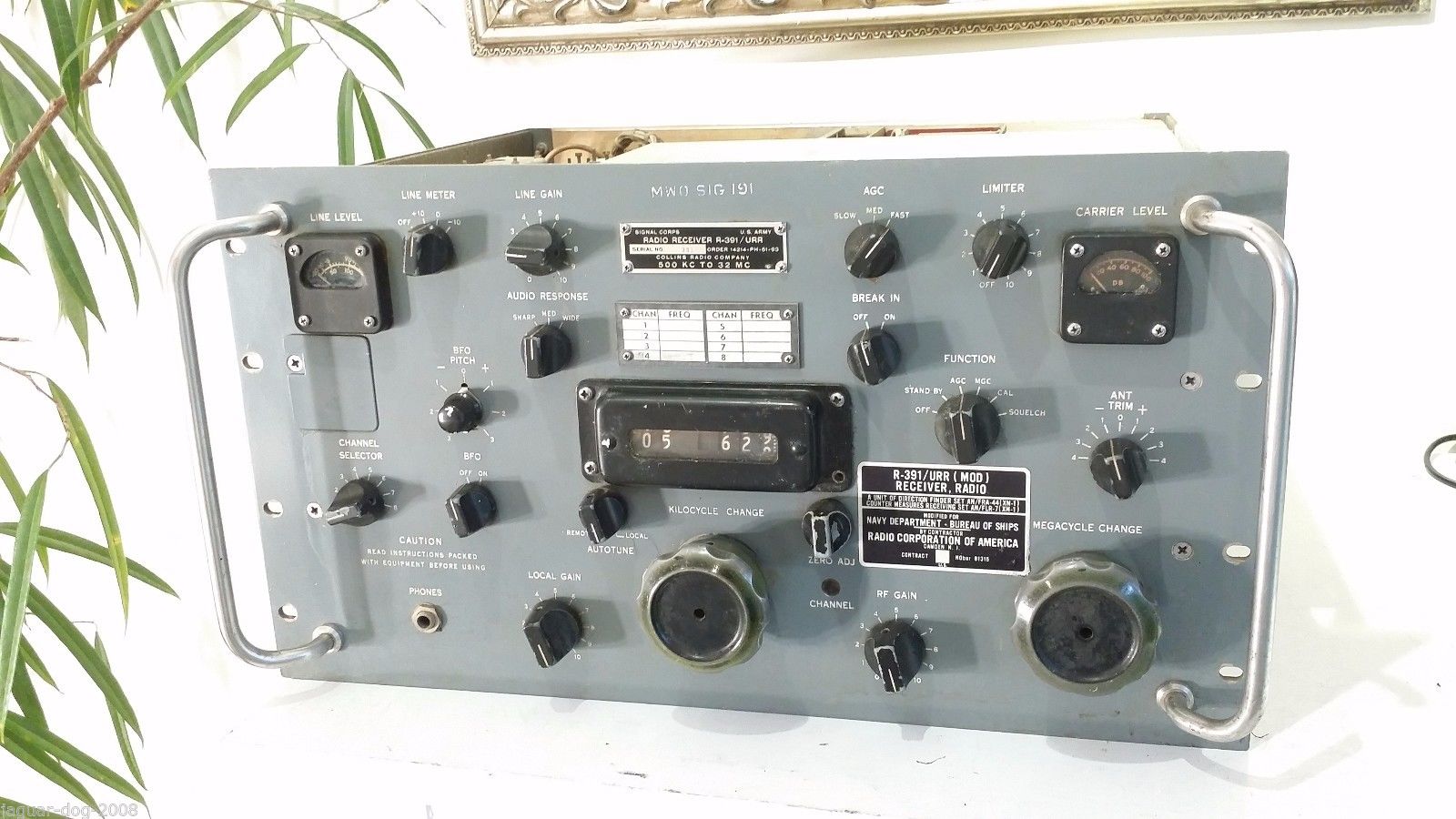
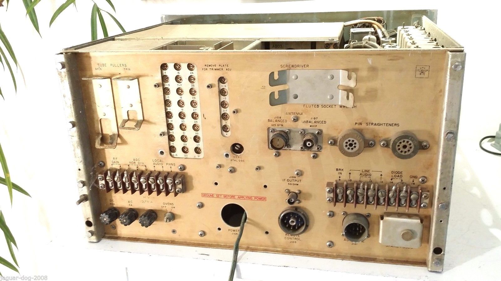
(Modified R-391/URR receivers, later modified R-390) were used with the CDAA.
The AN/FLR-11 Countermeasures Receiving Set and AN/FRA-54 Direction
Finder Group were later versions. There was also an AN/FLR-15 version. Also associated
was the AN/FSH-6 (multi-track drum recorder for 2 minutes of IF signals
- AN/FSH-6(XB-3) brochure).
Please send me e-mail with any
info on these systems.
AN/GRA-96 was a communication control group associated
with AN/FLR-9 but also installed at the AN/FRD-10(XN-2) site
diagrams, publications
list, parts
AN/GRA-98 was a communication control group associated with AN/FLR-9 but also
installed at AN/FRD-10A sites
diagrams, publications
list, parts
There are lots of photos of FRD-10 antenna systems on the web, but not much
info about the inner workings and equipment.
Please send me e-mail with any
photos, diagrams, additional info, corrections, etc.
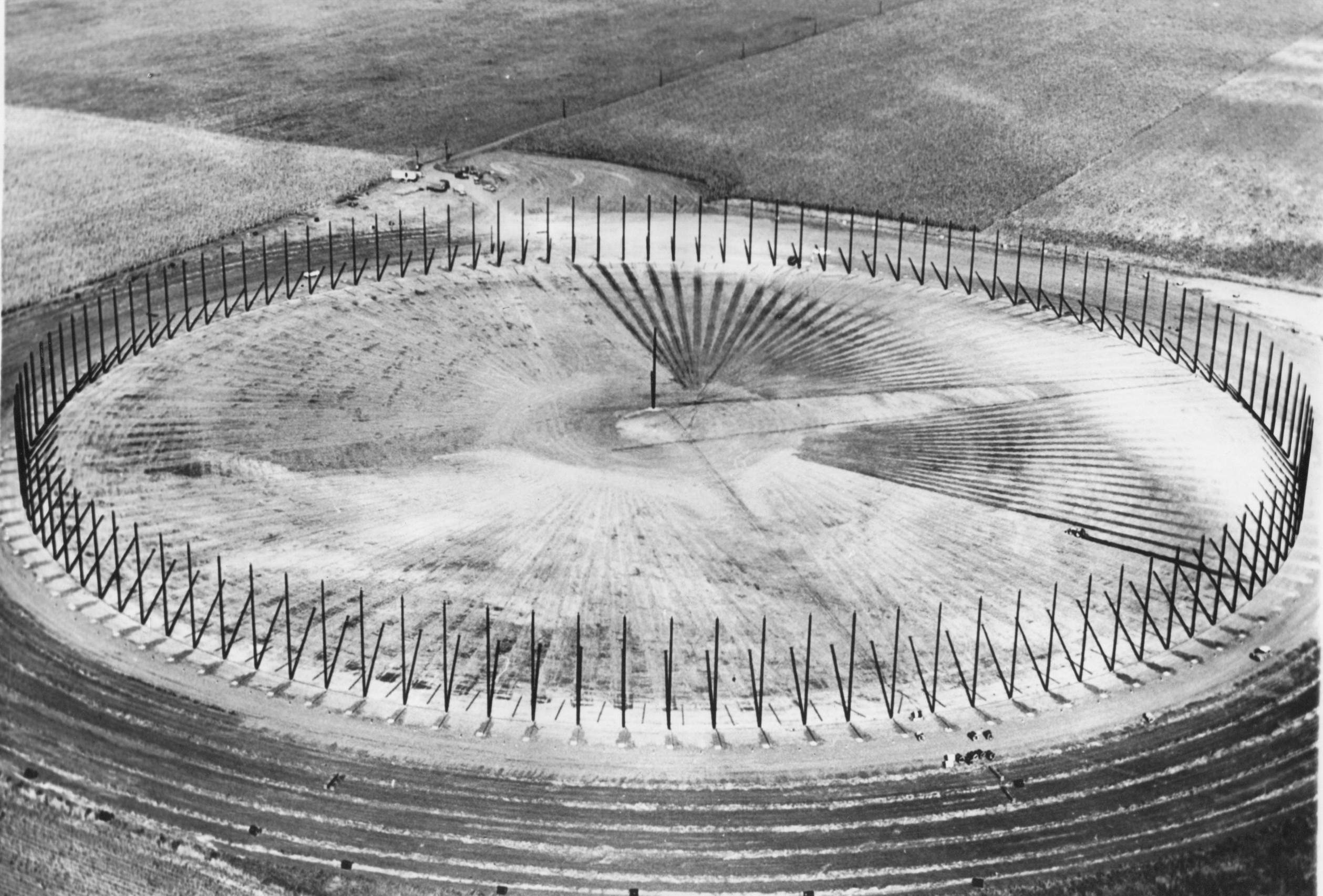
Prototype CDAA at University of Illinois (Champaign-Urbana) - 955' diameter -
120 poles 65' tall
Manuals
Additional References
|
AN/FRD-10 installations at Sugar Grove |
CDAA Major Antenna Components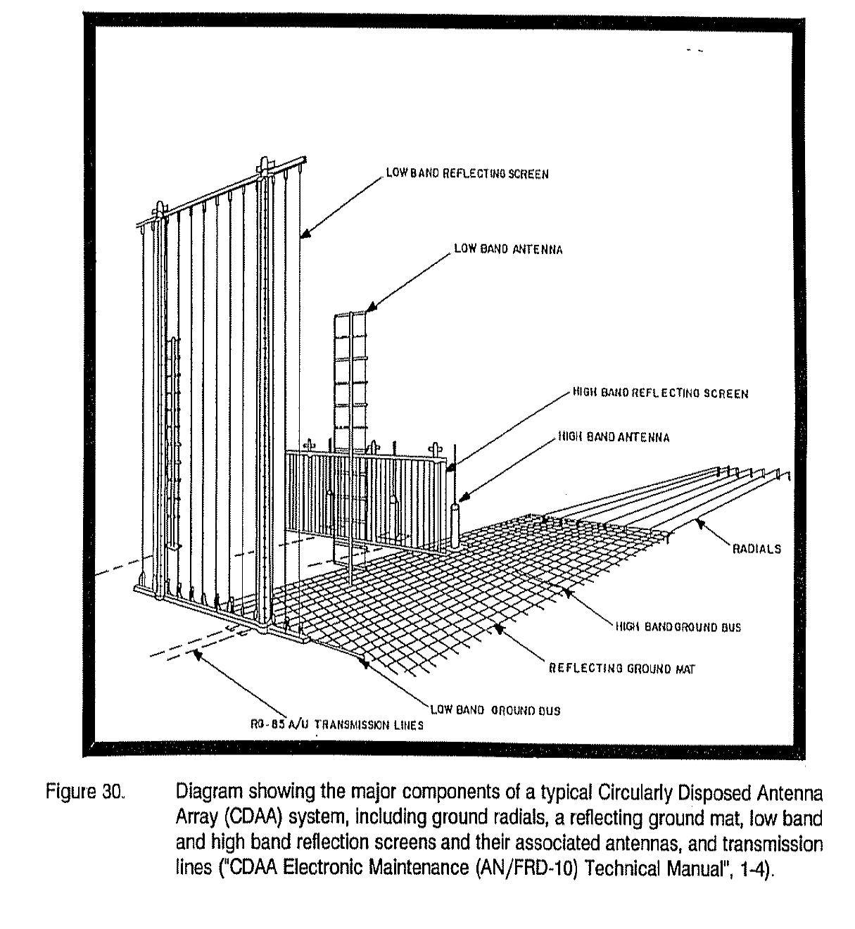 |
CDAA Element Rosette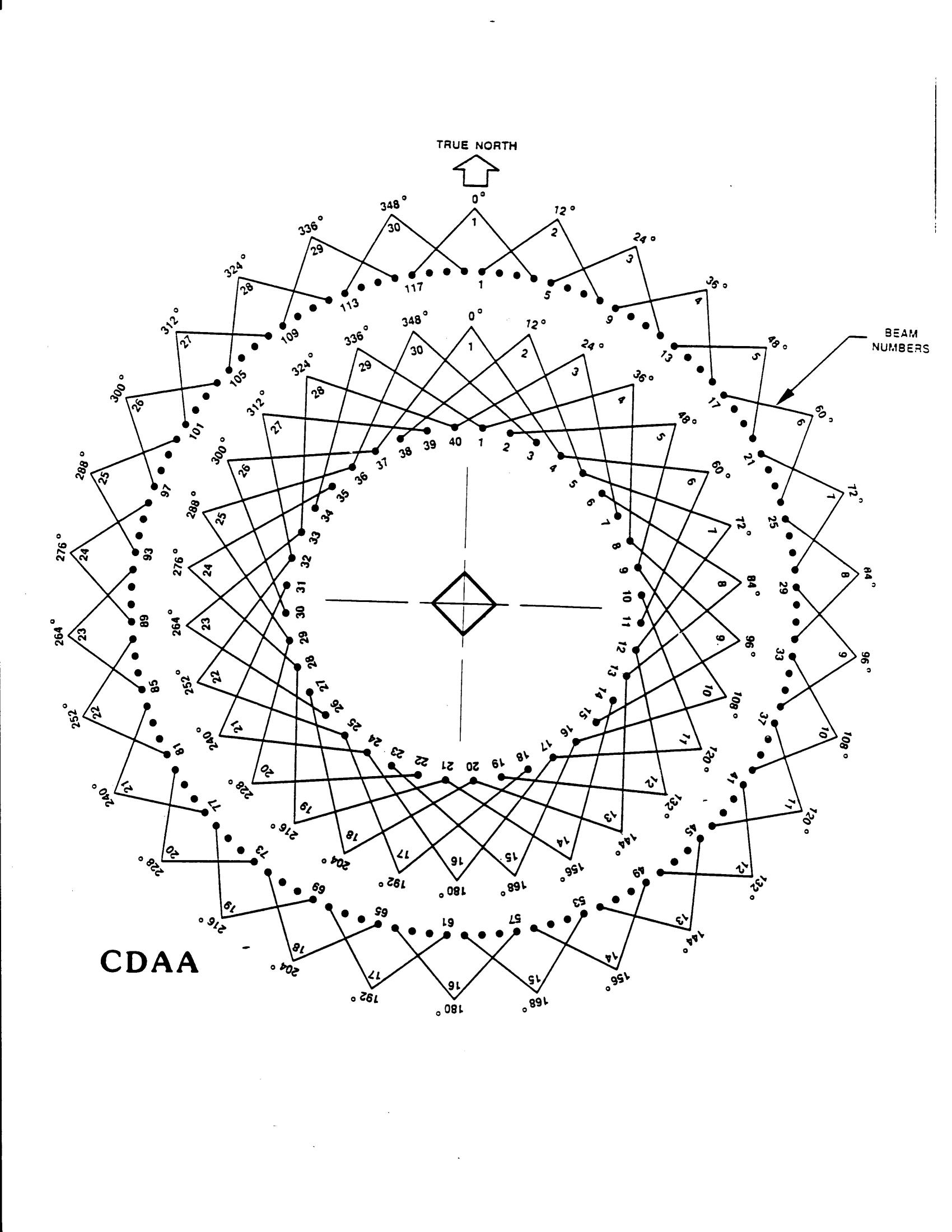
|
|
AN/FRD-10 Imperial Beach - Video photo thanks to Wullenweber/CDAA home page 
|
AN/FRD-10 Imperial Beach (from National Archives) 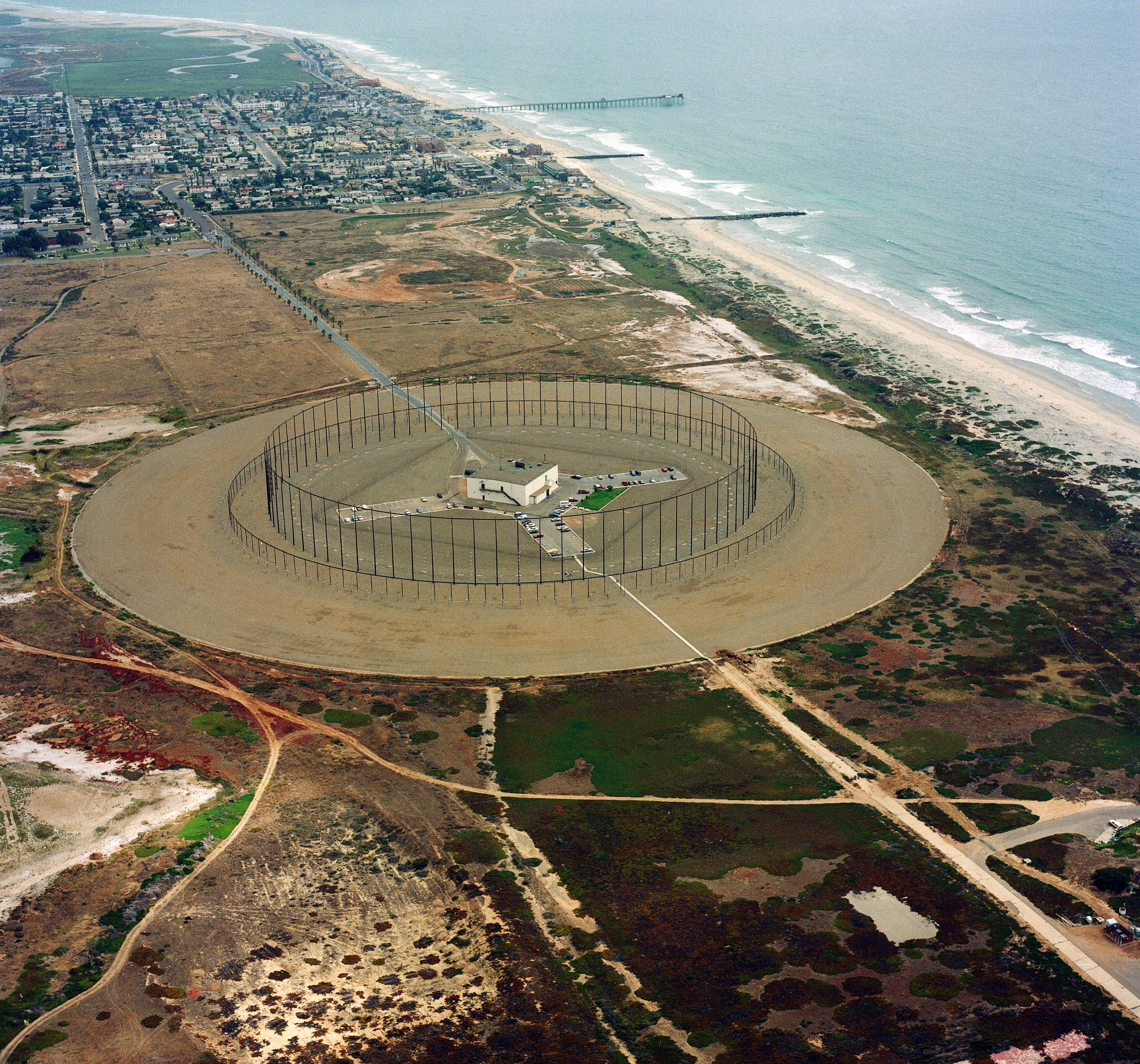
|
AN/FRD-10 Imperial Beach (from National Archives) 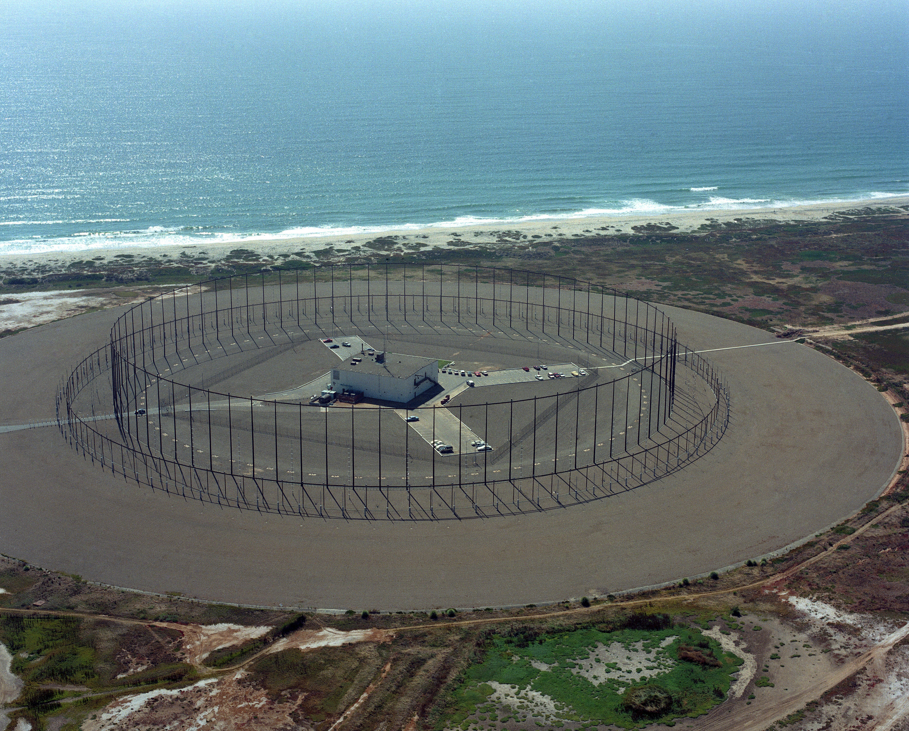
|
|
Nea Makri Greece (NGR) - Mystery CDAA - please send me e-mail with any info on this installation which doesn't appear on any of the usual lists of CDAA sites From an NGR vet - "As I recall, it was a three ringer - sort of a circular fence surrounded by two concentric rows of antennas, taller ones inside shorter ones, and an extensive ground screen all over the place. |
Nea Makri Wullenweber CDAA antenna

Another vet says it was used as the receive side of a diplomatic communications relay station, connecting the State Dept. U.S. communications base with embassies in the mid-east. |
12/68 newsletter
Another vet says it was a CIA operation |
|
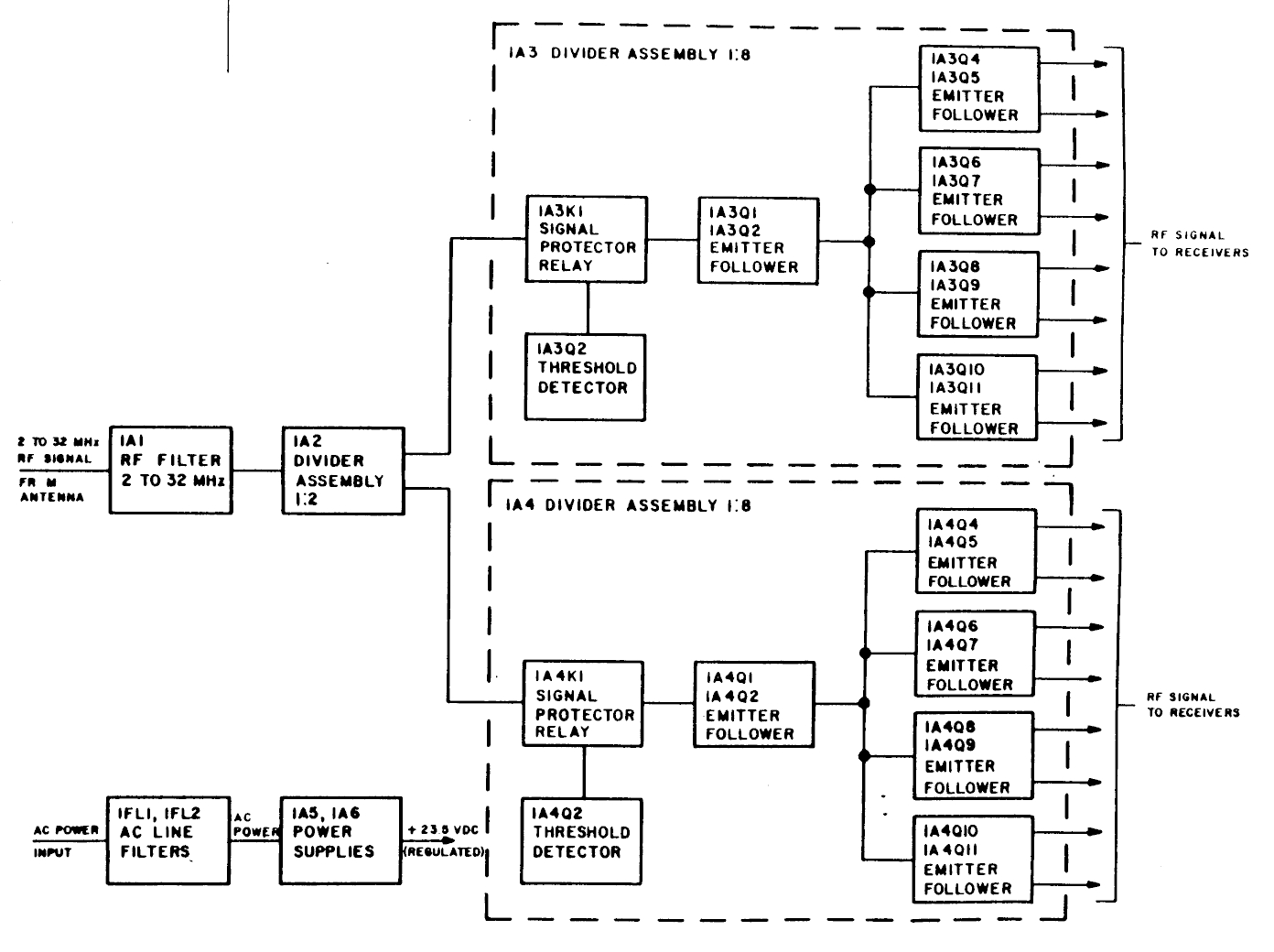
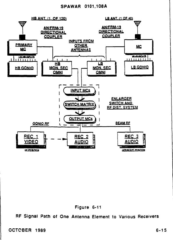
RF Signal Path of One Antenna Element to Various Receivers |
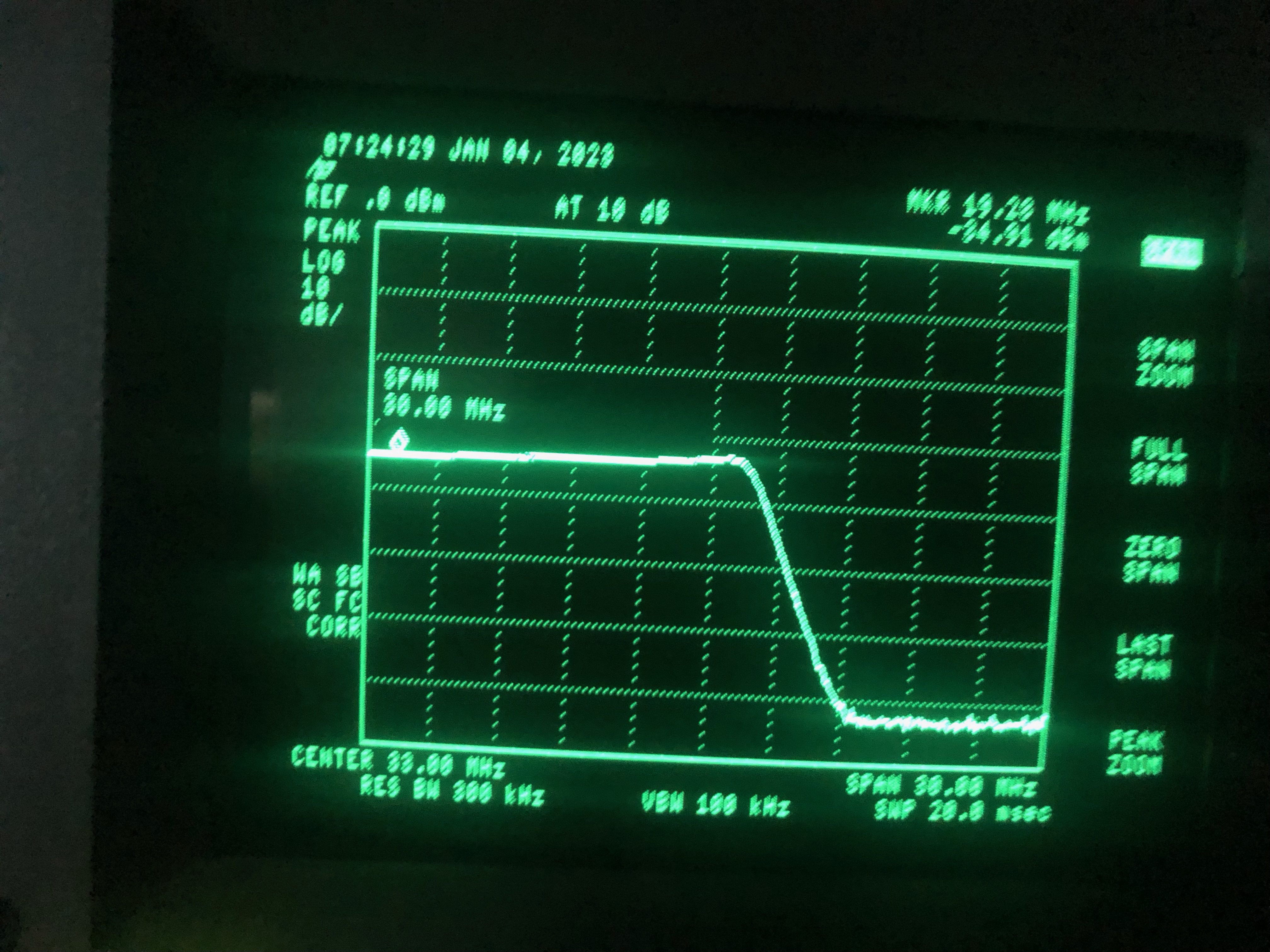
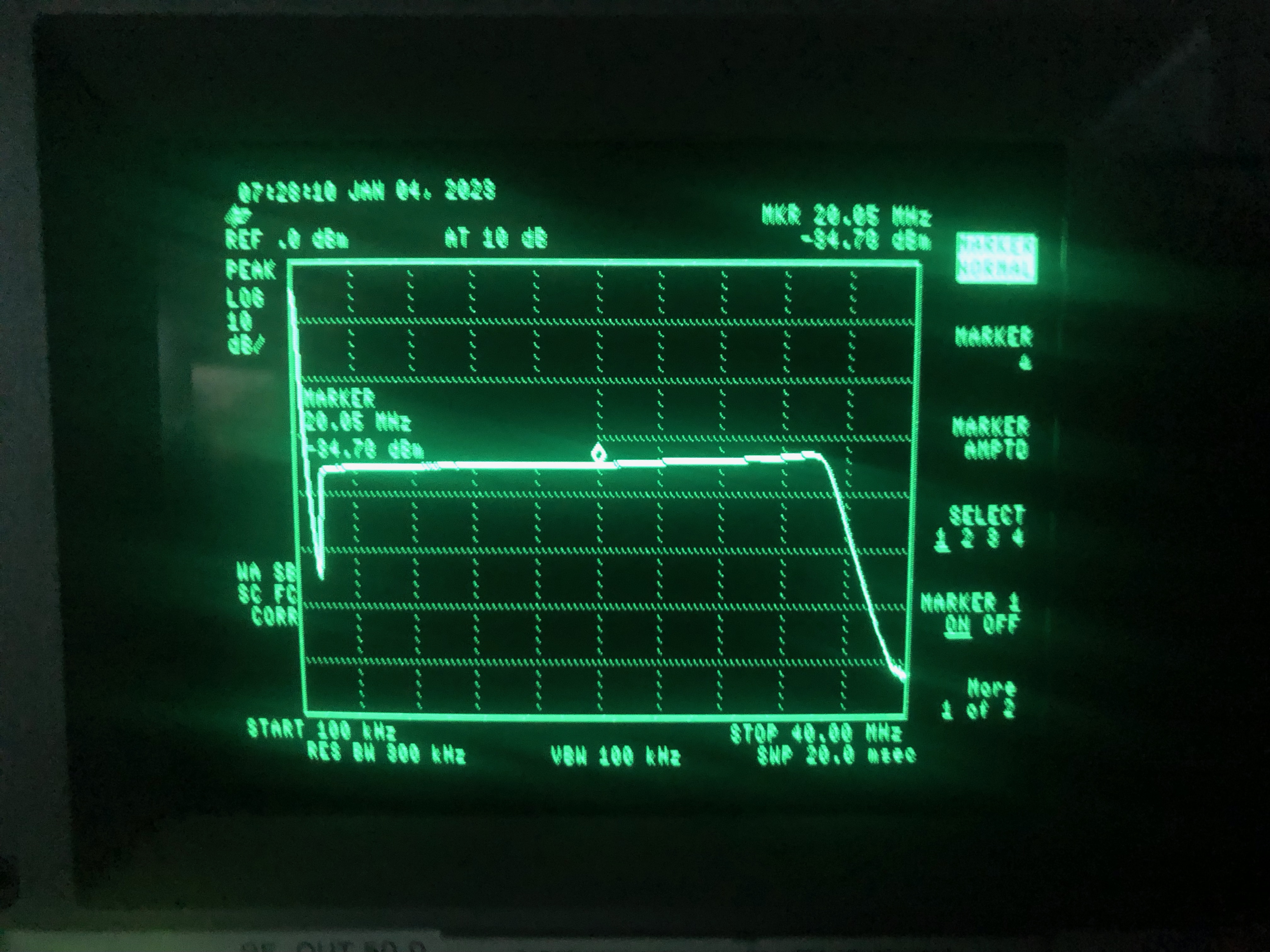
Typical CDAA RF Output Capabilities
|
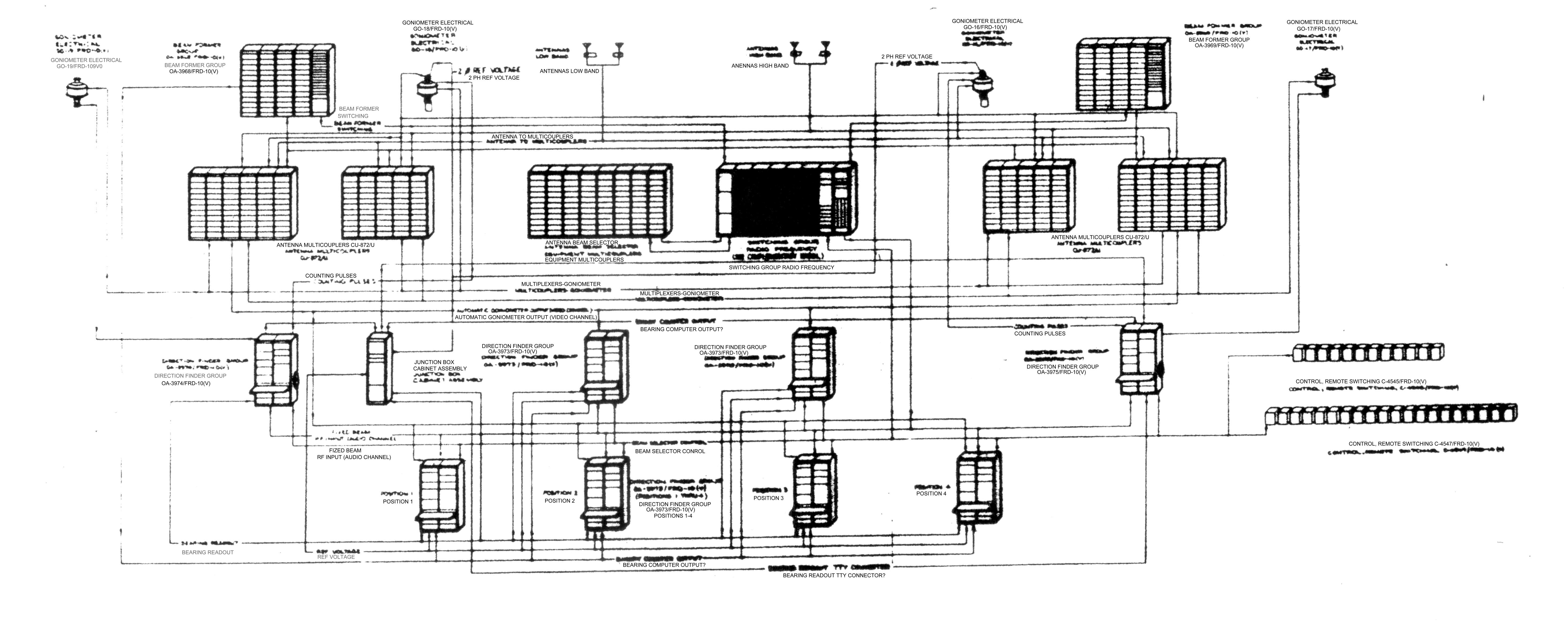
AN/FRD-10 RF Path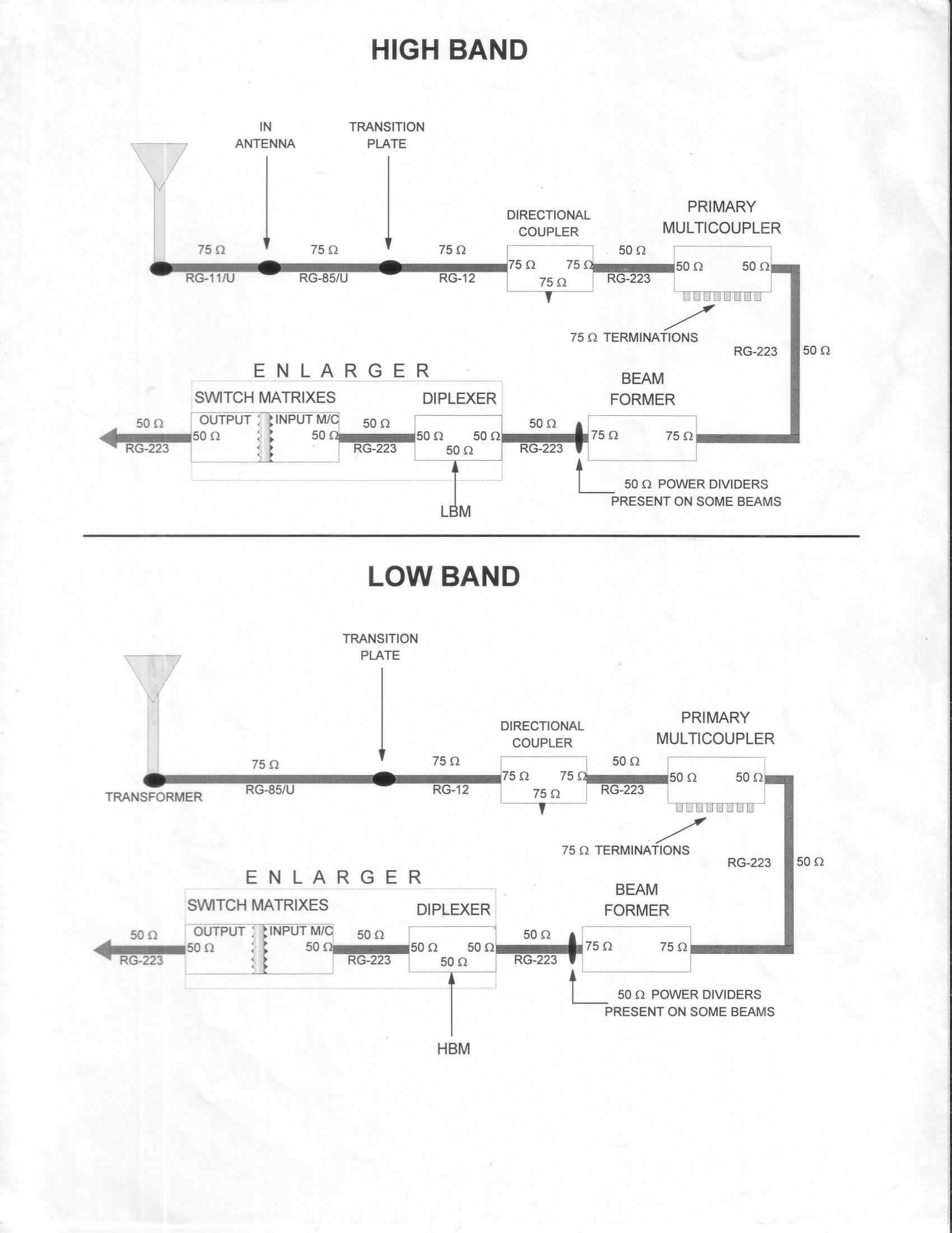
|
AN/FRD-10(V)
|
||
AN/FRD-10(XN-2)
|
||
Photos from Guam FRD-10A site - thanks to Station Hypo |
||

|

|

|

|

|
|
Rate Training Manual photos |
||
 Figure 7-40 CDAA |
 Figure 11-8 Typical CDAA System |
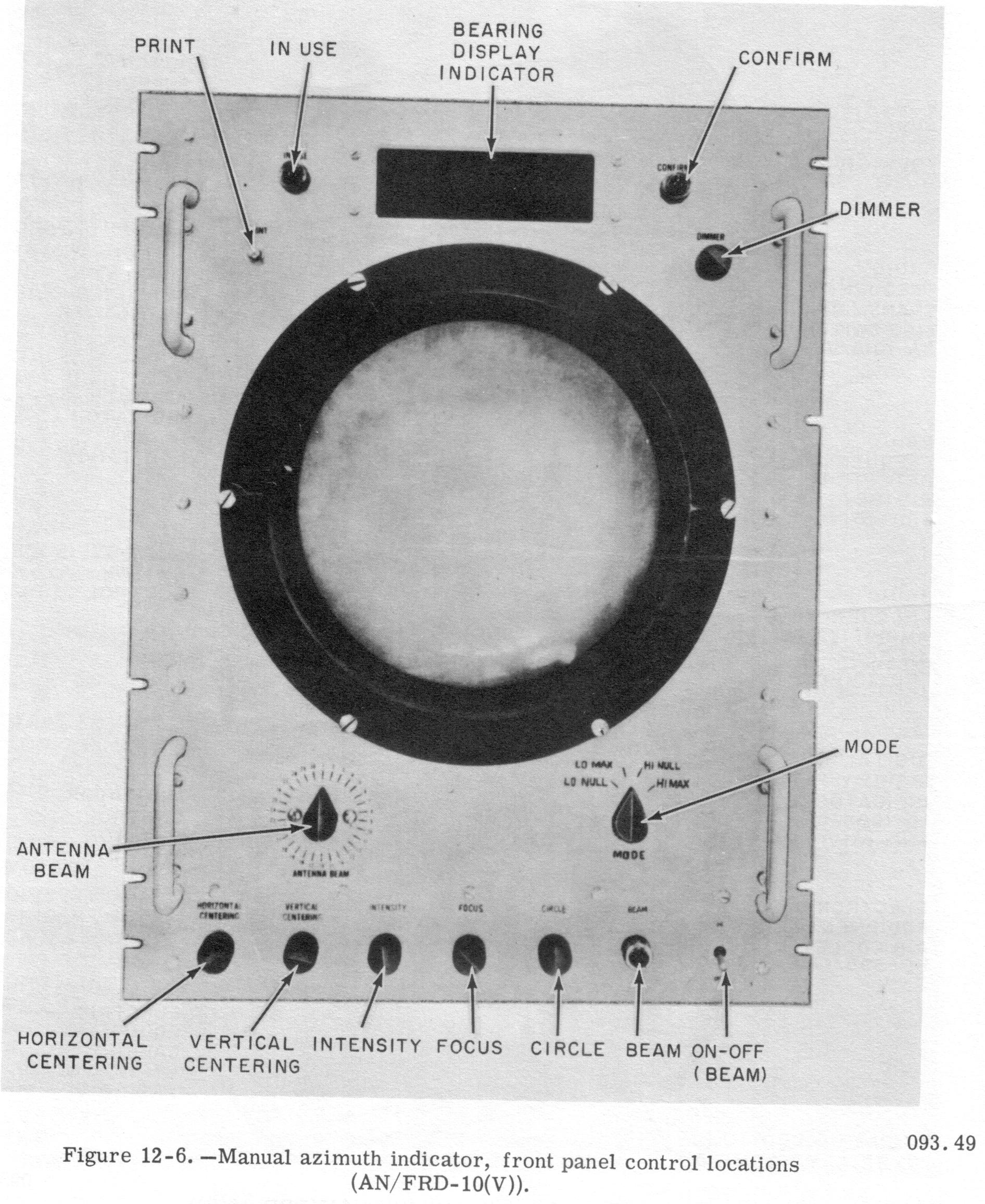 Figure 12-6 Manual Azimuth Indicator |
 Figure 12-7 Channel Watcher Position |
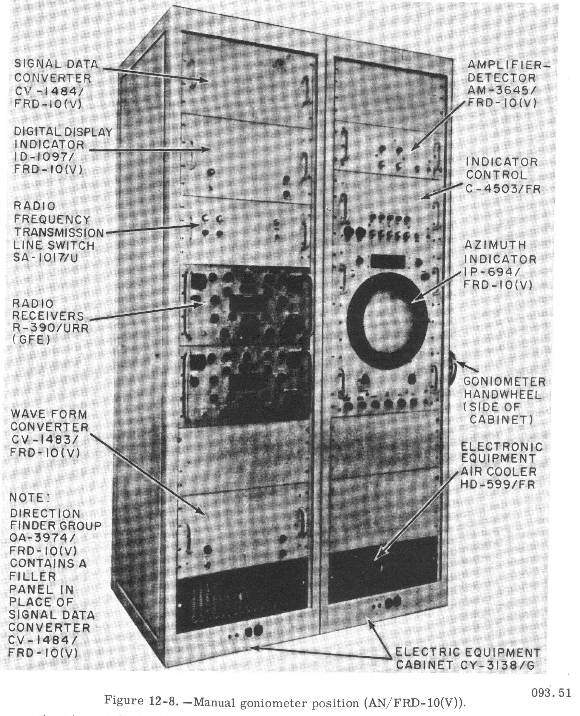 Figure 12-8 Manual Goniometer Position |
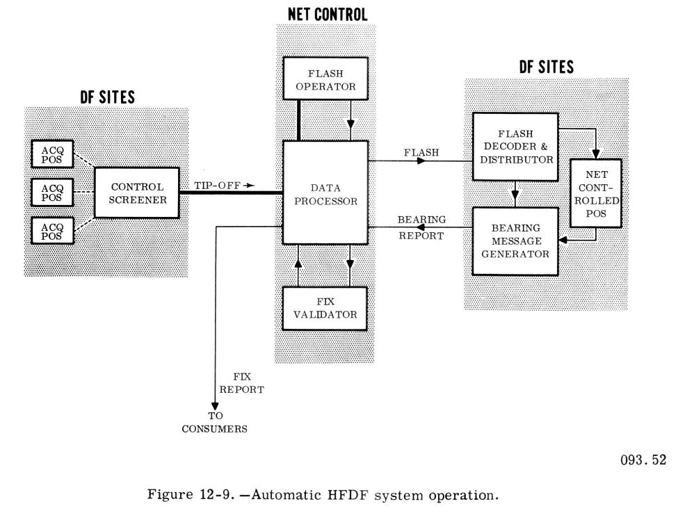 Figure 12-9 Automatic HFDF System Operation |
During the 1950s and 1960s, NRL demonstrated technology that permitted a radical improvement in the performance of high-frequency direction finding (HFDF) networks and oversaw the deployment of this technology in Project Boresight and Project Bulls Eye.
The first of three innovations that underlay this work was retrospective direction finding. Previously, all stations in an HFDF network were required to measure characteristics of the same signal while transmission was still occurring; after-the-fact measurements were needed. Previous attempts at NRL and elsewhere were limited by storage bandwidth and recorder instabilities. Recording significant fractions of the HF spectrum and using a digital method for overcoming recorder instabilities2 enabled retrospective DF. This was the basis of the 1960 quick-reaction Project Boresight that deployed the AN/FLR-7 and AN/FRA-44 worldwide.
The second innovation was the use of circularly disposed wide-aperture direction finding arrays, which significantly increased HFDF location accuracy and signal collection. In the 1950s, NRL constructed a 400-ft diameter electronically steerable array and perfected the underlying technology. During Project Bulls Eye, scaled-up versions of this prototype were deployed worldwide by the Navy as the AN/FRD-10.
The third innovation was the use of computers for control of the HFDF network and for the prompt triangulation of target locations. To achieve high computer reliability in the pre-integrated-circuit era, a novel architecture of closely coupled shared-memory multiprocessors was reduced to practice and was deployed as the AN/GYK-3.
Project Boresight’s crucial contribution to national defense was recognized by the awarding of the Distinguished Civilian Service Award to NRL’s R.D. Misner and M.J. Sheets. The more ambitious Project Bulls Eye deployed the second and third innovations and improved the first with the AN/FRA-54 and the AN/FSH-6, thereby making HFDF a principal means of global ocean surveillance, with special capabilities against critical targets.
Misner, R.D. and Tool, A.Q., “D/F Bearing Recorder,” NRL Memorandum Report 162, May 1953.
Misner, R.D. and Wald, B., “Bearing Readout Systems for Goniometric Direction Finders,” NRL Memorandum Report 830, August 1958.
Trexler, J.H., “Circularly Disposed Antenna Arrays,” NRL Report 3213, December 1947.
Further reading - Boresight, Bullseye, Clarinet Bullseye, Classic Bullseye, Classic Wizard, Enlarger, Centerboard, Flaghoist
CIRCULARLY DISPOSED ANTENNA ARRAY (WULLENWEBER)
The Circularly Disposed Antenna Array (CDAA) consists of a group of omnidirectional antennas symmetrically spaced about the periphery of a circular reflector screen. Figure 7-40 shows two concentric CDAAs- -the outer one a high band array (8-32 mc) and the inner one a low band array (2-8 mc).
The location of each antenna with respect to the screen and to the adjacent antenna is so designed that, by use of a suitable antenna output scanning system, the antenna array provides high unidirectional gain in all directions of azimuth. The scanning procedure results in sweeping the horizon with a direction finding beam through a continuous arc of 360°, thus providing a suitable HF direction finding antenna system. The CDAA system can also be connected to fixed-lobe-forming devices that provide fixed directional beams for receiving signals in any desired direction of azimuth.
Either a wide or narrow beamwidth can be obtained by proper selection of certain antennas in the array. These antennas would be located in the segment of the array
which faces the direction of interest. The outputs from the fixed lobe devices can be used for communication receiving. The CDAA, also called the
Wullenweber, is a high gain antenna system with extremely flexible usage.
CIRCULARLY DISPOSED ANTENNA ARRAY
The circularly disposed antenna array (CDAA) system, explained in chapter 7, is a more recent development than any of the antenna systems previously discussed. The CDAA system has some signal gain characteristics which make it much more desirable than any other system used for direction finding. These gain characteristics are particularly greater than those of previously designed systems for use in the h-f band.
As was explained in chapter 7, the CDAA consists of a group of omnidirectional monopole antennas symmetrically spaced about the periphery of a circular reflector screen. Most installations consist of a double ring array; one within the other. The outer ring consists of 120 vertical elements for the 9 through 30 mc band and is 863 feet in diameter. The inner ring consists of 40 vertical elements for the 2.5 through 9 mc band and is 787 feet in diameter. Each ring has its own reflector screen. The reflector screen serves to provide some degree of directivity to each individual antenna and to improve the gain characteristics. By electronically combining groups of antenna elements, further directivity is obtained. Each antenna element is connected to a multicoupler by coaxial cable. The maximum signal is obtained by scanning the outputs of the antenna elements, around the circle. The output of the scanning system is greatest where it sweeps through the sector having high forward gain in the direction of the target transmitter.
The output of the goniometer (scanning device) at any angular position is actually the output of a monopole array -the combination of several of the monopole elements- rather than the output of a single monopole element. The resultant response will have a high forward gain (considerably greater than one) when compared to a monopole of the same dimensions as the individual antennas of the system. The output signal developed by Adcock antennas, however, is actually the difference in signals of two mono pole elements-- the vertical components of the antenna. This means that the directional gain of an Adcock antenna is small (much less than one) when compared to a reference monopole of the same dimensions as the vertical elements. Therefore, the CDAA has a very large increase in gain over the Adcock antenna. Bearings may be obtained on incoming waves of much weaker strength and poorer quality when using the CDAA than when using Adcock antennas, thereby allowing DF bearings to be obtained on transmitters much more distant from the DF site.
The block diagram of a CDAA system which could be used is shown in figure 11-8. The system would serve all radio receiving needs
at a particular site- within the frequency limitations imposed by the antenna elements. The block diagram shows a system designed for use with two
arrays, a low band and a high band. The operation of each band is identical except for the frequency range covered.
In the system shown in figure 11-8, each element of the array is connected to a multicoupler which has three outputs. Two of the outputs go to
goniometers- the output scanning devices. The third output goes to fixed lobe boxes. The outputs of the fixed lobe boxes can be used for communication
receiving.
AN/FRD-10
ANTENNAS
A far more versatile antenna than the U-Adcock, and one that is even more accurate for DF purposes is the CDAA which was discussed in some detail in chapters 7 and 11. The CDAA consists of two concentric circular arrays of vertical elements. By bringing the outputs of the elements to a rotating goniometer, the effect produced at the goniometer output is similar to a single narrow beam scanning the
azimuth. The direction of arrival of the target signal is indicated on the
cathode ray tube indicator as a single bearing pattern and also as a numerical indication on the bearing display indicator (see figure 12-6).
RECEIVING AND BEARING INDICATING EQUIPMENT
Three types of DF positions are provided with the AN/FRD-10. These are; the net controlled or auto-tune position, the channel watcher position (see figure 12-7), and the manual goniometer position (see figure
12-8). A typical installation consists of two auto-tune positions, each covering the entire 2 to 30 megacycle band; two
channel watcher positions, each covering the 2 to 30 megacycle band; and the manual goniometer position, with a high band equipment and a low band equipment.
The auto-tune position, which contains a receiver capable of remote rapid tuning on command, is the "workhorse" of the DF system.
The channel-watcher position functions as a monitoring DF position with long term DF assignments and as an alternative net controlled position during
peak loads. The manual positions are equipped with manually tuned receivers and manually rotated
goniometers. Because it is manually rotated, the goniometer rotational rate is very low permitting narrow bandwidths to be used on the receiver.
The primary use of the manual position is in a noisy signal and high interference environment where narrow receiver bandwidth can improve signal
selection.
THE U. S. NAVY AUTOMATIC DF SYSTEM
The Navy HFDF system is constantly striving to find new equipment and methods of operation to keep pace with future communications developments. The basic objectives are to provide increased accuracy, faster response of DF bearings, and greater capacity for obtaining fixes on target signals of interest.
To meet these objectives a system has been developed to provide fully automatic operation of the DF nets. Comprising this system are three so-called sub-systems, each performing a separate but related function. These three sub-systems are: (1) the acquisition sub-system, which locates and screens desired targets for the net; (2) the DF sub-system, which consists of the various direction finder sites in the net that actually obtain the bearing information; (3) the data transfer sub-system, which encrypts and transmits target information to the net, receives and decrypts bearing information from the net, and analyzes and disseminates that information.
THE ACQUISITION SUB-SYSTEM
The acquisition sub-system functions are primarily limited to furnishing, in a timely manner, sufficient data on target signals to permit unambiguous
bearing measurements throughout the net. The acquisition sub-system is comprised of acquisition positions located at any of the actual DF sites. In addition, each site having acquisition
positions has a position manned by an operator called the Control Screener. Its function is to process into
tip-offs (a short message to Net Control) information on target signals found active by the acquisition positions at that site. Capability of measuring target signal frequencies to a high
degree of accuracy is provided. This capability, combined with the accurately tuned DF receiver, enables all DF stations to tune to the precise signal
frequency and help prevent wild bearing reports. The acquisition subsystem is improved by the addition of machine aided message preparation equipment. This equipment, as in the DF sub-system, permits
more rapid preparation of messages and assures proper format for entry into the data processors located at Net Control.
The major improvement of the automatic system is the inclusion of a high speed digital computer at each Net Control site.One of the tasks assigned to the computer is that of fix computation which must be fast and accurate. The computer is programmed to compare each line bearing with such factors as station accuracy and bearing scatter in order to arrive at a statistically determined best point estimate of target location along with a confidence area about this point. While the computations required are extensive, the process takes less than a second to perform. Accuracy of the fix is similarly improved since the sometimes questionable weighting applied by human fix plotters is eliminated.
The computer performs the task of determining the accuracy of the individual DF stations to report bearings, and time required from flash-to-fix for the net. The computer also serves to reduce the amount of manual processing required in performing such functions as processing tip-off messages into flashes. This function is not completely automatic but with the filtering provided will reduce, for example, duplicate tip-offs.
Preparation of daily reports is another function that the computer is ideally suited for and, considering the increased data rates that the system must handle, it is obvious that many man hours of effort will be saved by the computer. It is apparent that with the high speed computational capability frequency propagation predictions can also be performed by the computer. This information could provide guidance to the acquisition sub-system concerning potentially active frequency bands, information on lateral deviation for use in the fix computation process, and guidance to the data transfer sub-system as to when frequency shifts should be made.
THE DF SUB-SYSTEM
The existing DF sites are programmed for improvements by modification or replacement of present equipment with completely new
equipment. The AN/FRD-10 direction finding equipment and associated circularly disposed antenna array will be used almost exclusively for this purpose.
This system features an instrumental bearing accuracy of one tenth degree, and an estimated standard deviation of one degree. The latter figure represents a three to one improvement over that obtained with the AN/GRD-6 system. Another improvement, that of sector scanning, can be accomplished with the CDAA through the use of an additional spinning goniometer. With this technique, the same quantity of samples can be obtained on the signal of interest with a slower goniometer rotation rate thus permitting narrower bandwidth operation. Automatic bearing measuring equipment is included in the DF sub-system also. This feature, whose use in lieu of manual bearing measurement is the prerogative of the DF operator, furnishes a statistical measure of both the mean bearing and the standard deviation of the bearing scatter. The latter is of particular importance as a weighing factor in fix determination and a measure of this factor results in a more accurate estimate of target location. An accurate and reliable command tuned receiver is included within the sub-system. This receiver is capable of tuning, in one cycle increments, to an accuracy determined by the station standard. The high accuracy of this receiver, coupled with comparable frequency measurement accuracy in the acquisition sub-system serves to simplify the signal verification problem and greatly reduce the "wild bearing problem. "
Another feature of the DF sub-system is the incorporation of machine aided message preparation equipment at the various operating positions. Provided at these positions are buttons for each of the major items of the bearing report requiring decision on the part of the operator, as well as a button which initiates read-out bearing measurement. Other items of the report, such as flash number, are automatically included in the message and require no action by the operator. With this feature speed of response is enhanced and the message format required by Net Control Data processing facilities is assured.
DF Sub-Systems Equipment Operation
When a flash is transmitted from Net Control, a flash decoder at the DF station routes the flash to an idle net
controlled position. If all the positions are busy the flash is stored in the decoder until one of the positions is able to handle the bearing request. The flash
message that is routed to a net controlled position automatically tunes the receiver to the desired frequency and prints out the call sign and
identification portion of the flash on a teleprinter located at the selected position.
The operator then obtains a bearing on the flash target and reports this by an automatically generated bearing report, or "no bearing" which is also
reported automatically. In case the target signal indication is obscured by noise or interference, the flash may be switched over to the manual
position where the narrower bandwidth capability might produce a bearing.
The operator, after having set his alidade or indicator to the best bearing, prepares a bearing report by depressing bearing quality, identification, and readout buttons. When the operator has depressed his readout button a message is automatically prepared by equipment called the Bearing Message Generator. Upon depression of the readout button at the DF operator's position, the Bearing Message Generator senses this signal as a command to collect the bearing report. It obtains the flash serial number and priority from the memory portion of the flash decoder, the bearing information from the DF position, and inserts the necessary machine characters to indicate start and stop of the message. The flash priority is not transmitted with the bearing report but is used only to determine the order of transmission of the bearing reports. The Bearing Message Generator, after storing the bearing report in a portion of its output store in priority order, indicates by a signal to the encoding equipment of the data transfer subsystem that a message is awaiting transmission.
The Data Transfer Sub-System
The use of an integrated data transfer system represents a major advance in HFDF operation.
The data transfer system utilizes sixteen frequency-division multiplexed channels. The system operates in the HF band using single sideband. Each
channel is capable of handling teletypewriter transmissions of 100 words per minute. By transmitting simultaneously on more than one frequency,
frequency diversity is provided. Such diversity is essential to assure maximum possible reliability. Full on-line crypto is utilized for all data transfer including administrative and
orderwire circuits as well as data bearing traffic. The equipment for this application encrypts on a bit by bit basis and also furnishes a random bit
stream during periods of traffic lulls. This latter feature provides for traffic analysis immunity, thus preventing, for example, detection of system
data handling rates.
AUTOMATIC HFDF SYSTEM OPERATION
(Refer to figure 12-9). When a signal of interest is noted active by an acquisition position, the information is passed to the control screener
position. If the control screener elects to tip-off net control, the send button is depressed. Message preparation equipment routes the properly
formatted message to the data transfer system data is assembled with the assistance of machine-aided message preparation equipment and is transferred on command of the operator to the bearing
message generator. This unit combines the bearing data with the appropriate flash number into a properly formatted hearing report, which is transmitted to Net Control
where, upon receipt, the report is entered into the computer memory system and filed by flash number.
After a sufficient number of reports are collected on a flash, the computer estimates the most likely location of the target and a probability area about this location. This data along with information on the last fix on the target and the number of bearings contributing to the current fix is visually displayed to the person acting as Validator. The Validator may reject the fix on the basis that more bearings should be used in which case the computer is instructed to wait for additional bearings and recompute the fix. The Validator can also accept the fix, of course, and in this case the computer is instructed to prepare fix reports for distribution to the appropriate consumers.
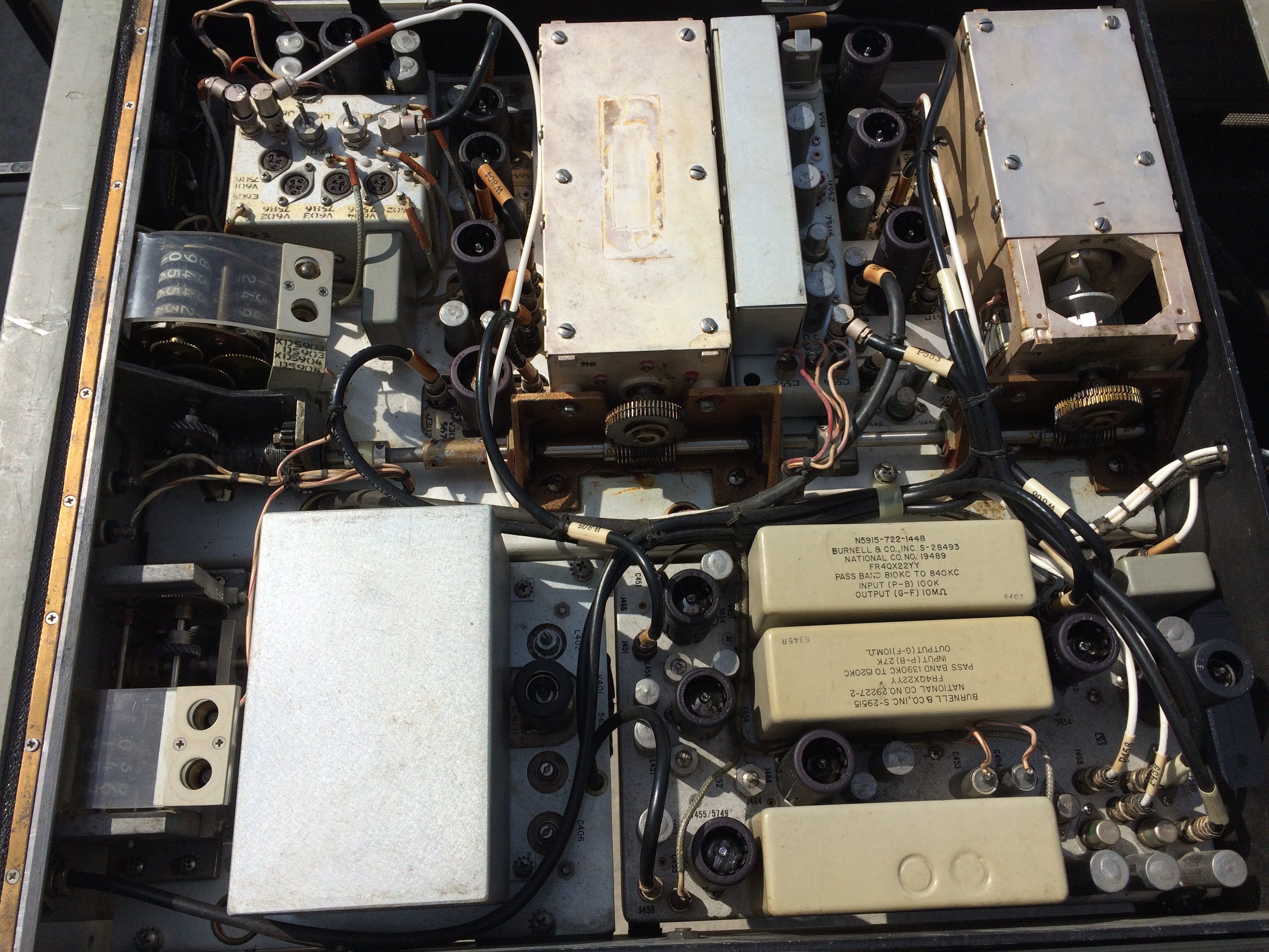
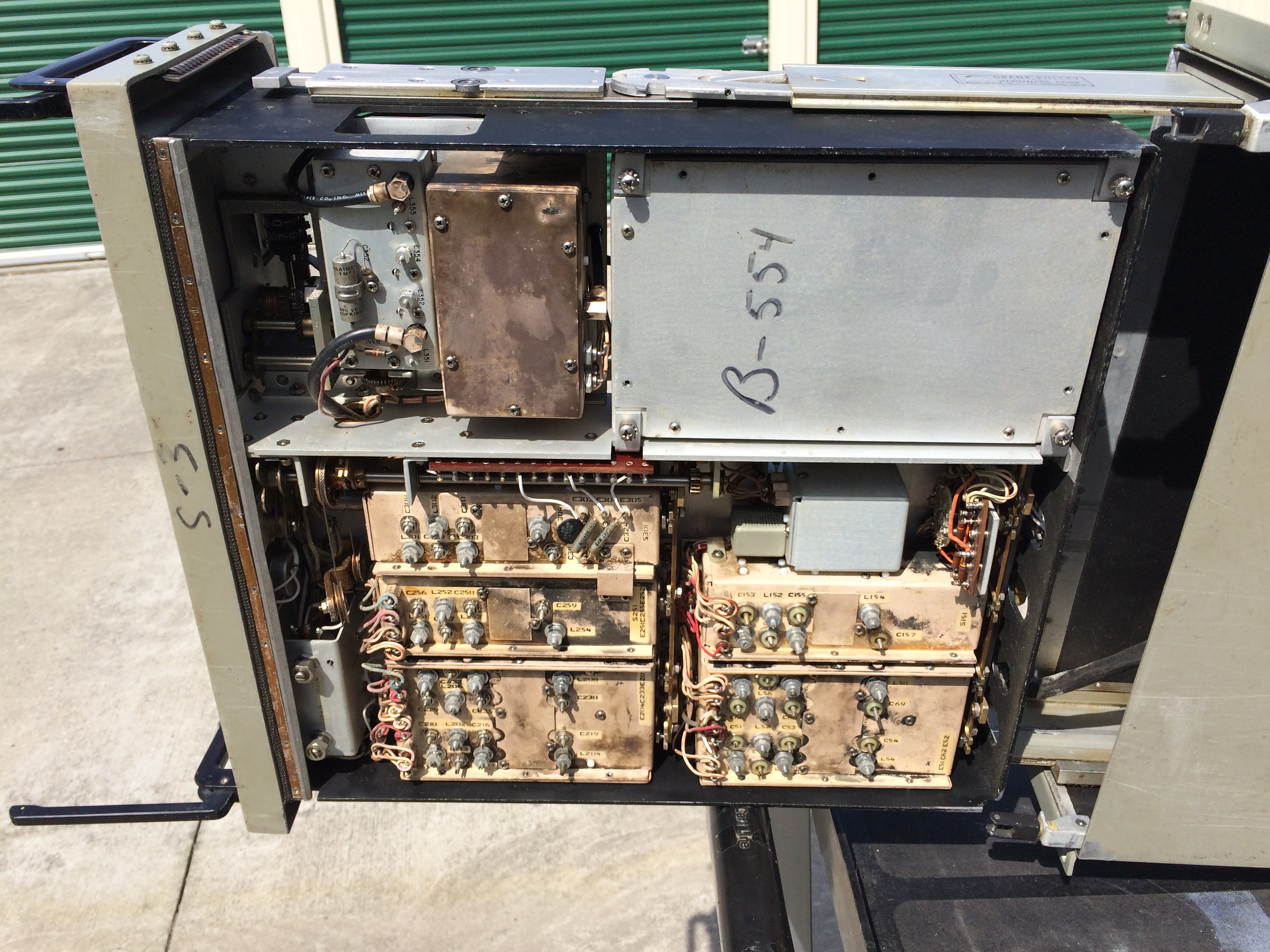
Some AN/FRD-10 COMPONENTS
|
|||
Receiving Equipment |
|||
| R-390A/URR Receiver - photos and info | |||
| R-391/URR (MOD) for AN/FRA-44 and AN/FLR-7 - note no bandwidth switch | |||
 |
 |
 |
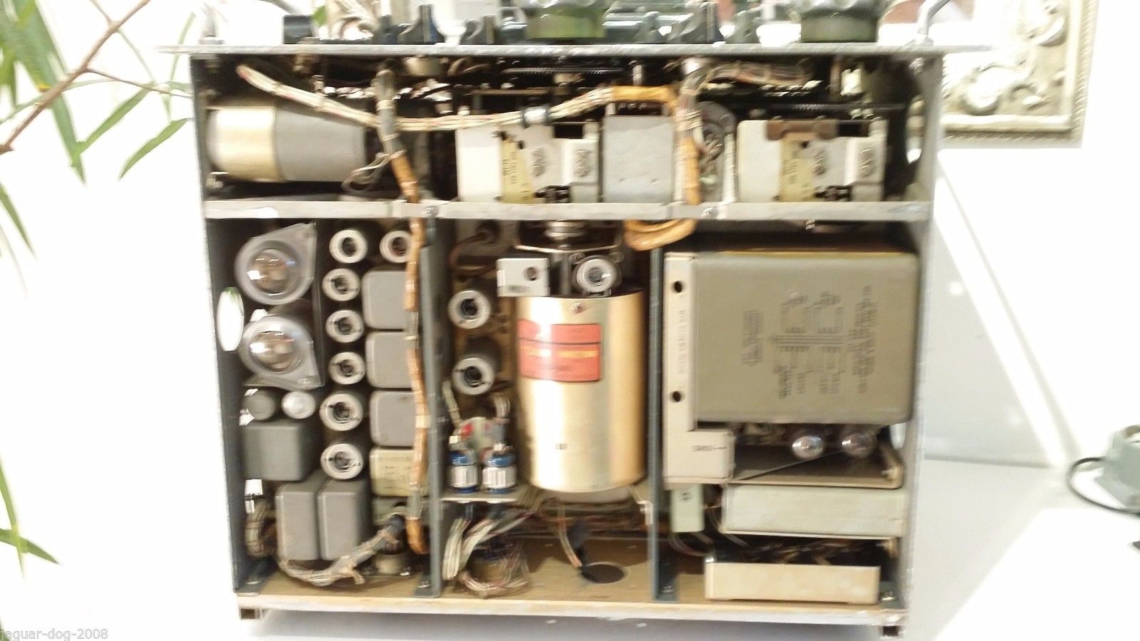 |
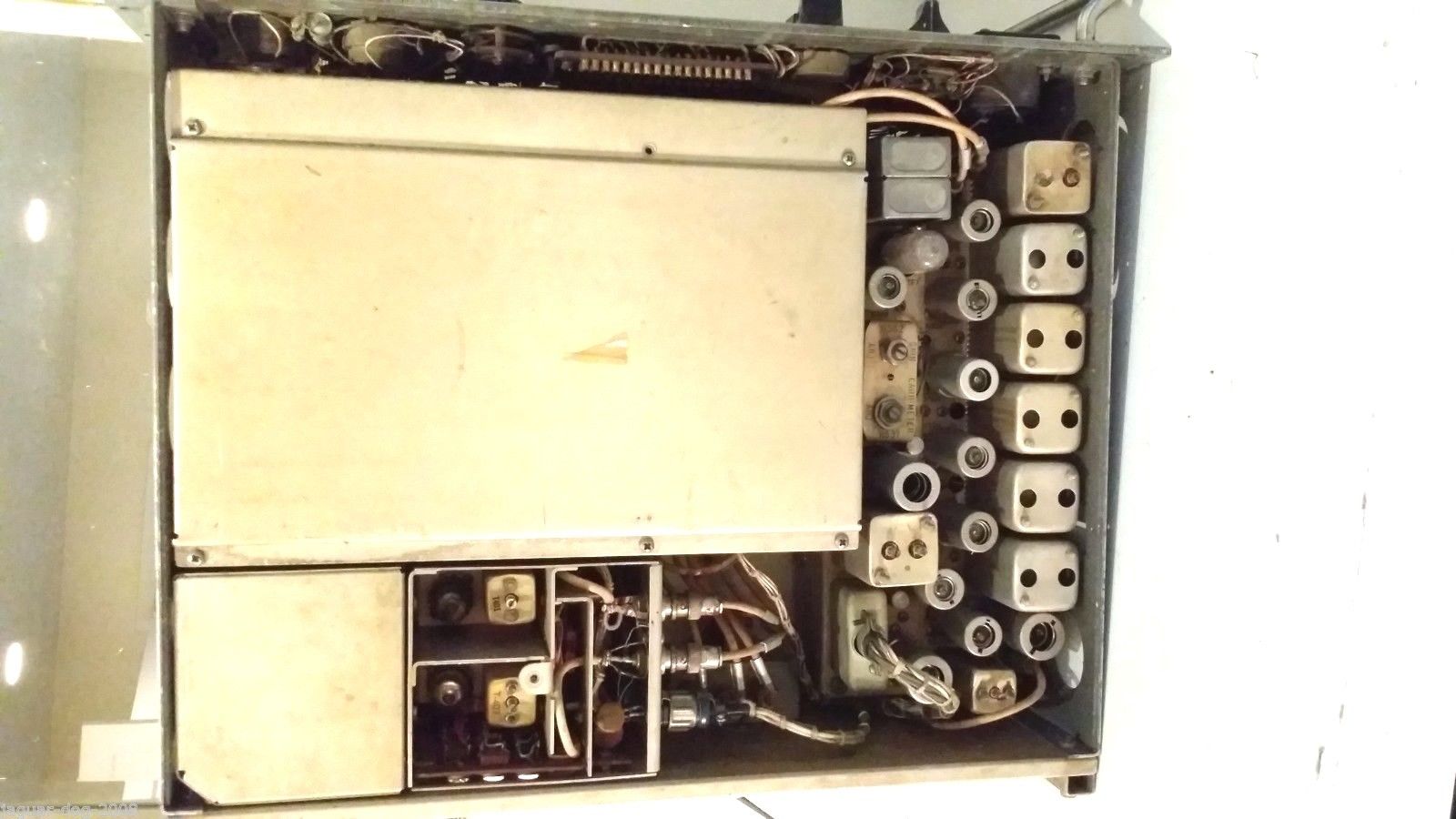
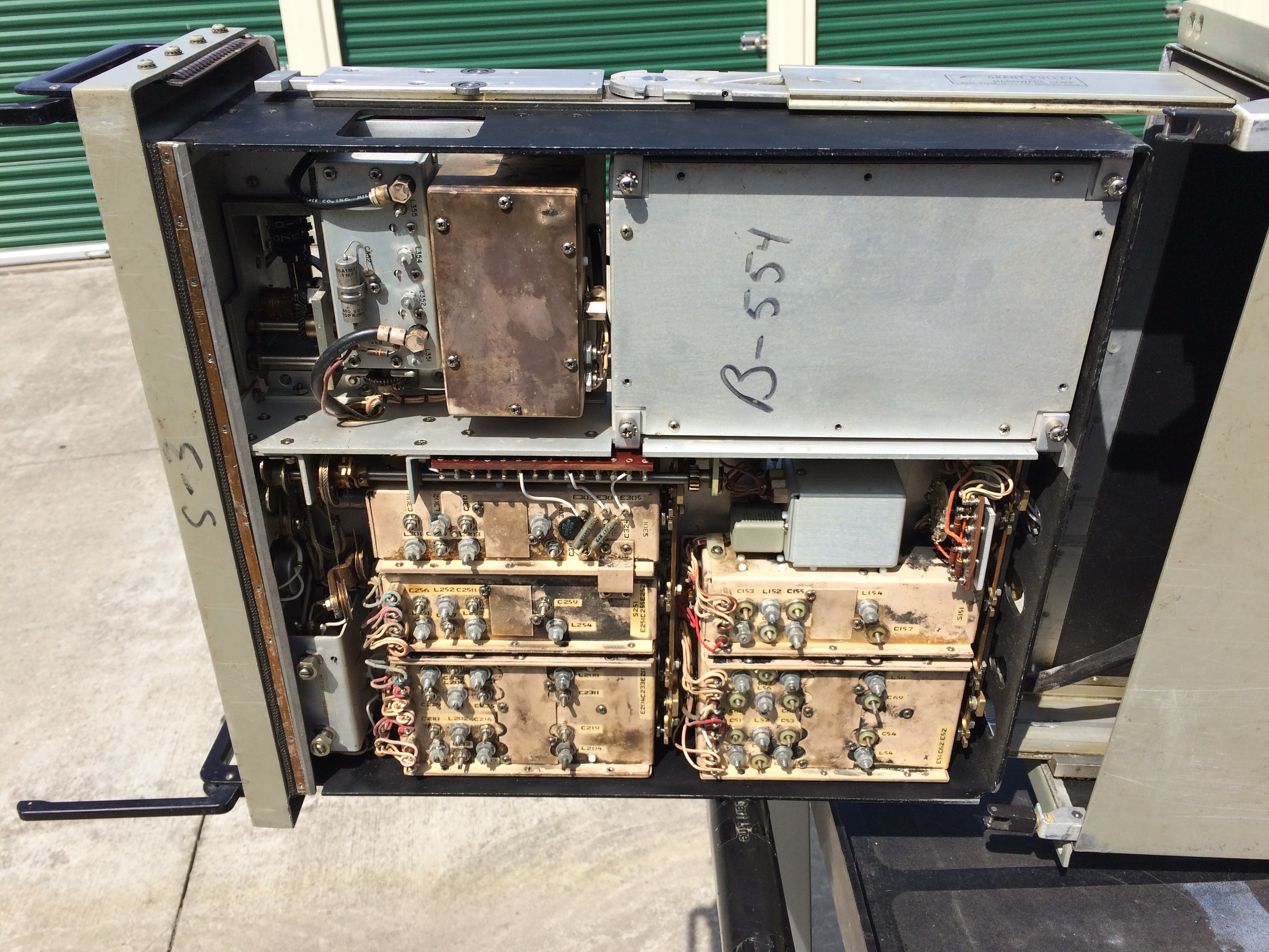
| R-1230/FLR and R-1125/FLR - 2-32 mc coverage with 60kc bandwidth output - triple
conversion Used in AN/FLR-11 and AN/FRA-54 systems |
|||
|
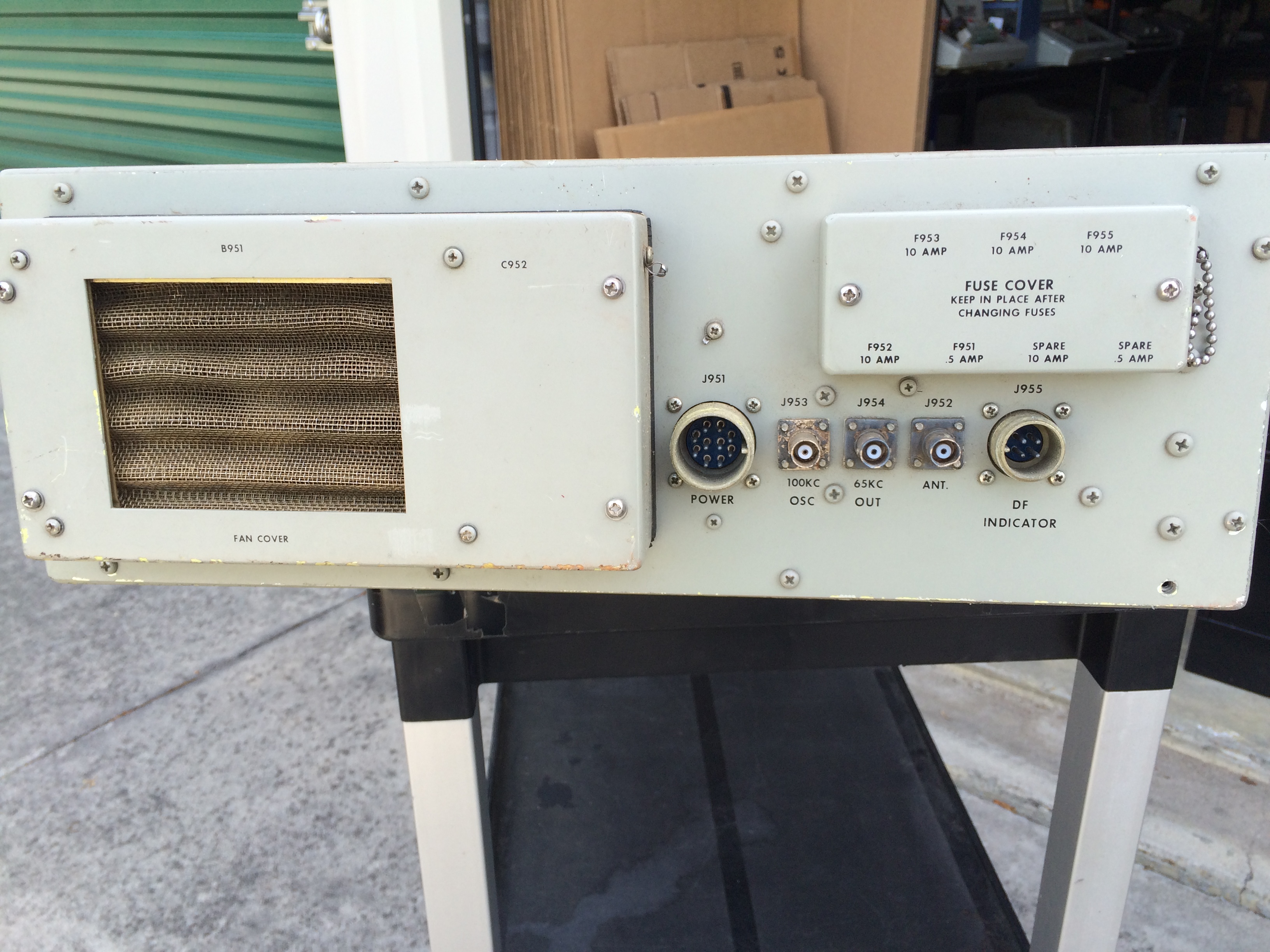
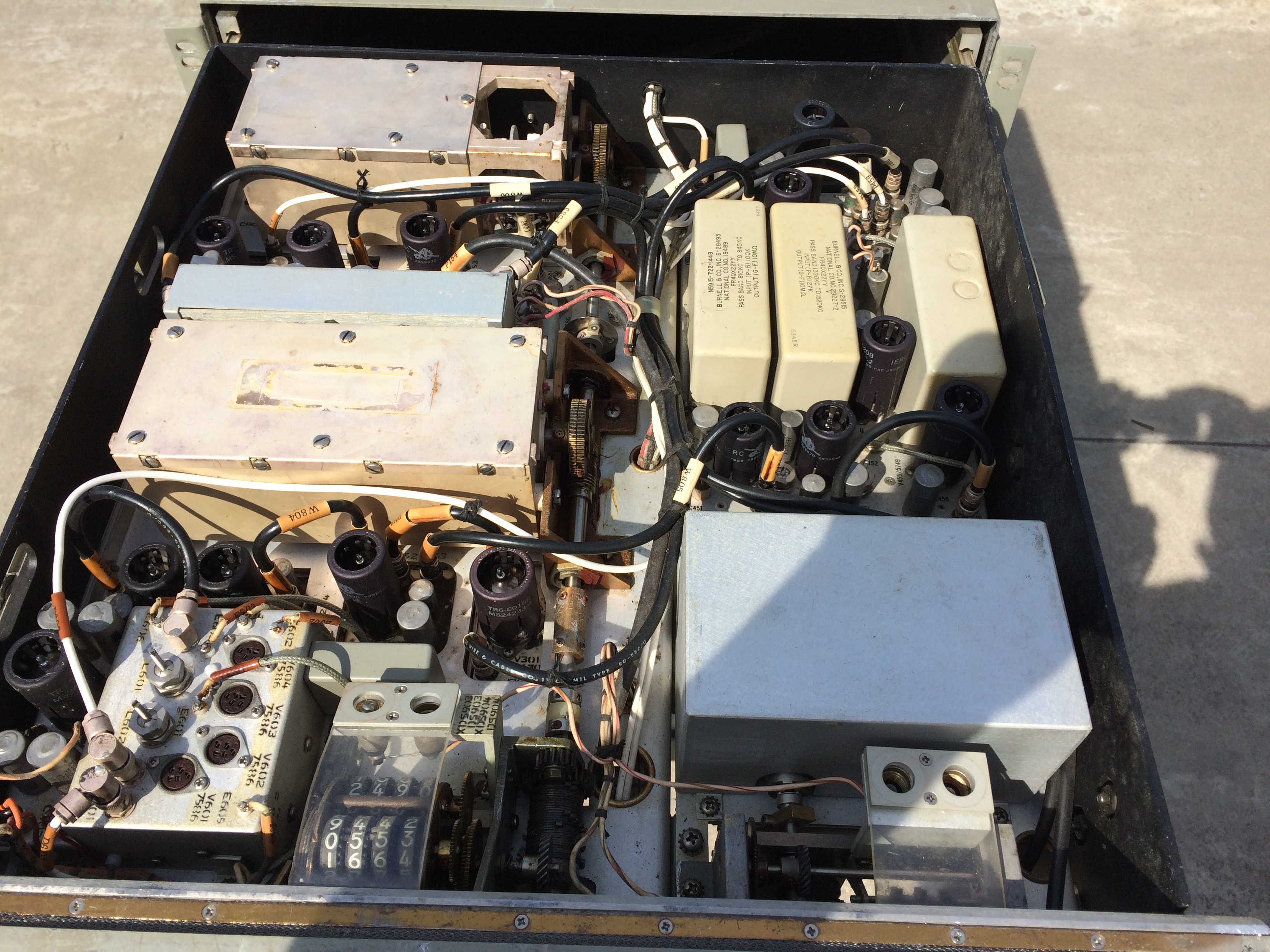
The complete system consisted of two units, one with the RF/IF circuitry and another with the power supply O-928/FLR. The power supply unit was used to power up to 5 RF units and also provides a 100kc reference signal. The power supply section very rarely shows up as surplus. Designed by National Radio. Uses nuvistors as well as miniature tubes. The earlier R-1125/FLR was upgraded to R-1230/FLR via a field change which added a cooling fan. More photos/info - link |
|||
|
Countermeasures Receiver R-1125/FLR is a high-frequency, superheterodyne receiver employing
triple frequency-conversion for the reception of signals in the frequency range from 2.0
mc to 32.0 mc.
It is intended for use in special operating categories and provides a 65 kc output signal
having a 60 kc bandwidth. Receiver operation is characterized by extreme frequency
stability, permitting long periods of unattended operation. A high level of
performance can be
expected despite adverse conditions. Initial tuning is obtained
in 100 kc increments with an interpolation oscillator (in the receiver)
which provides continuous tuning between increments. The
frequency range is covered in four bands with counter-type
tuning dials which permit accurate pre-setting to a desired frequency. A special drift-canceling
circuit contributes to the receiver's high performance by canceling any frequency error as
the result of
frequency drift in the high-frequency oscillator. Drift in the interpolation oscillator circuit is
minimal
at the low frequency used.
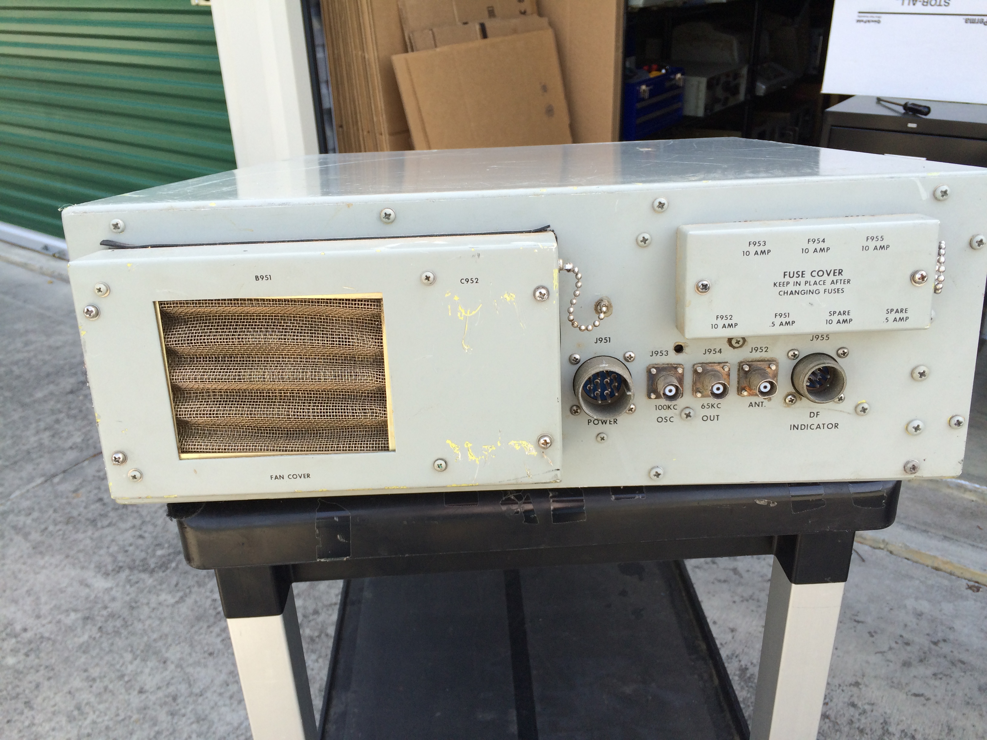
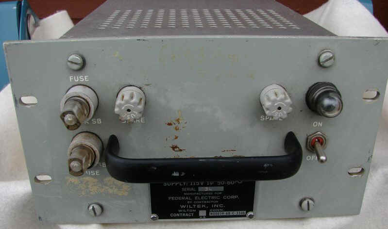
Oscillator- Power Supply O-928/FLR supplies operating power from one to five R-1125/FLR, and includes a 100-kc crystal oscillator which provides a standard reference signal (for incremental tuning) to each receiver. Within the specified frequency range, the R-1125/FLR output is an intermediate frequency band from 35.0 to 95.0 kc which retains all modulation of the received signals with a high degree of fidelity. |
|||
Block Diagram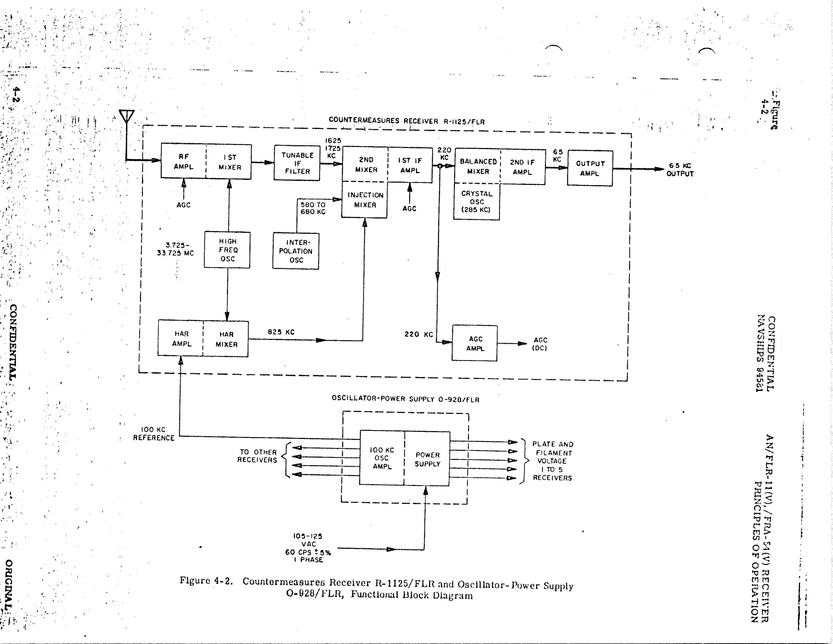 |
Frequency Conversion Diagram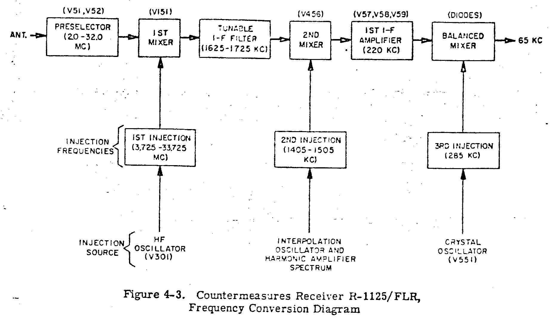 |
Tuning Diagram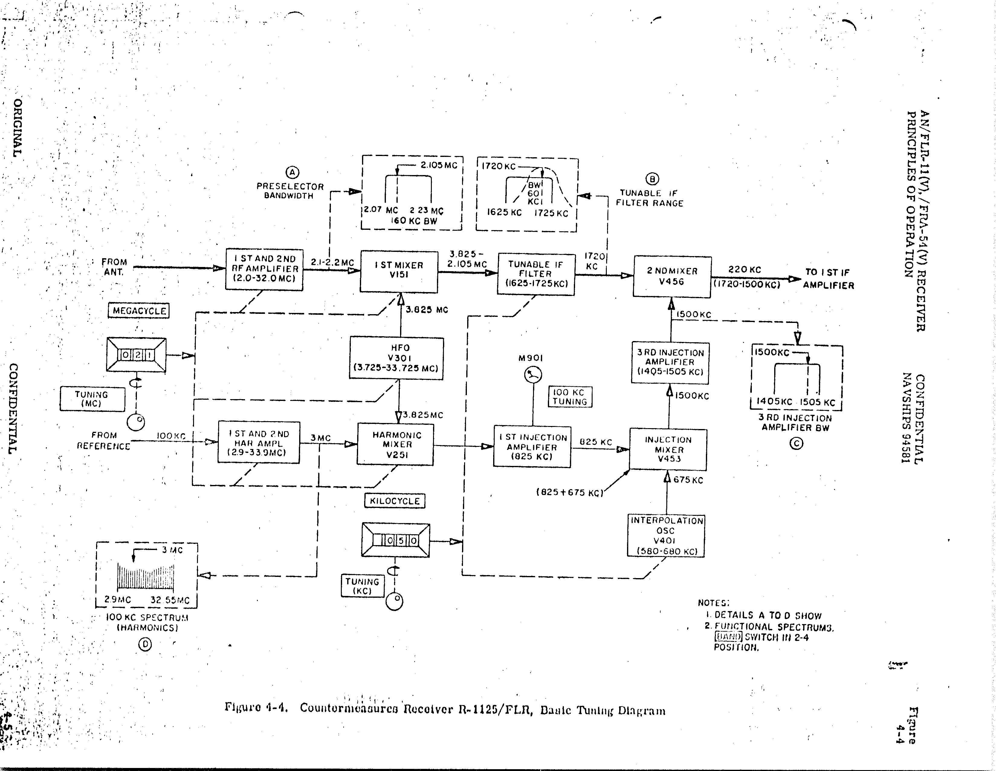 |
-- |
R-1230/FLR with US Navy ID plate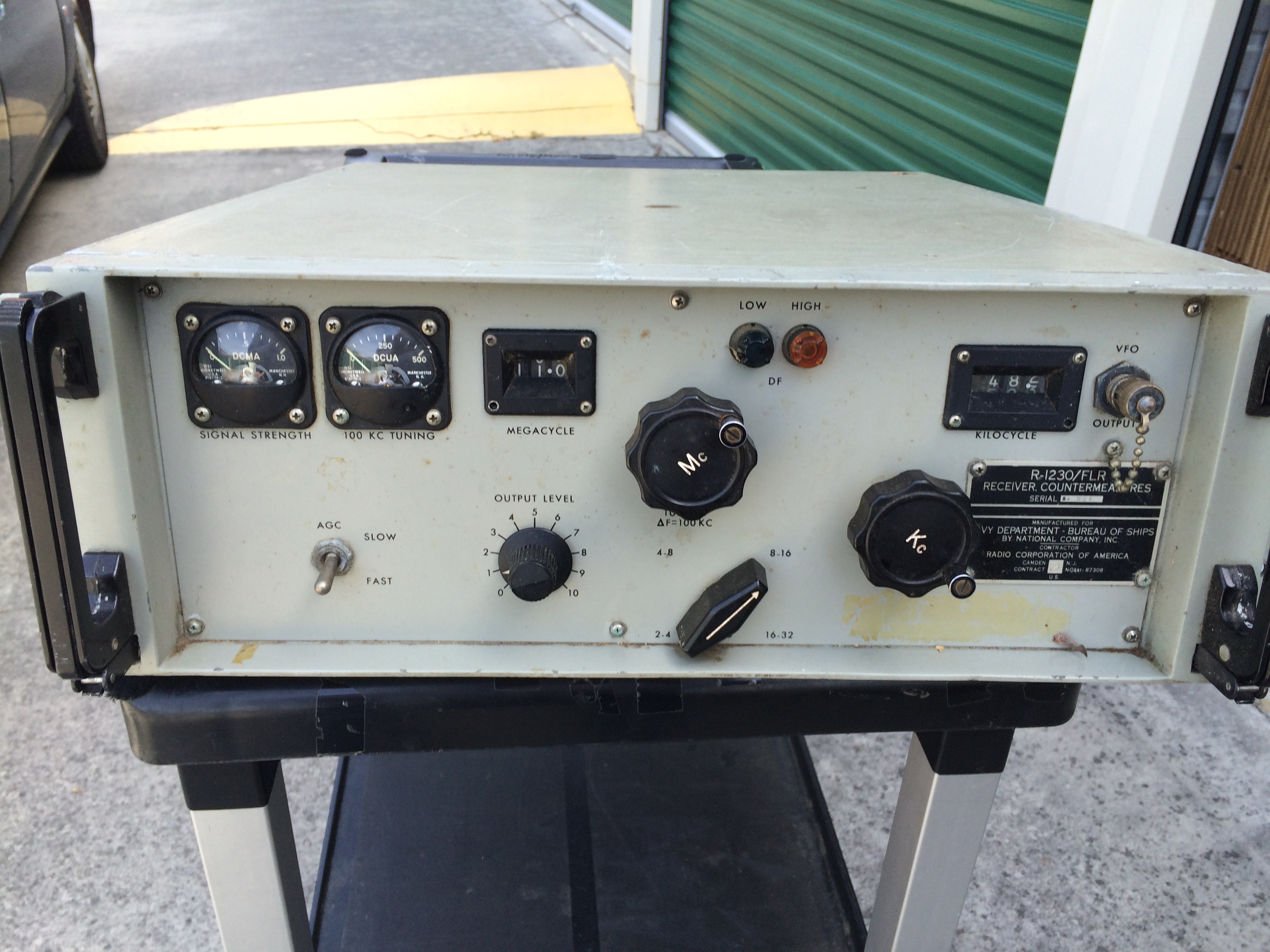 |
 |
 |
 |
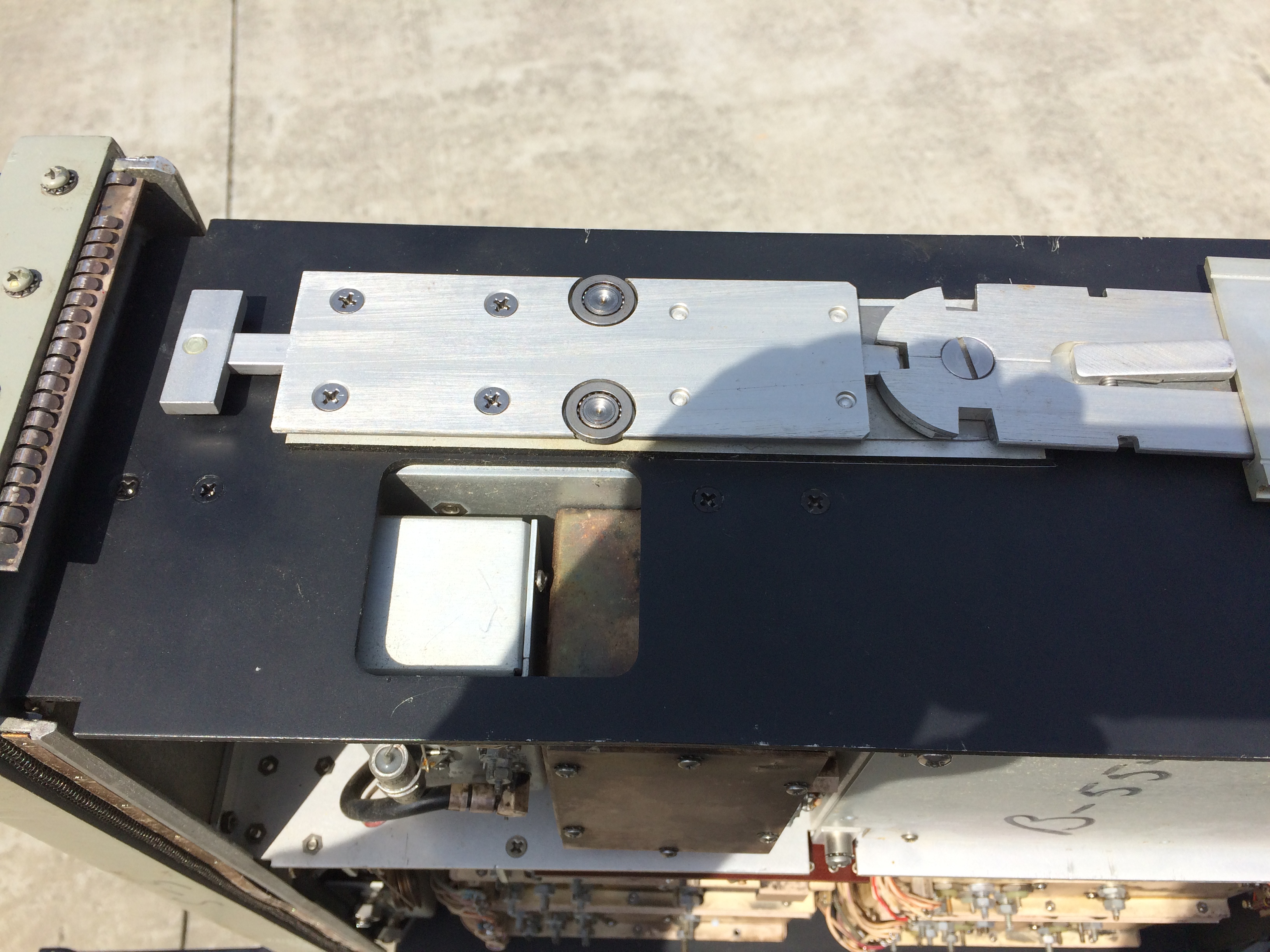
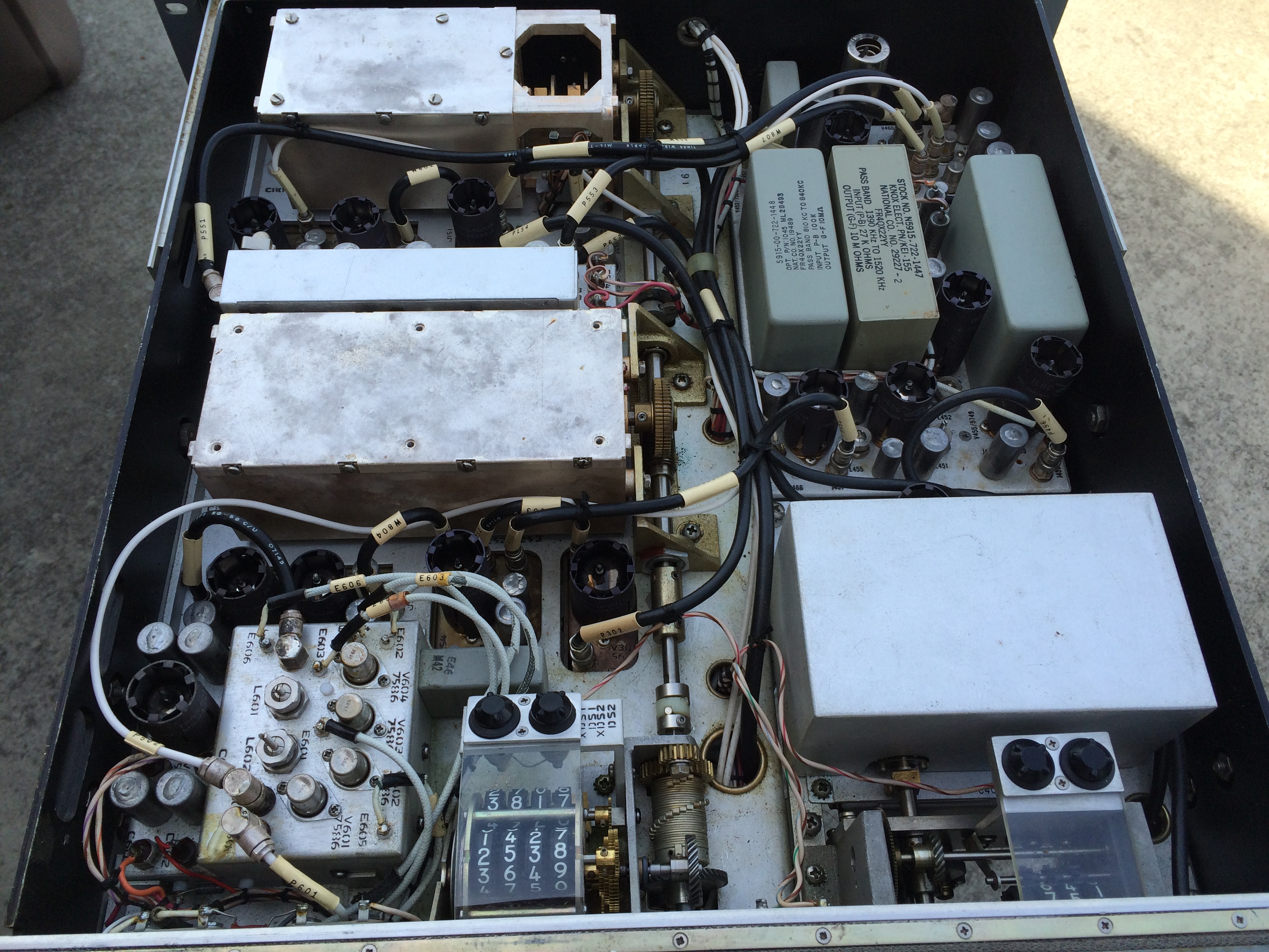
Chassis slides out of the rack-mounted case and also has tilt hinges.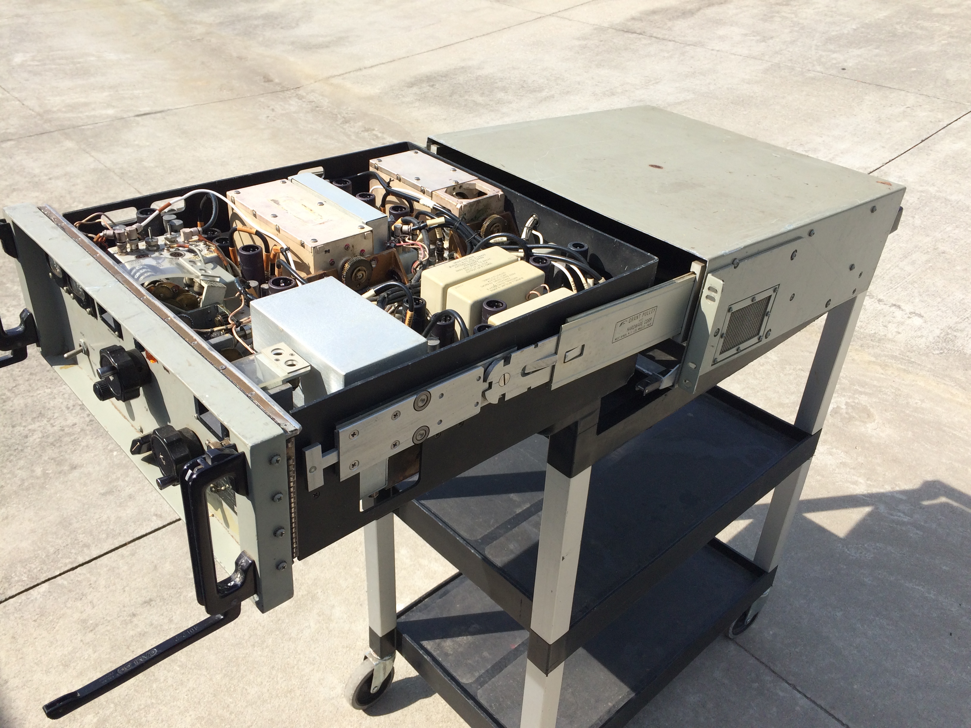 |
 |
 |
 |
R-1230/FLR with Canadian Dept of National Defence ID plate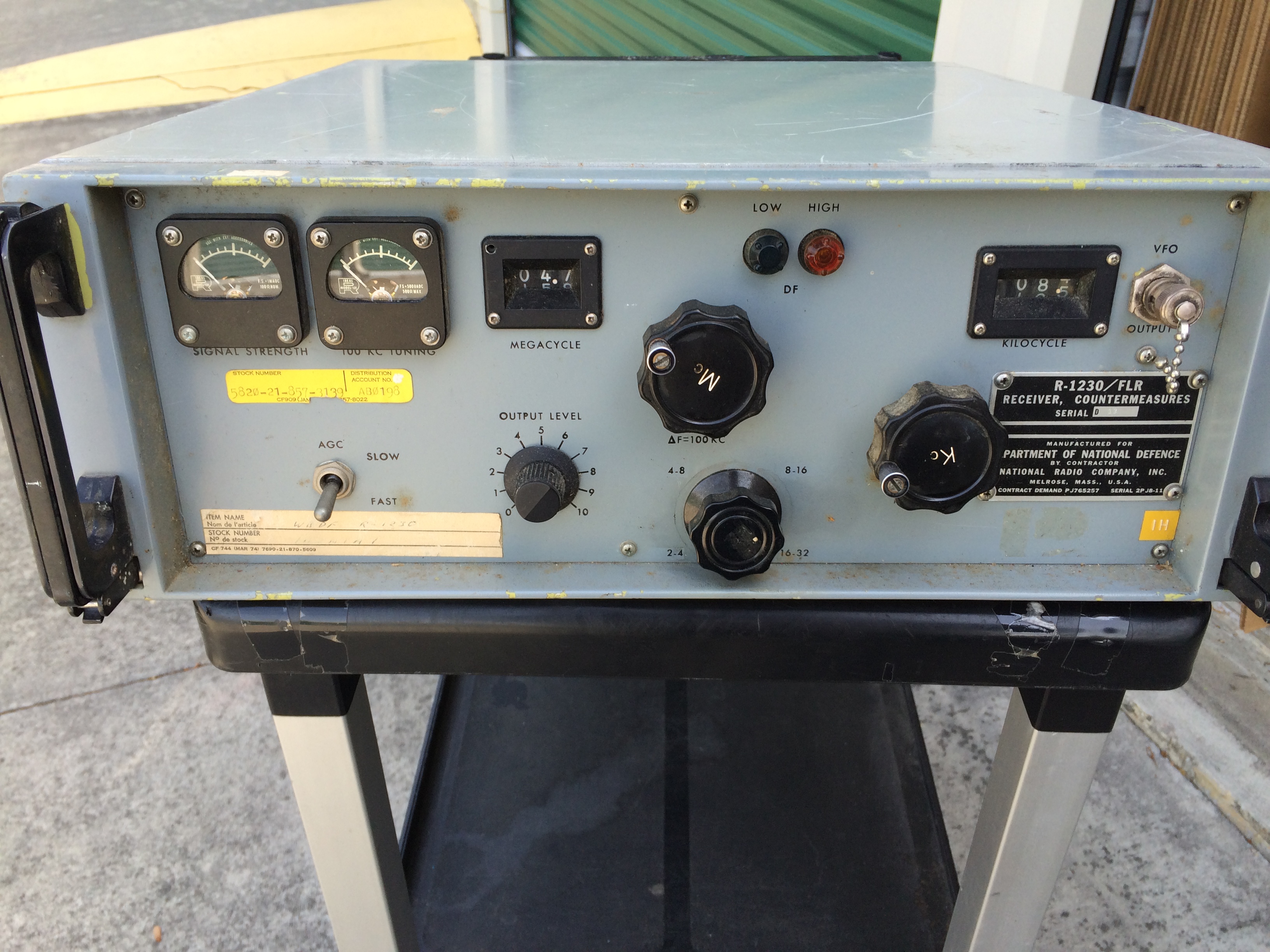 |
 |
 |
 |
|
AN/FRR-68 Receiving Set - need more info - used in GRA-46 and GRA-48
AM-4129/FRR-68 amplifier/detector |
AM-4129/FRR-68 amplifier/detector 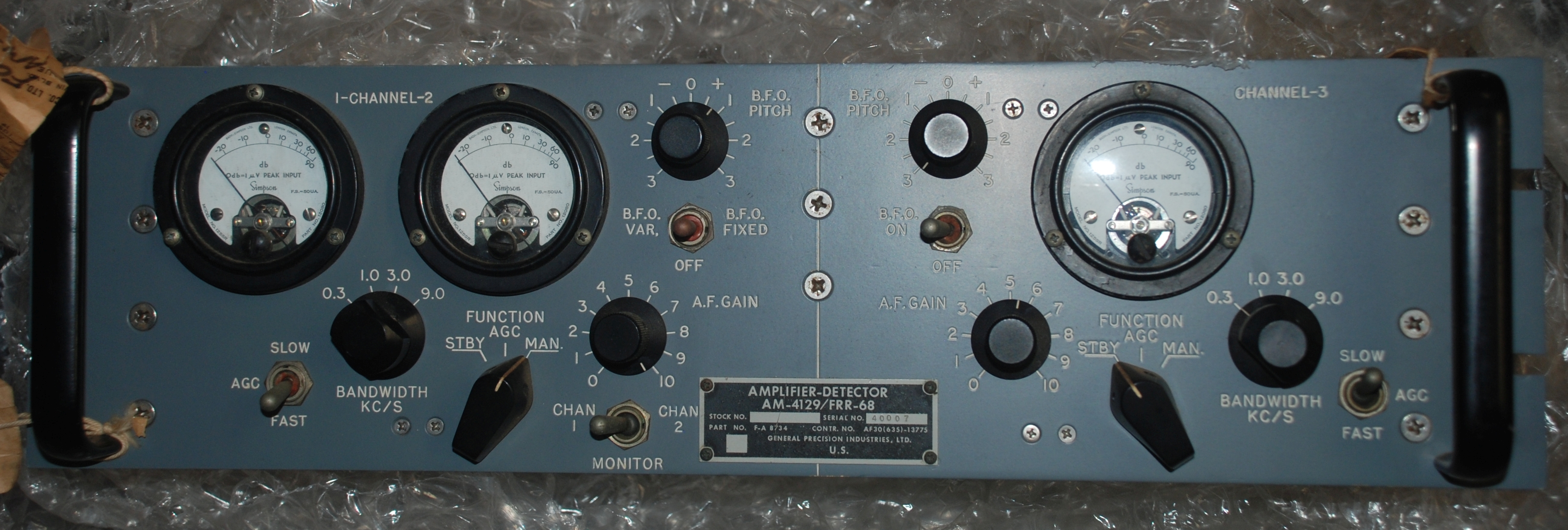 |

|

|
|
"Radio Receiving Set, HF, 1.5-30 MHz. Emission received: A0, A1, A2, A3, A4, A9 in 5 bands. Fixed installation for reception of single RF
signal from three separate antenna inputs. Three independent receiver channels are provided with separate inputs and independent IF outputs. Audio outputs are switched between the various channels. Two of the channels are for optimum phase and amplitude tracking through the freq band. The third channel is for optimum linear phase characteristic throughout the receiver bandpass. 110 vac, 50-60 Hz 1 ph. Manual TO: 31R2-2FRR68." |
|||
|
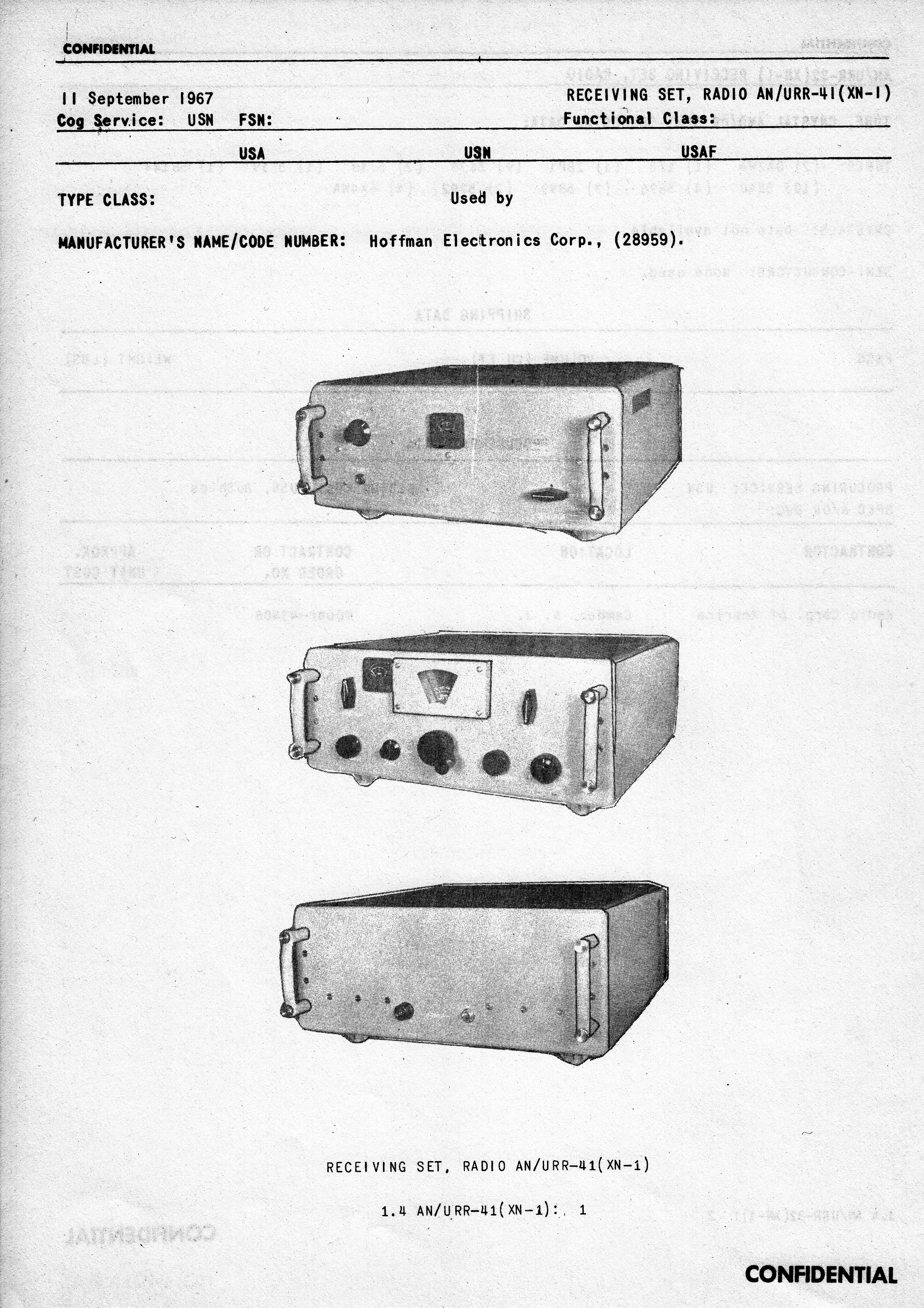
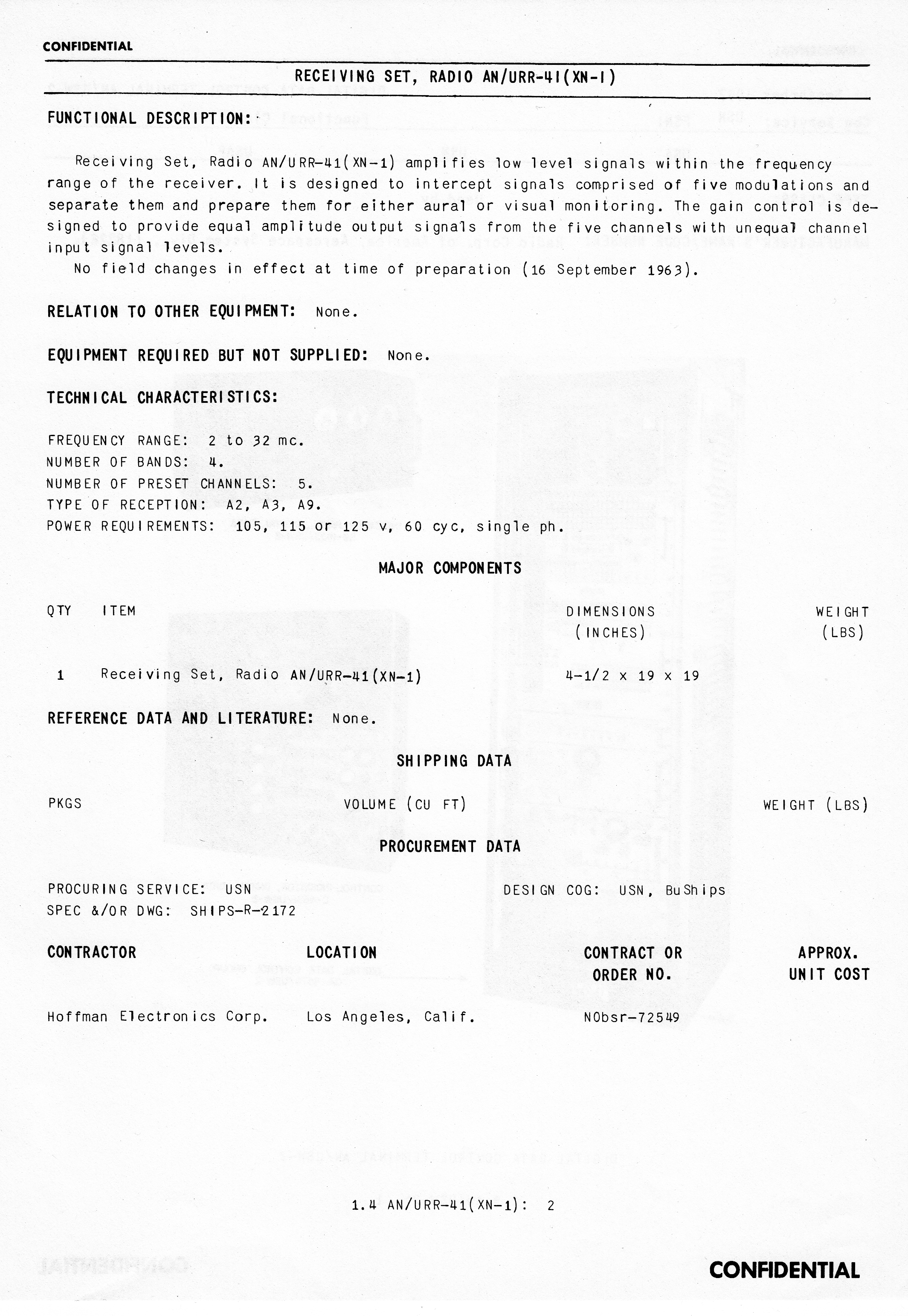
AN/URR-41 Receiving Set AN/URR-41 (XN-1) is designed to intercept signals comprised of five modulations and separate them and prepare them for either aural or visual monitoring. The gain control is designed to provide equal amplitude output signals from the five channels with unequal input signal levels. 2-32 mc, 4 bands, 5 preset channels Manuf by Hoffman please send email if you have any more info |
 |
|
SB-1064/FRR switch for testing URR-41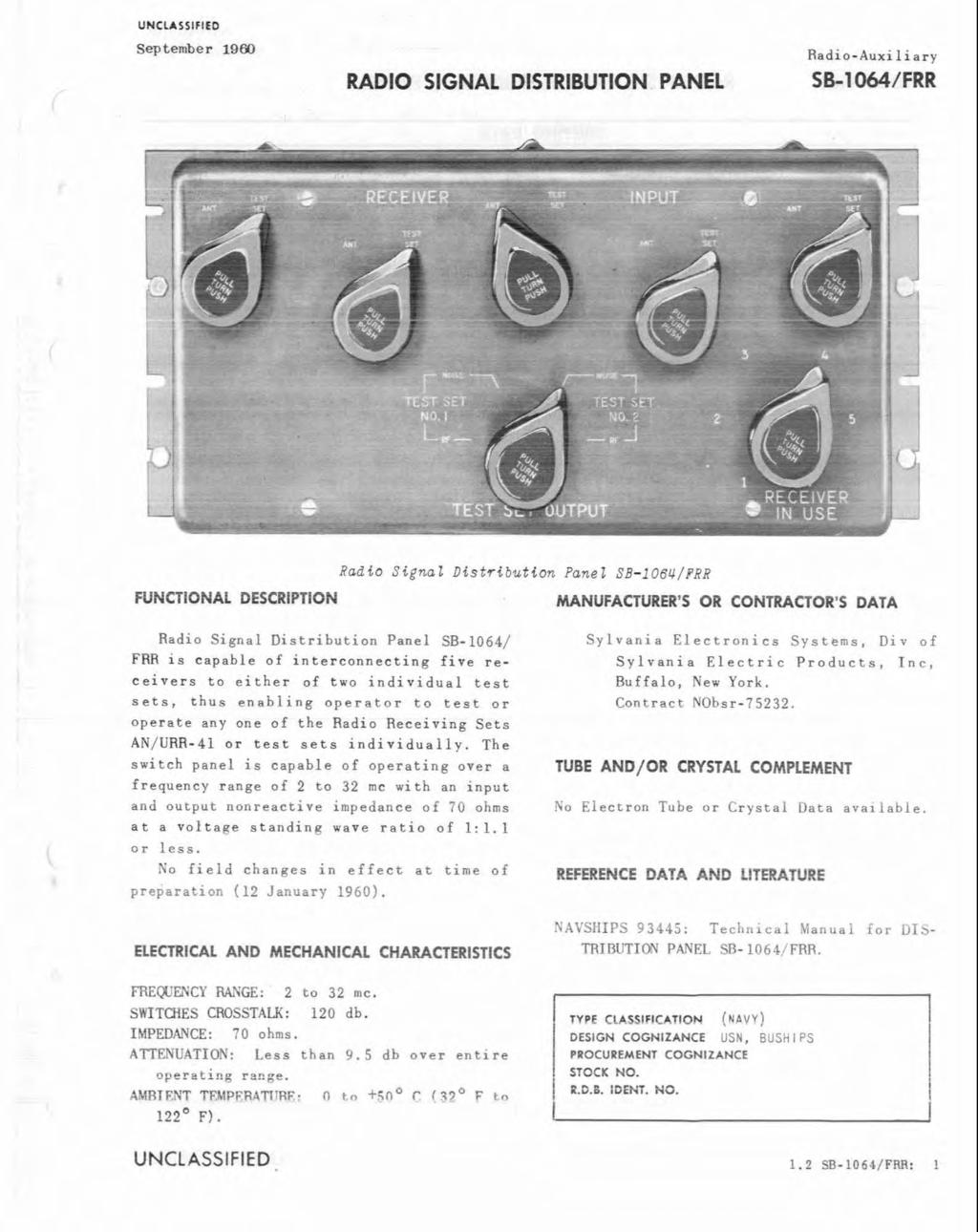
|
Signal Recording Equipment |
|||
|
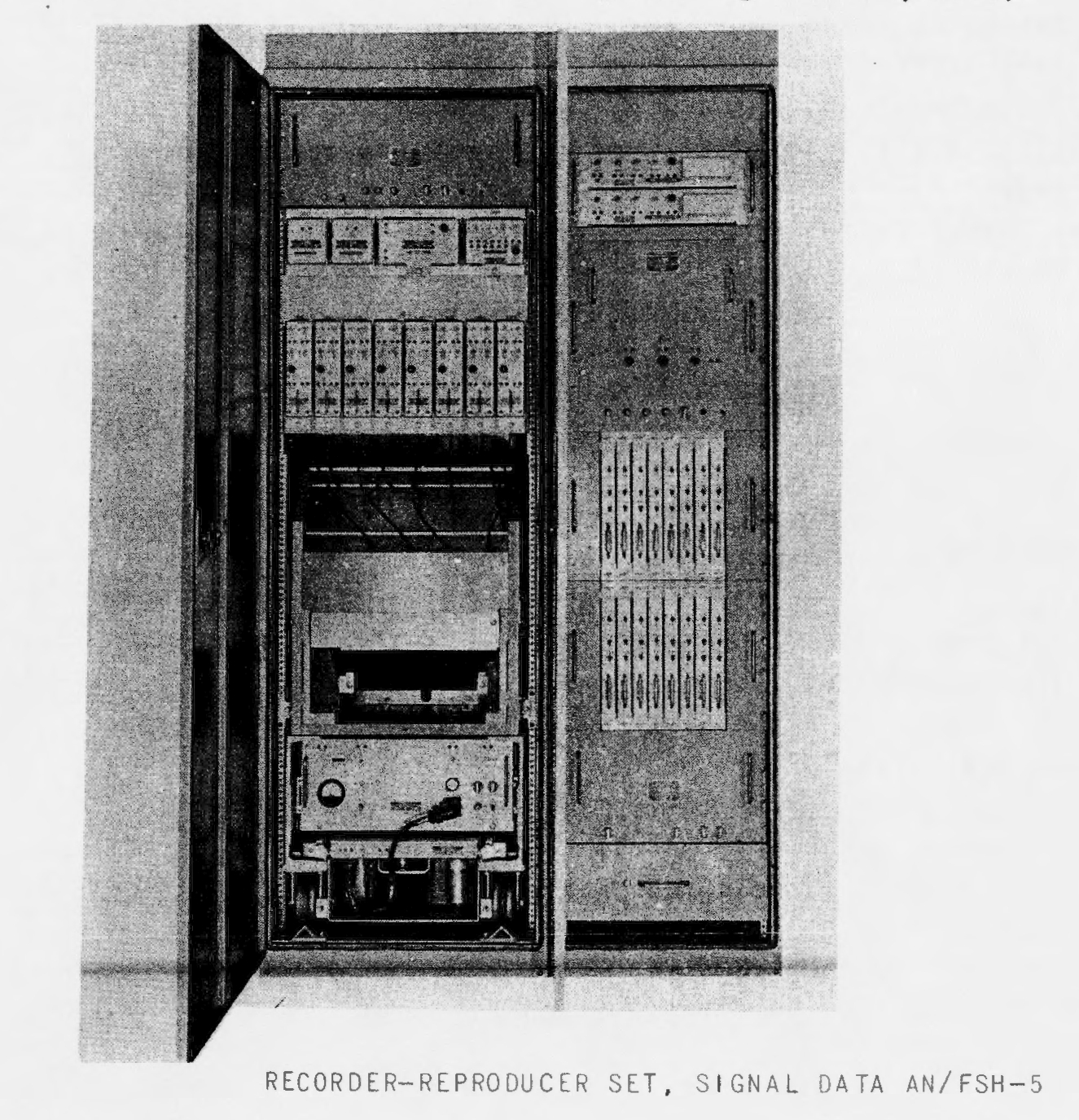
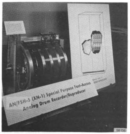
AN/FSH-5 16-channel signal data recorder for pre-detection
recording
AN/FSH-5 spec sheet |
 |
 |
== |
|
RO-133/FRR |
RO-133/FRR Spec Sheet
Manual NAVSHIPS 93449 Manuf by Sylvania Records 2-200 character code groups per second |
Telegraph-Code Tape Recorder RO-133/FRR provides a means of converting the on-off periods of six separate trains of dc pulses (five information pulses trains, one timing reference pulse train) to 10kc envelope type pulses, and recording each on a separate track on a single, narrow, dry-type electro-sensitive paper tape. The equipment contains a tape drive mechanism for moving the tape and electronic circuits to control tape motion and writing. Writing on the tape is accomplished by passing the tape under styli which are fixed in position. Accordingly, the information recorded is in the form of short dashes burned on the upper surface of the tape. | |
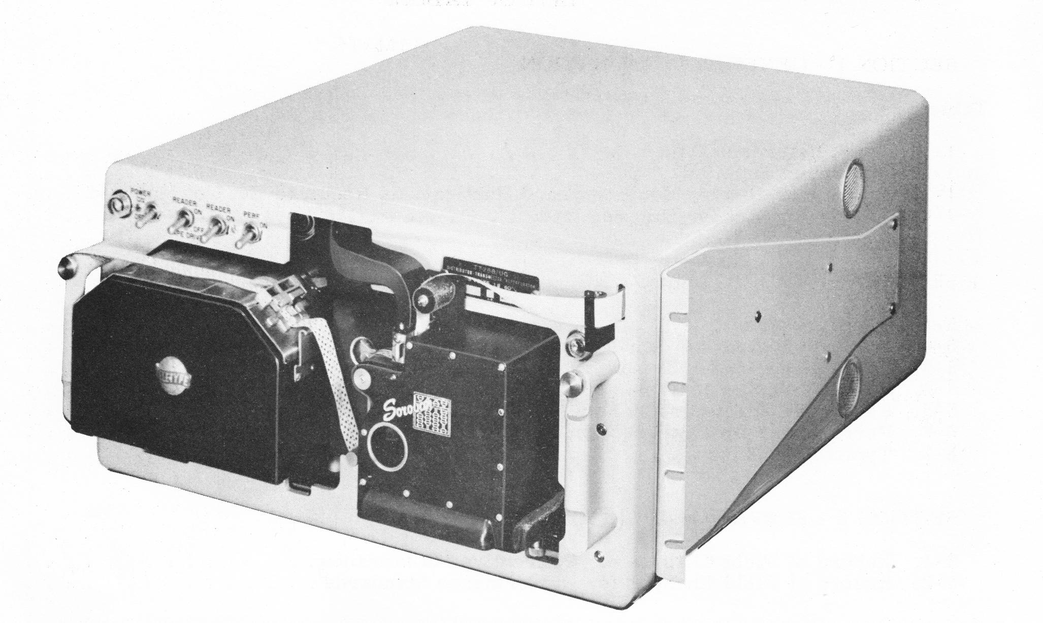
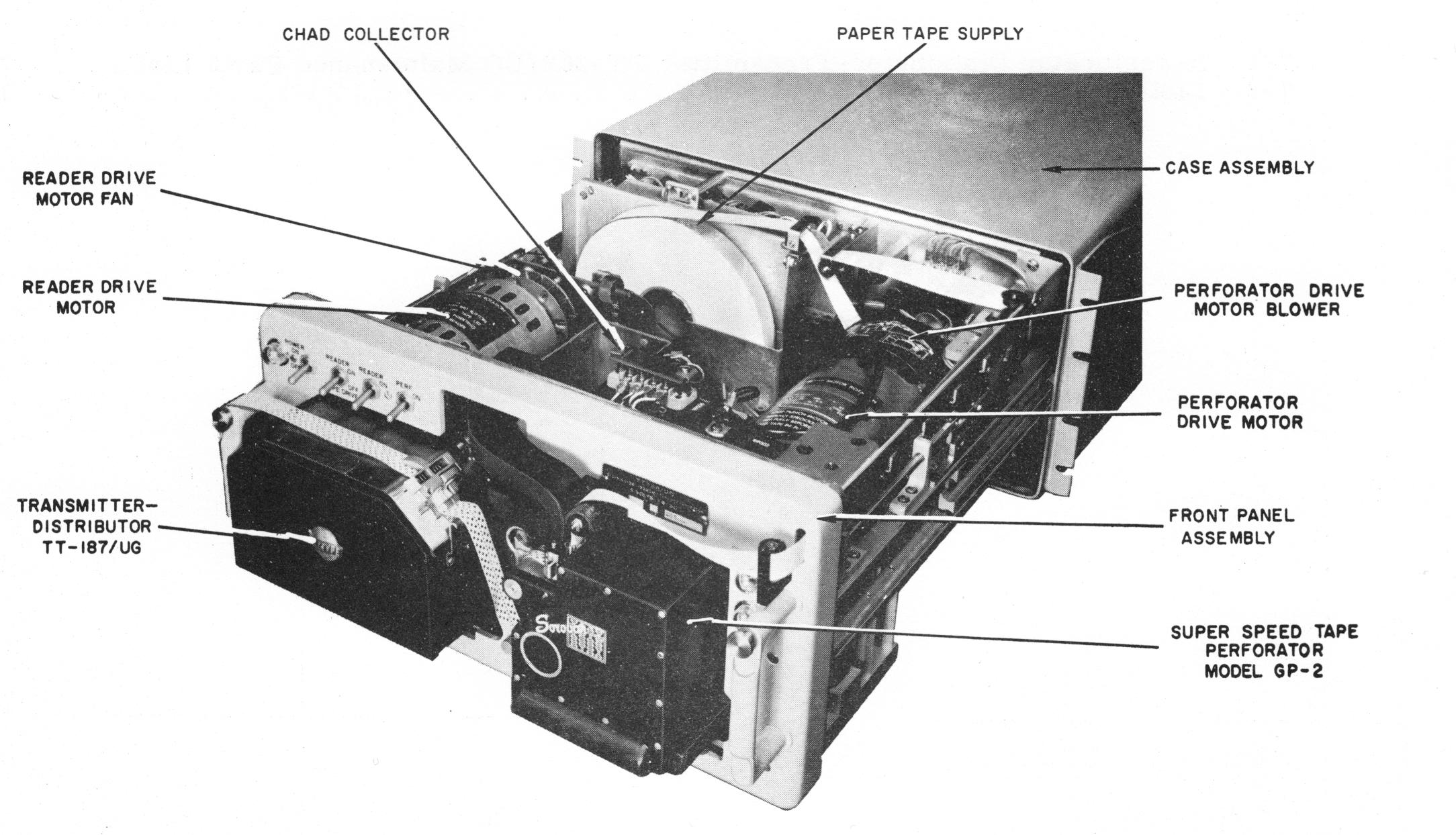
TT-268/UG
|
Super-speed reperf (2400 wpm) + TT-187/UG TD
|
manuf by Sylvania Soroban (reperf) Teletype (TD) Used for RATT intercept |
NAVSHIPS 93454 download 9 MB pdf |
Signal Processing and Display Equipment |
|||
| AM-3637/FR | photo | DC Amplifier | - |
| AM-3645/FRD-10 | photo | Amplifier-Detector | - |
| AM-3647/FRD-10 | photo | RF Amplifier | - |
| AM-3952/FRD-10A | need photo | Goniometer Sine/Cosine Control Amplifier | - |
| C-4503/FR | photo | Indicator Control | - |
| C-4640/FRD-10 | photo | Indicator Control | - |
| C-6071/FRD-10A | need photo | Direction Finder Report Control Group | - |
| CP-762/FRD-10A | need photo | Bearing Digital Counter | - |
Tech report on parasitic oscillations in multicouplers at CDAA sites - thanks to Jim |
|||
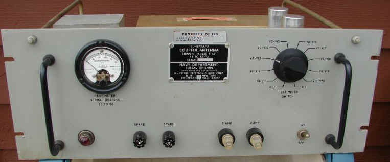
| CU-872/U
used in AN/FRD-10 |
 |
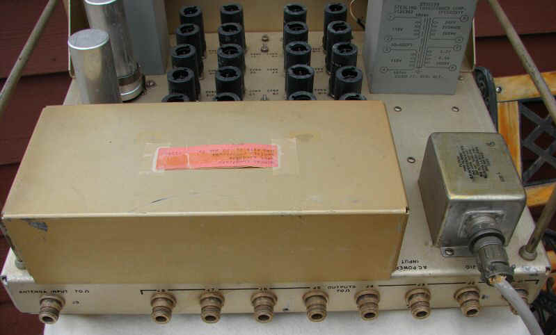 |
2-32mc
8 outputs - tube Diagram and Circuit Description manual avail from Fair Radio |
|
CU-1099/FRR used in AN/FRD-10A |
 |
 |
2-32 mc, 8 outputs - transistor 70 ohm in/out, type BNC connectors Diagram and circuit description NAVSHIPS 94933 - download |
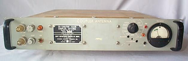
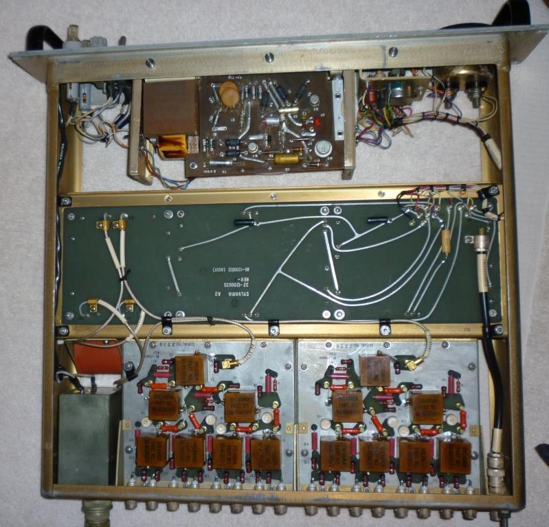
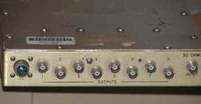
CU-1280/FRD-10A |
|
Multicoupler - 32 output HF for CDAA use
|
manuf Sylvania |
|
|
 |
 |
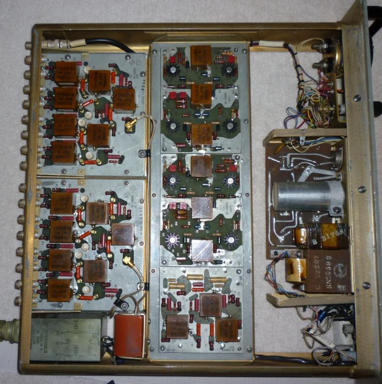 |
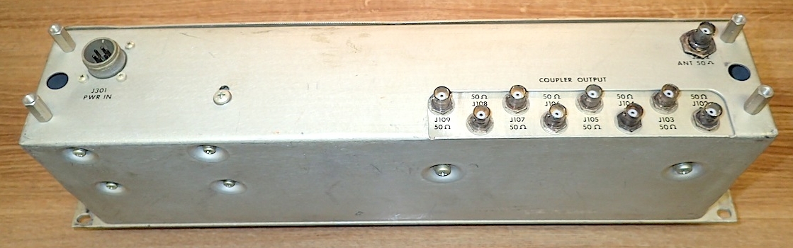
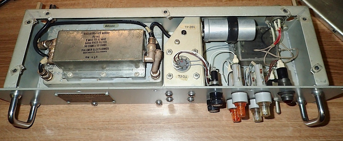
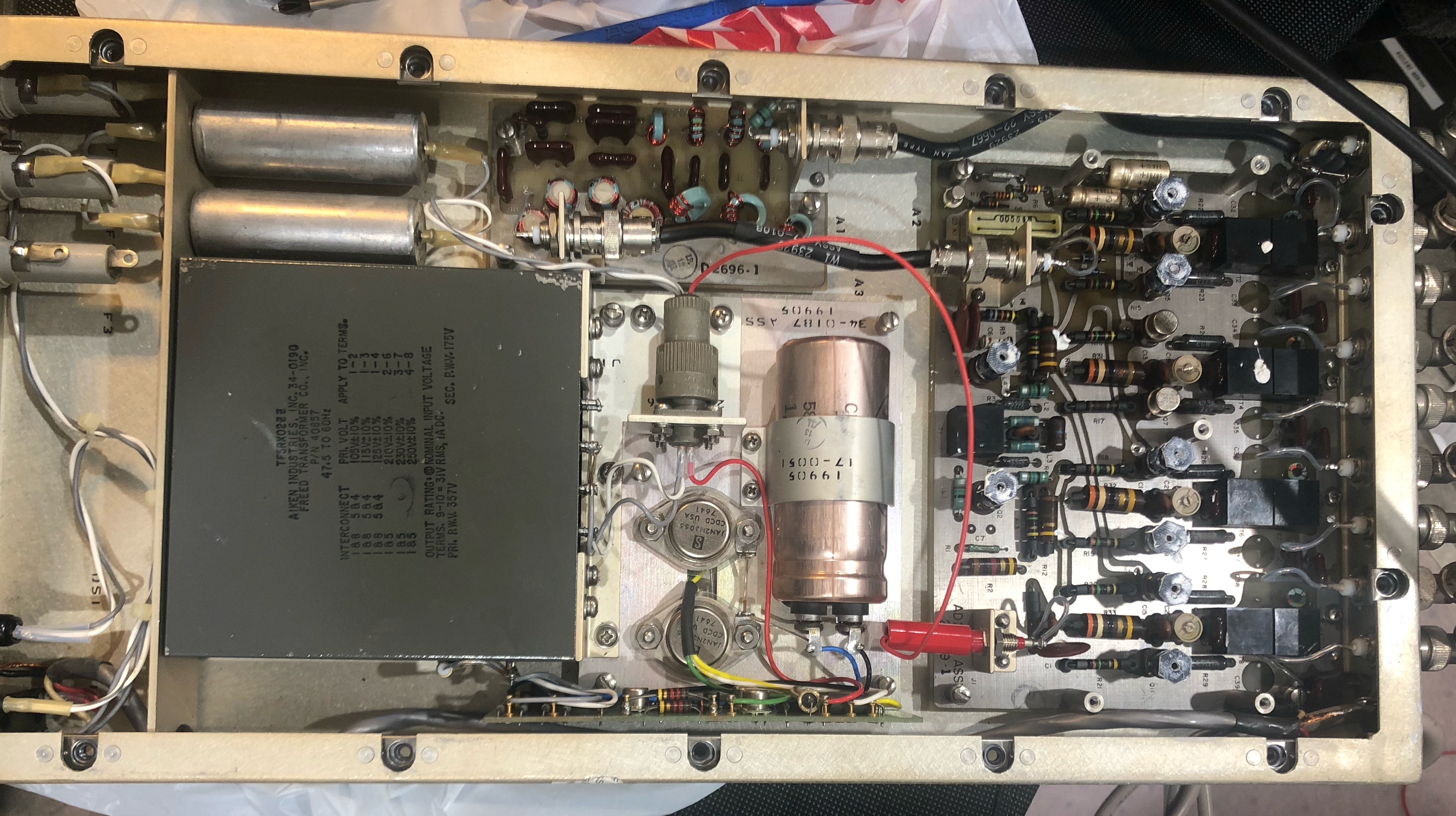
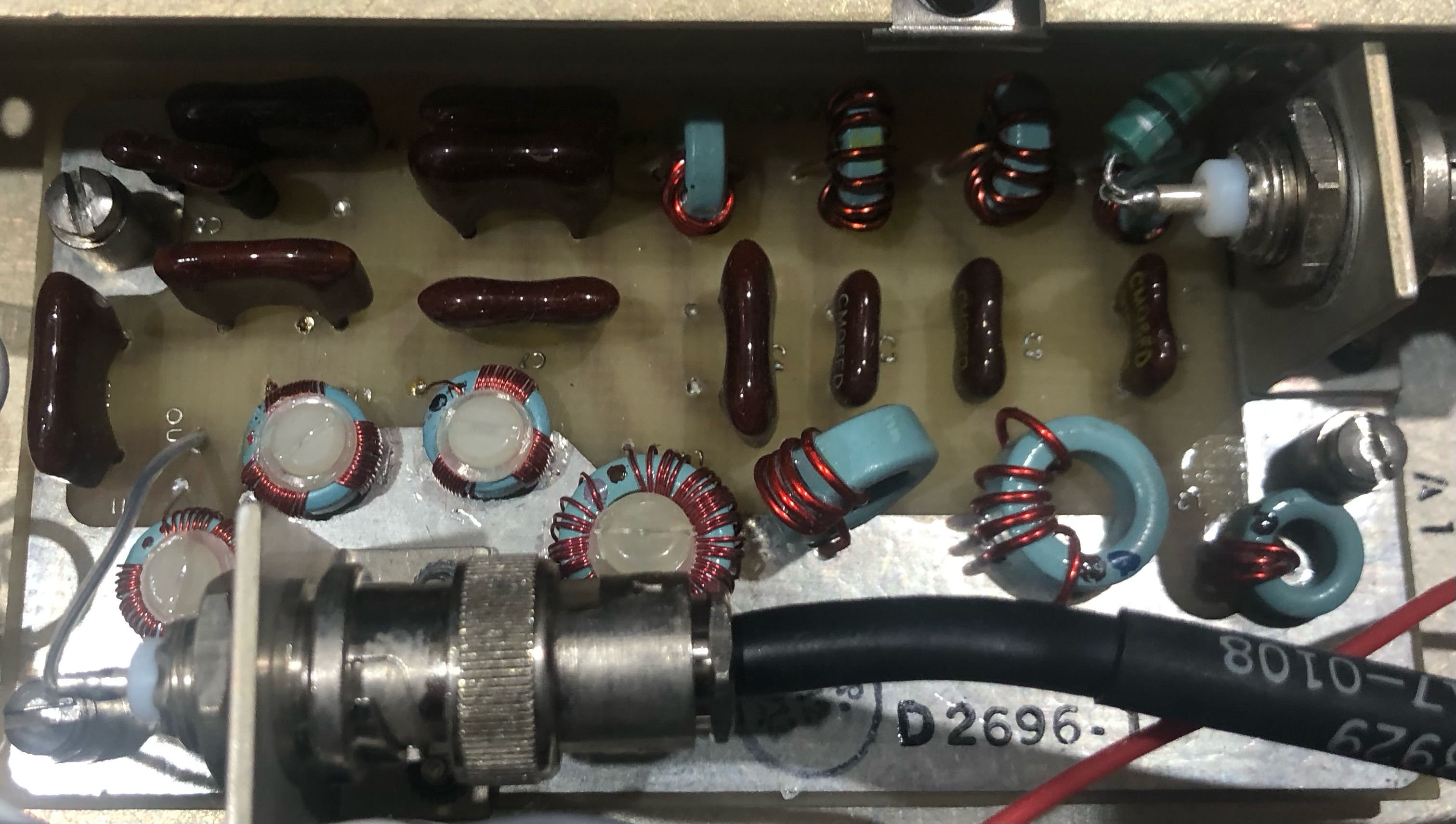
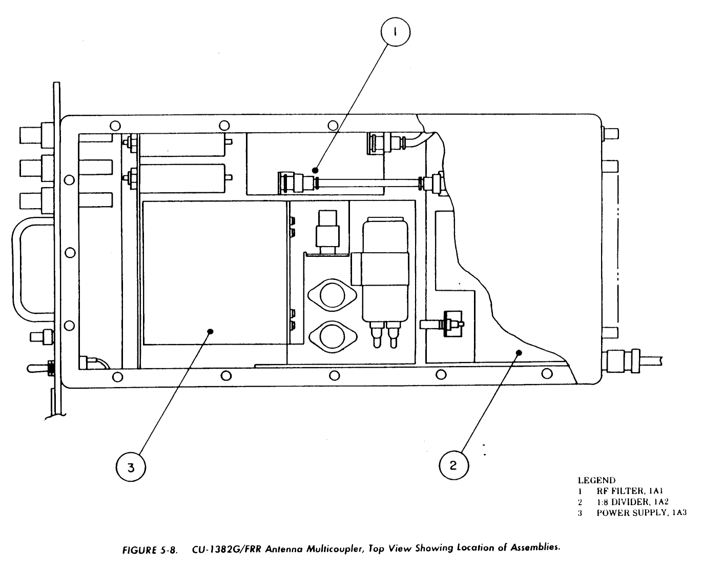
CU-1382/FRR2-32 mc, 8 outputs - transistor thanks to Jim for CU-1382F photos |
CU-1382C/FRR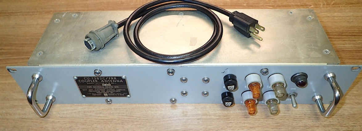 |
 |
 |
CU-1382F/UG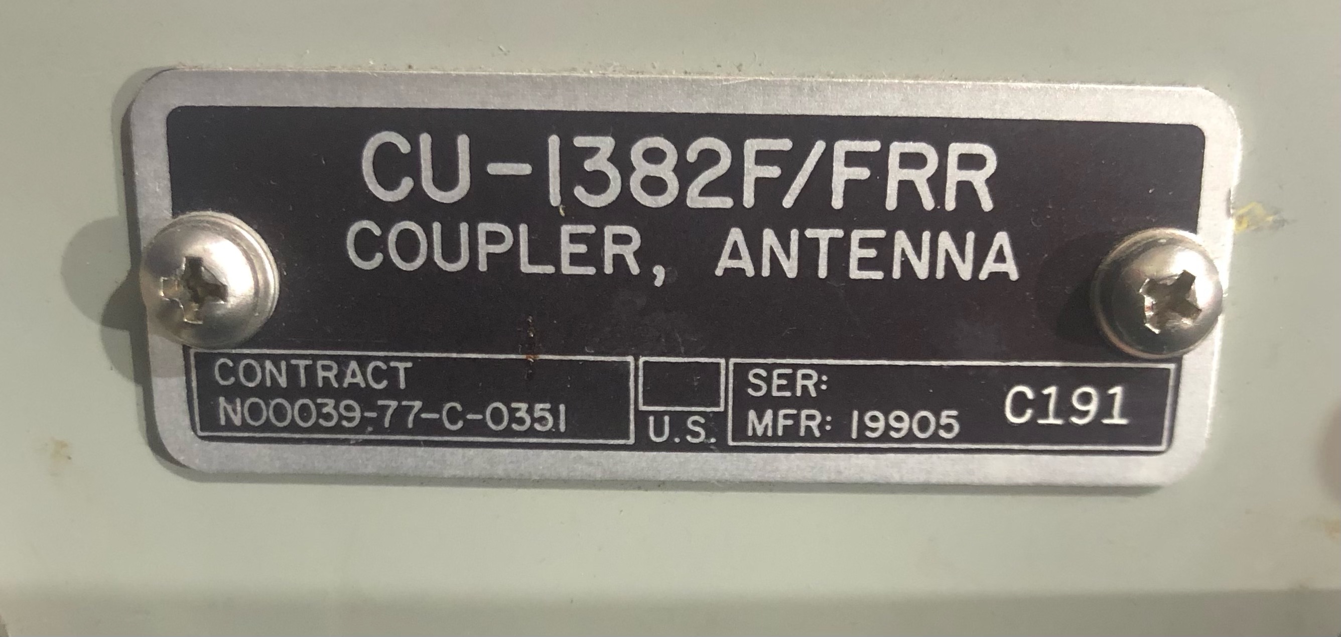 |
 |
 |
|
 |
 |
 |
|
CU-1382G/FRR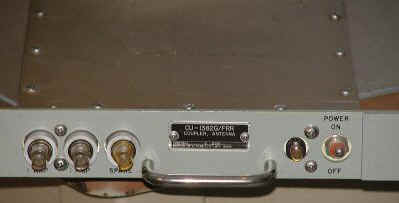 |
 |
 |
|
CU-2282/FRD-10A |
need photo | Omnidirectional Combiner | - |
CU-2289/FRRtwo CU-1382 in one chassis |
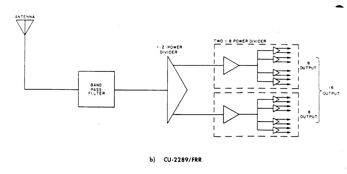
|
|
== |
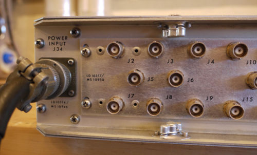
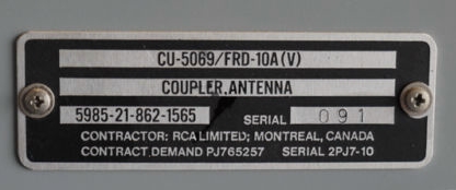
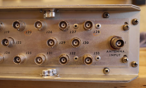
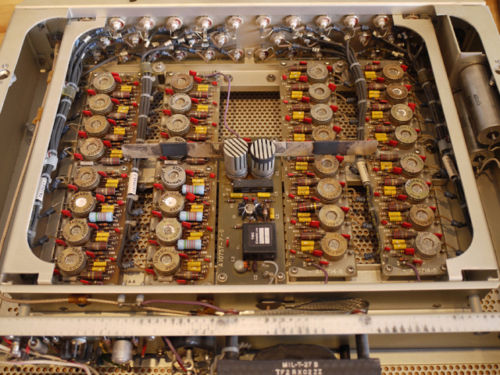
CU-5069/FRD-10A |

|
Multicoupler - 32 output HF for CDAA use
|
manuf by TMC for RCA
article with photos - link
|
| CV-1483/FRD-10 | photo | Wave Form Converter | - |
| CV-1484/FRD-10 | photo | Signal Data Converter | - |
| GO-16/FRD-10(V) | need photo | Goniometer | - |
| GO-17/FRD-10(V) | need photo | Goniometer | - |
| GO-18/FRD-10(V) | need photo | Goniometer | - |
| GO-19/FRD-10(V) | need photo | Goniometer | - |
| GO-34/FRD-10(V) | need photo | Goniometer | - |
| GO-35/FRD-10(V) | need photo | Goniometer | - |
| GO-44/FRD-10(V) | 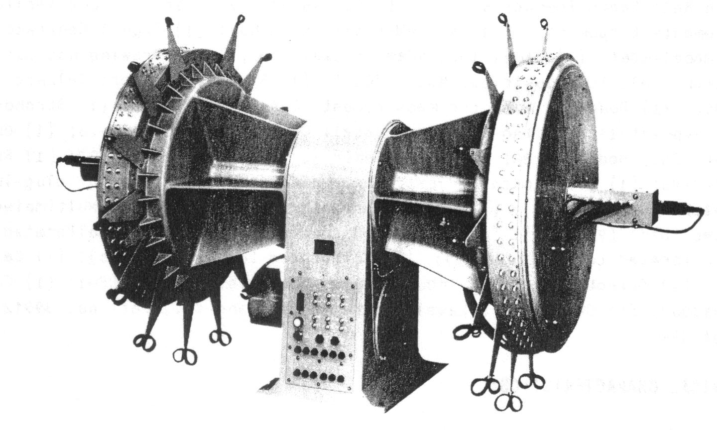 |
Goniometer - 8-32mc 240 inputs, 100 rpm |
- |
| ID-1097/FRD-10 | photo | Digital Display Converter | - |
| ID-1098/FRD-10 | photo | Digital Display Indicator | - |
| ID-1194/FRD-10A | need photo | Digital bearing & Indicator Panel | - |
| IP-693/FRD-10 | photo | Azimuth Indicator | - |
| IP-694/FRD-10 | photo | Azimuth Indicator | - |
| IP-731/FRD-10A | need photo | Azimuth Indicator | - |
| MX-6239/FRD-10A | need photo | Report Logic Unit | - |
| PP-3633/FR | photo | power supply | - |
| PP-3634/FR | photo | power supply | - |
| PP-3650/FRD-10 | photo | power supply | - |
| PP-3949/FRD-10A | need photo | Power supply ? | - |
| PP-3950/FRD-10A | need photo | Power supply -24vdc, +/- 10vdc | manuf General Dynamics |
| PP-3951/FRD-10A | need photo | Power supply +/- 30vdc | manuf General Dynamics |
| RF-160/FRD-10 | photo | RF Detector | - |
| SA-1017/U | photo | RF Transmission Line Switch | - |
| SA-1018/U | photo | RF Transmission Line Switch | - |
| SA-1134/FRD-10A | need photo | Antenna Beam Switching Network | - |
| SA-1135/FRD-10A | need photo | Antenna Beam Switching Network | - |
| SB-2186/FRD-10A | need photo | Patching Panel, Comm | manuf MVP Micro |
| SB-2187/FRD-10A | need photo | Patching Panel, Antenna | - |
| SB-2188/FRD-10A | need photo | Patching Panel, Antenna | - |
| SB-2202/FRD-10A | need photo | Patching Panel, Comm | manuf MVP Micro |
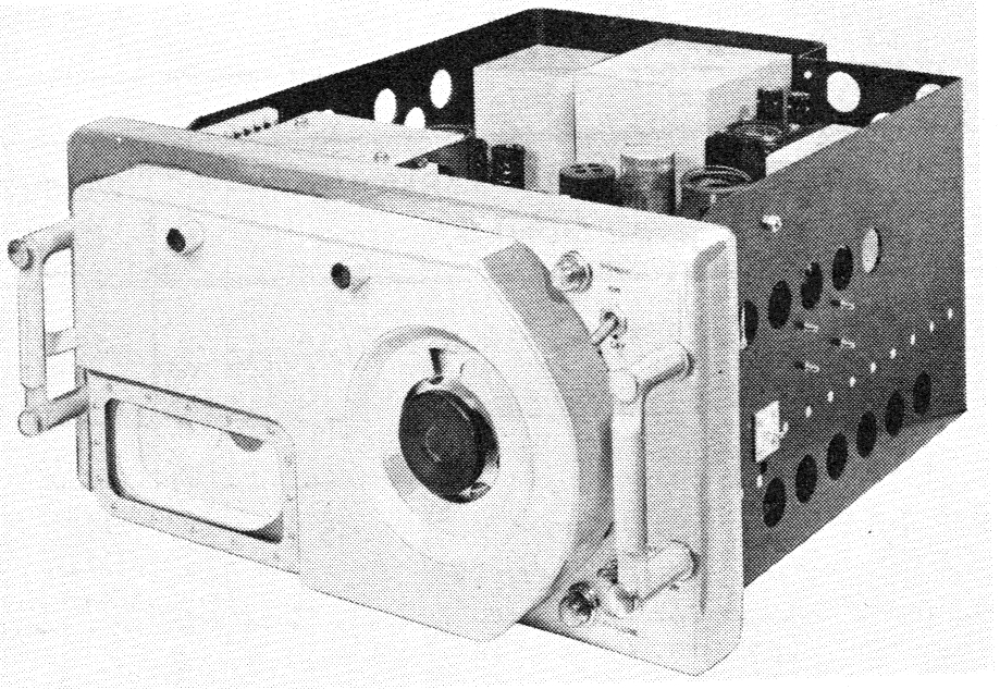
| AN/USM-109 | 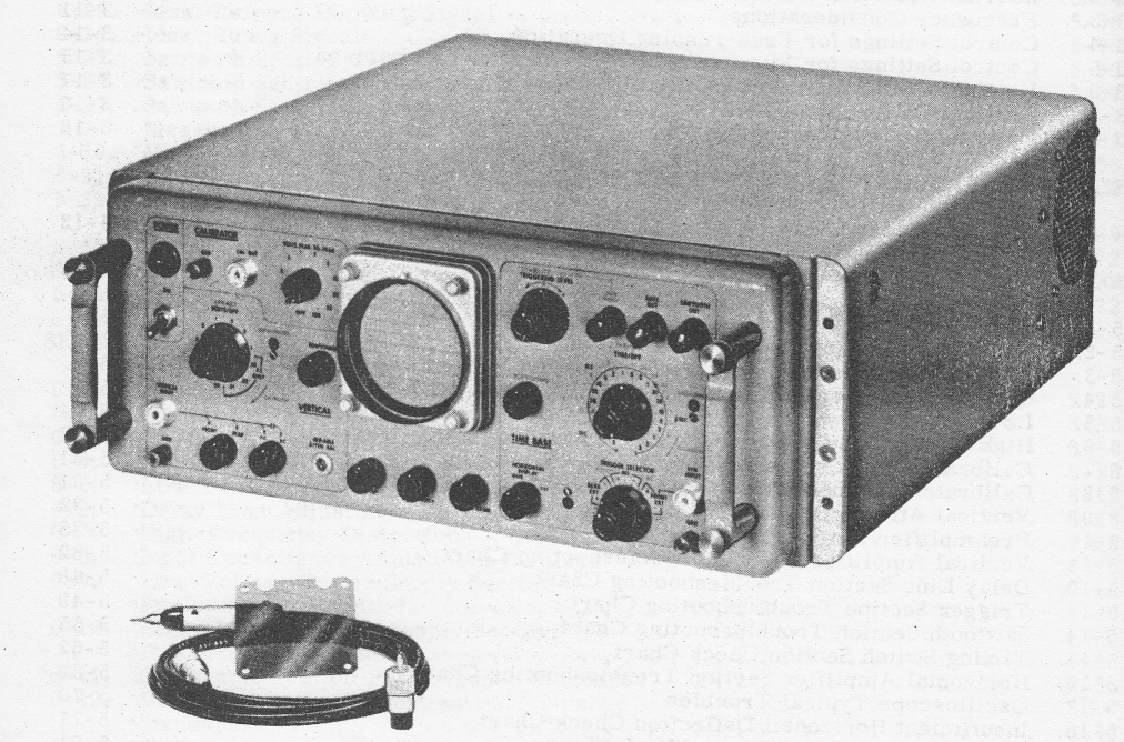 |
Oscilloscope - modified Tektronix RS16 | Sylvania contract |
References


