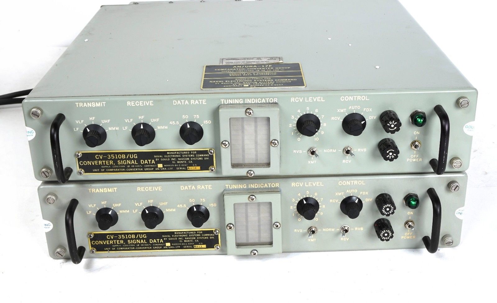
AN/URA-17F diversity system is composed of two CV-3510B/UG
AN/URA-17G diversity system is composed of two CV-3510C/UG
Note: AN/URA-17, -17A, -17B, -17C, -17D are receiving converter systems only, using CV-483/URA-17
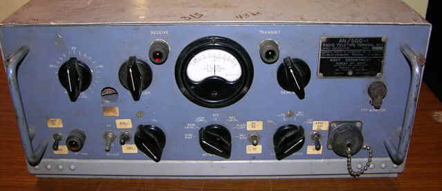
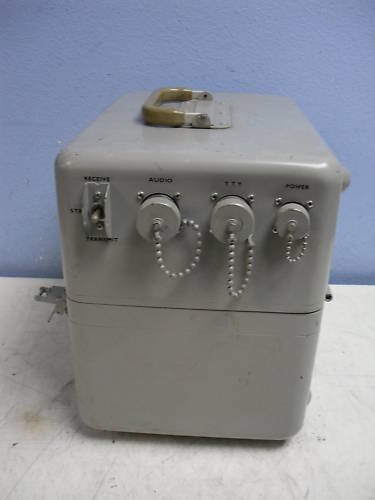
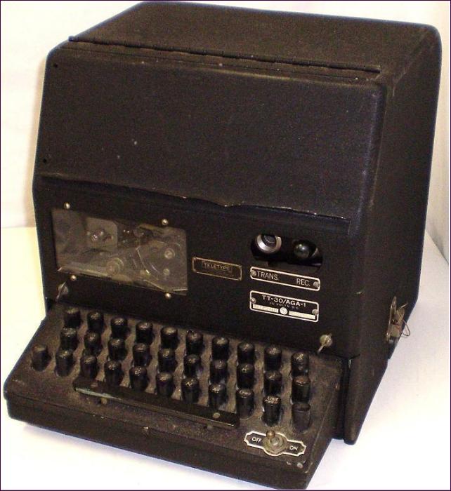
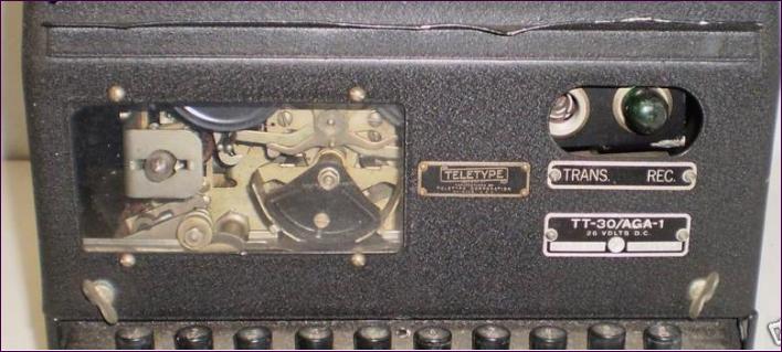
AN/SGC-1, AN/SGC-1A
(TT-40/SGC-1, TT-40A/SGC-1)
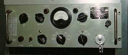
AN/SGC-1
AN/SGC-1 modified for ham use

AN/SGC-1A (modified from -1?)
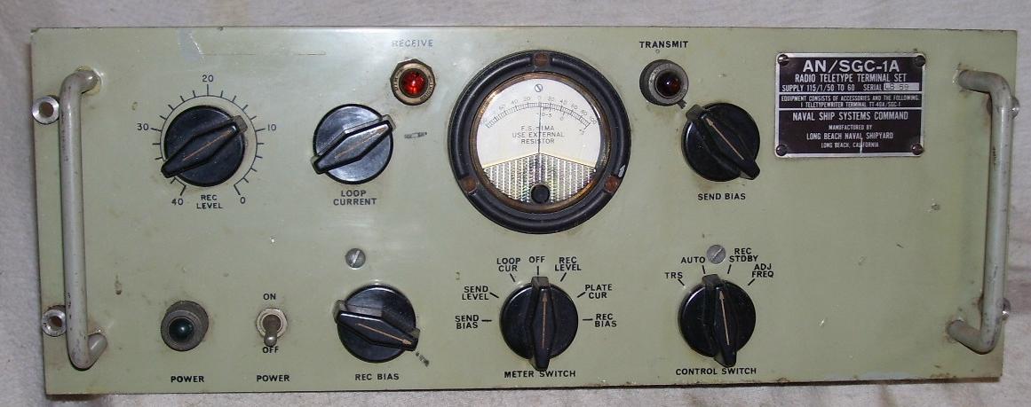
Later AN/SGC-1A
NAVSHIPS 91152 (SGC-1)
NAVSHIPS 91503 (SGC-1A) - available from WA5CAB
See CQ magazine April 1970, page 82, for info (avail at http://hamcall.net/cq)
manuf - Remler
CV-2460/SGC
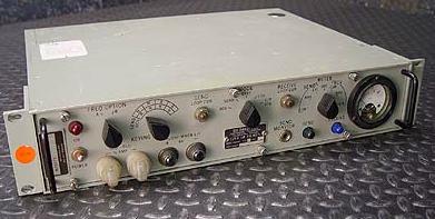
(converter and keyer)
A = 500Hz space / 700Hz mark (UHF)
B = 1575Hz space / 2425Hz mark (HF)
Note: these are reverse polarity to CV-3510 below
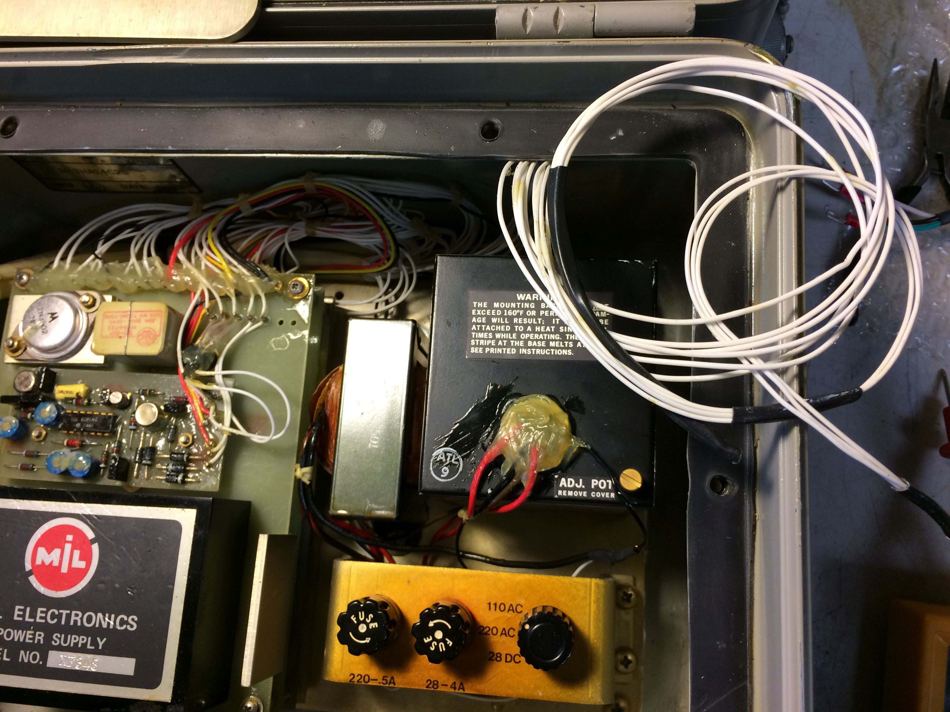
manual NAVELEX EE162-AB-MMO-010/E110
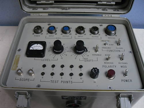
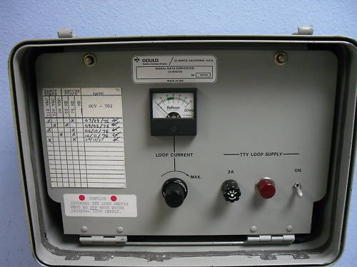
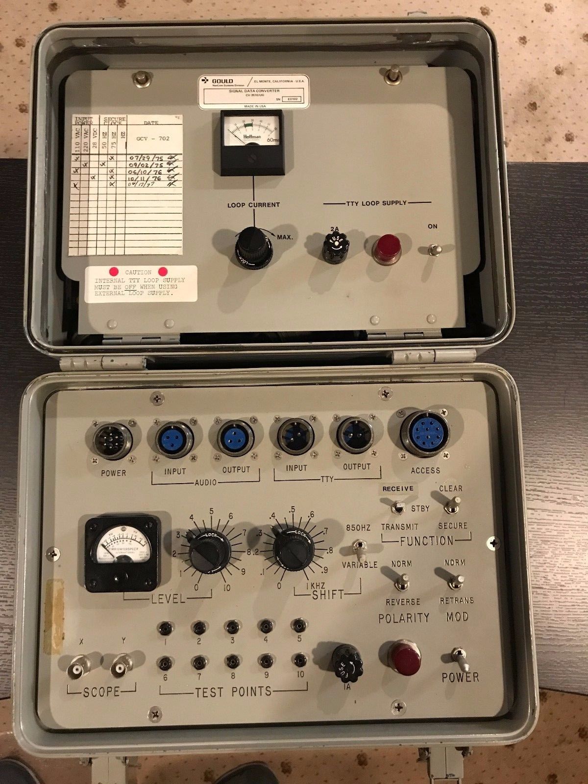
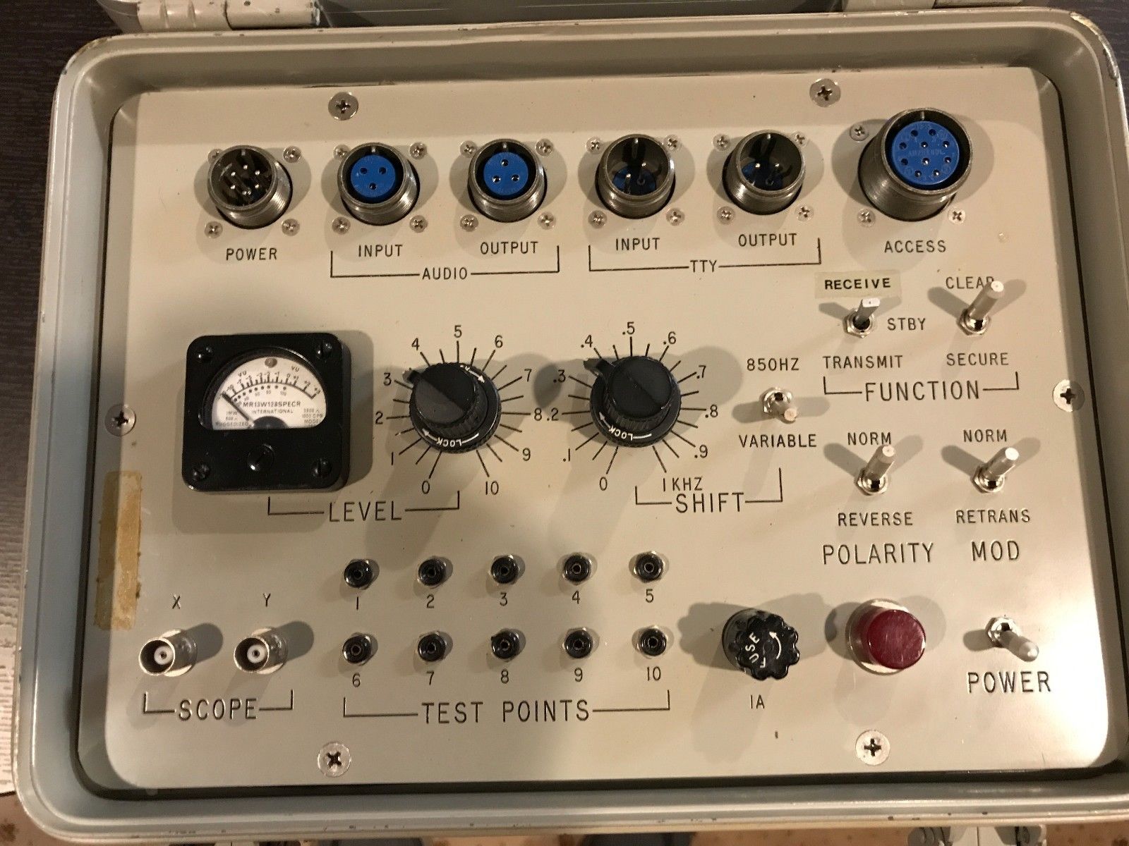
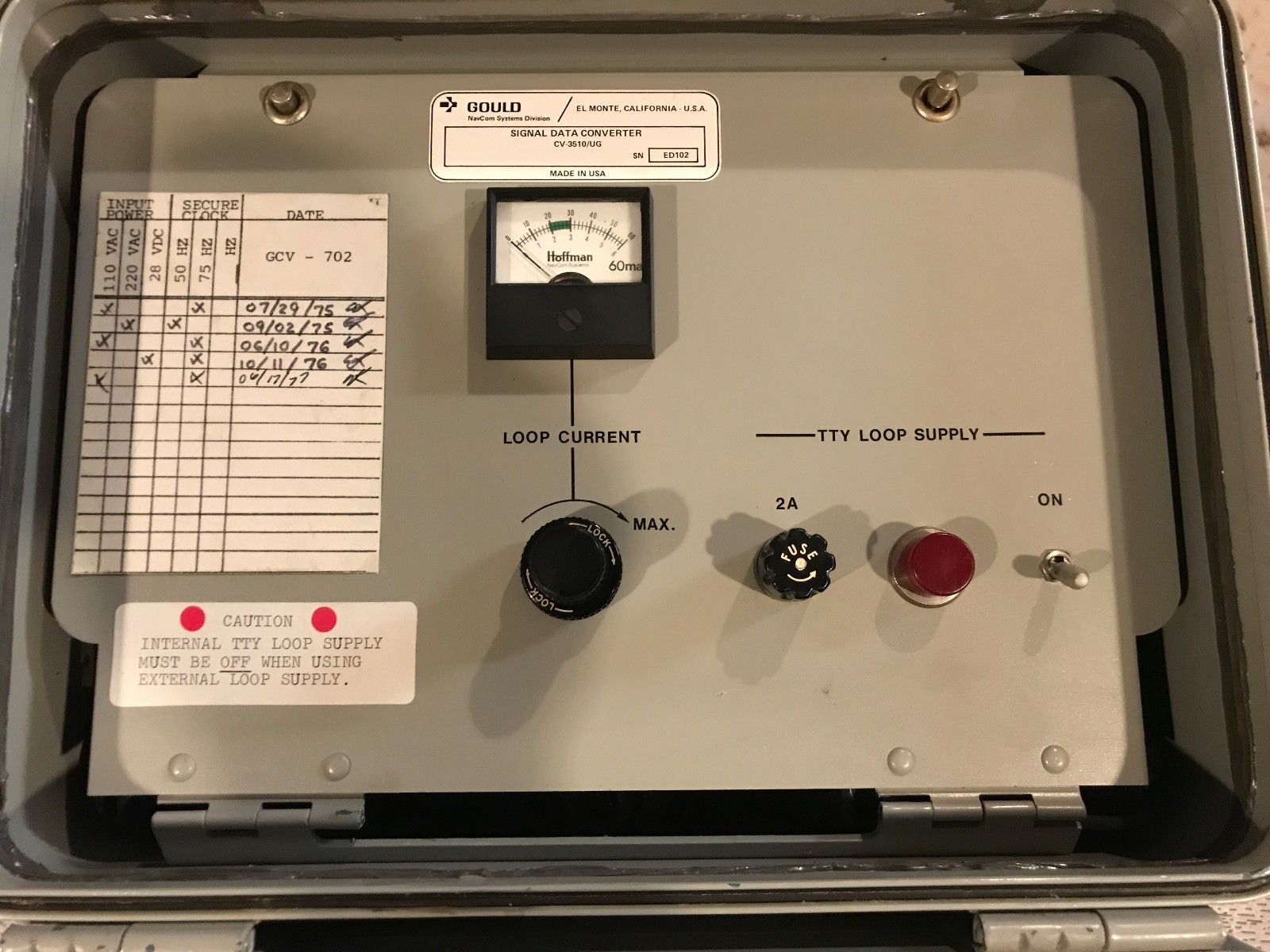
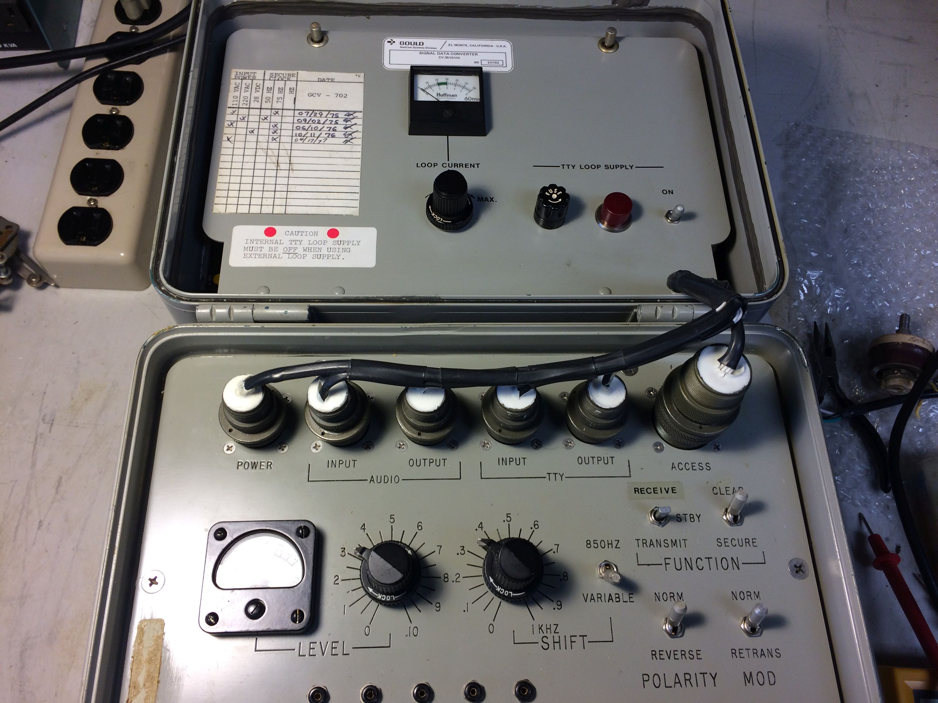
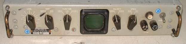
CV-3510/UG Signal Data Converter
TM 11-5895-1370-12-3
Looks like it can operate on 220 or 110vac (400Hz), or 28vdc

CV-3510A/UG
(part of AN/URA-17E)

AN/URA-17E diversity system comprises two CV-3510A
(converter and keyer)
VLF= 1000 Hz mark / 1050Hz space
LF= 915Hz mark / 1085Hz space
HF= 1575Hz mark / 2425Hz space
UHF= 500Hz mark / 700Hz space
MMM= 1615Hz mark / 1785Hz space
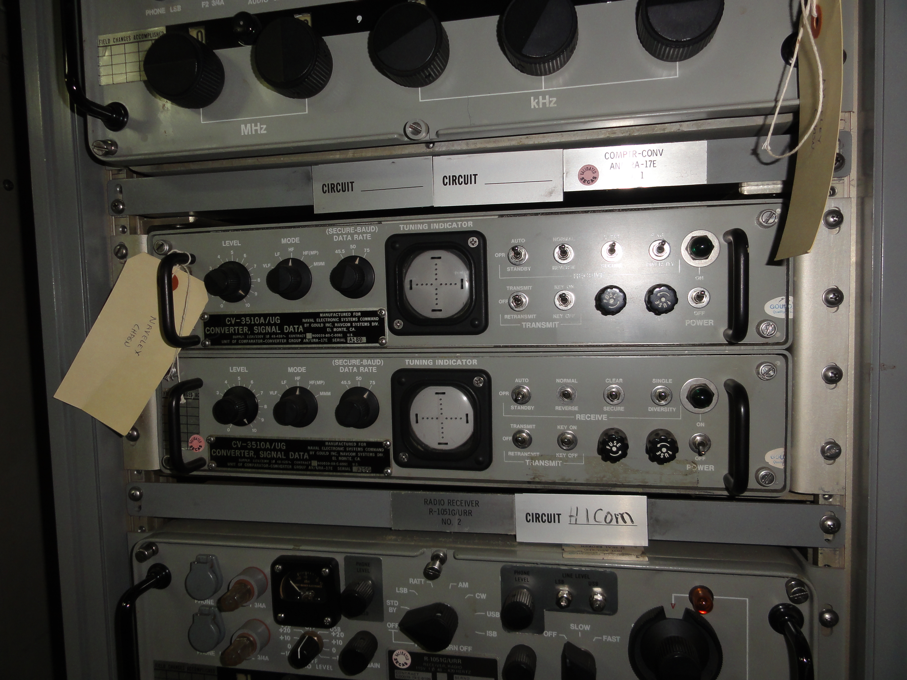
Manuf Gould Navcom
Manual is EE162-AH-OMI-010/E110 URA17E - manual
URA-17E specs
URA-17E connections
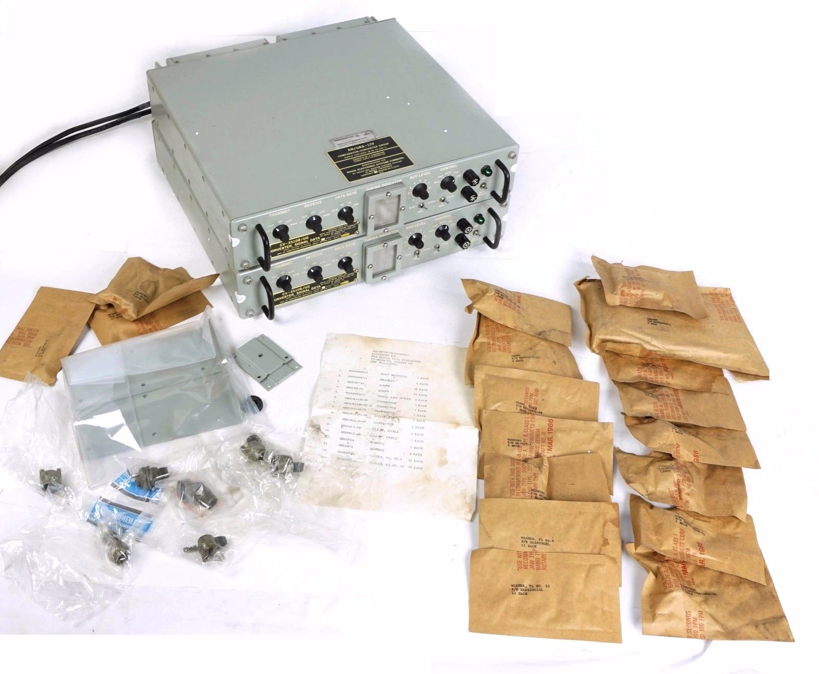
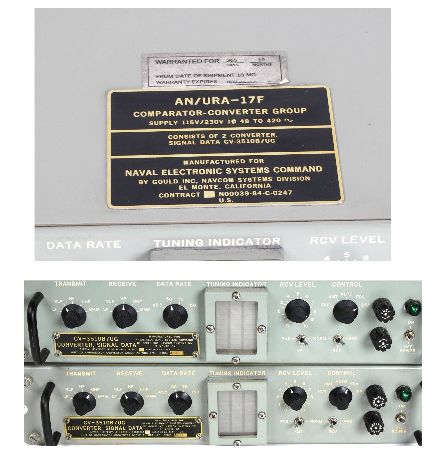
CV-3510B/UG
(part of AN/URA-17F)
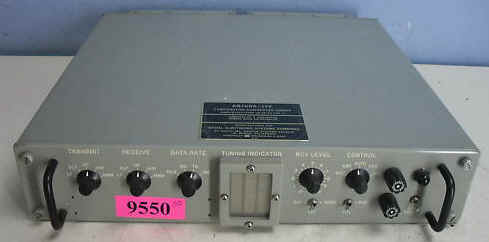

(converter and keyer)
VLF= 1000 Hz mark / 1050Hz space
LF= 915Hz mark / 1085Hz space
HF= 1575Hz mark / 2425Hz space
UHF= 500Hz mark / 700Hz space
MMM= 1615Hz mark / 1785Hz space
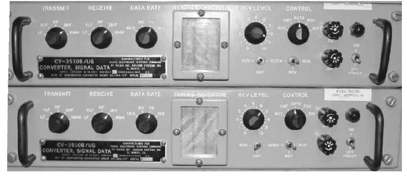
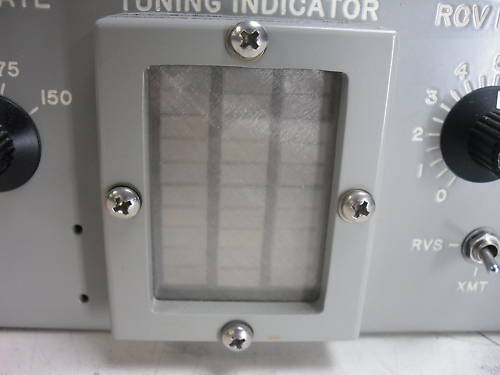
LED tuning indicator
manual NAVSHIPS 0967-LP-340-0010 Technical Manual for Comparator- Converter Group AN/URA-17F
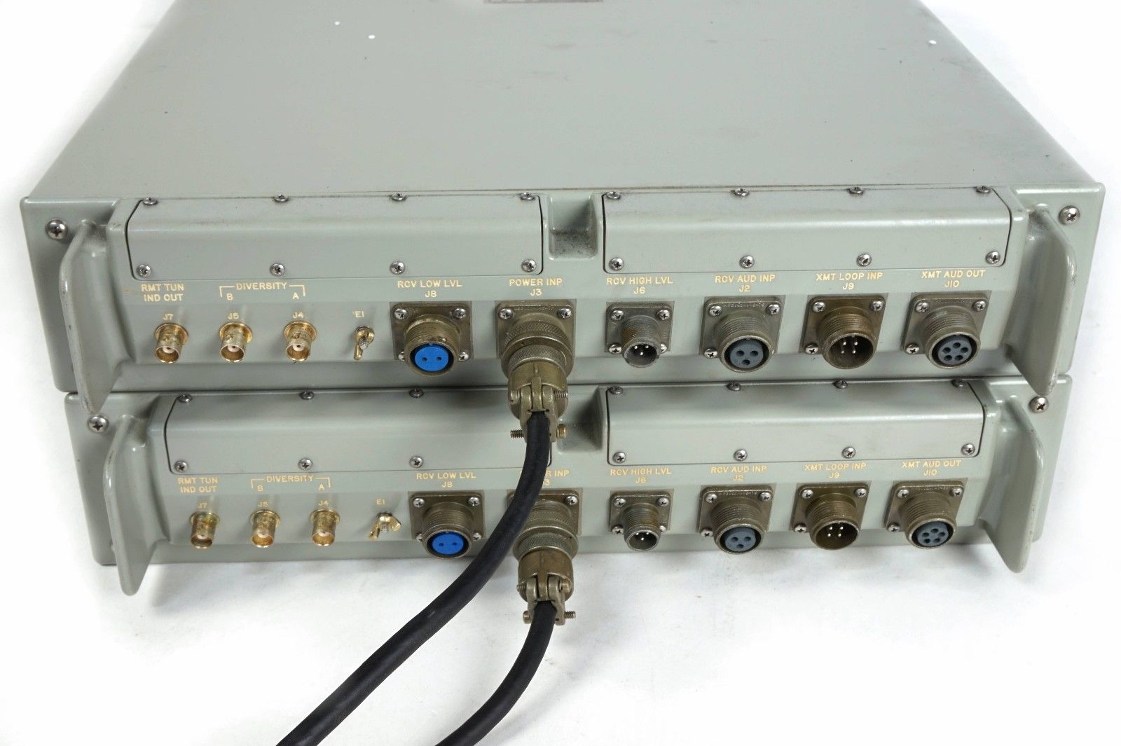
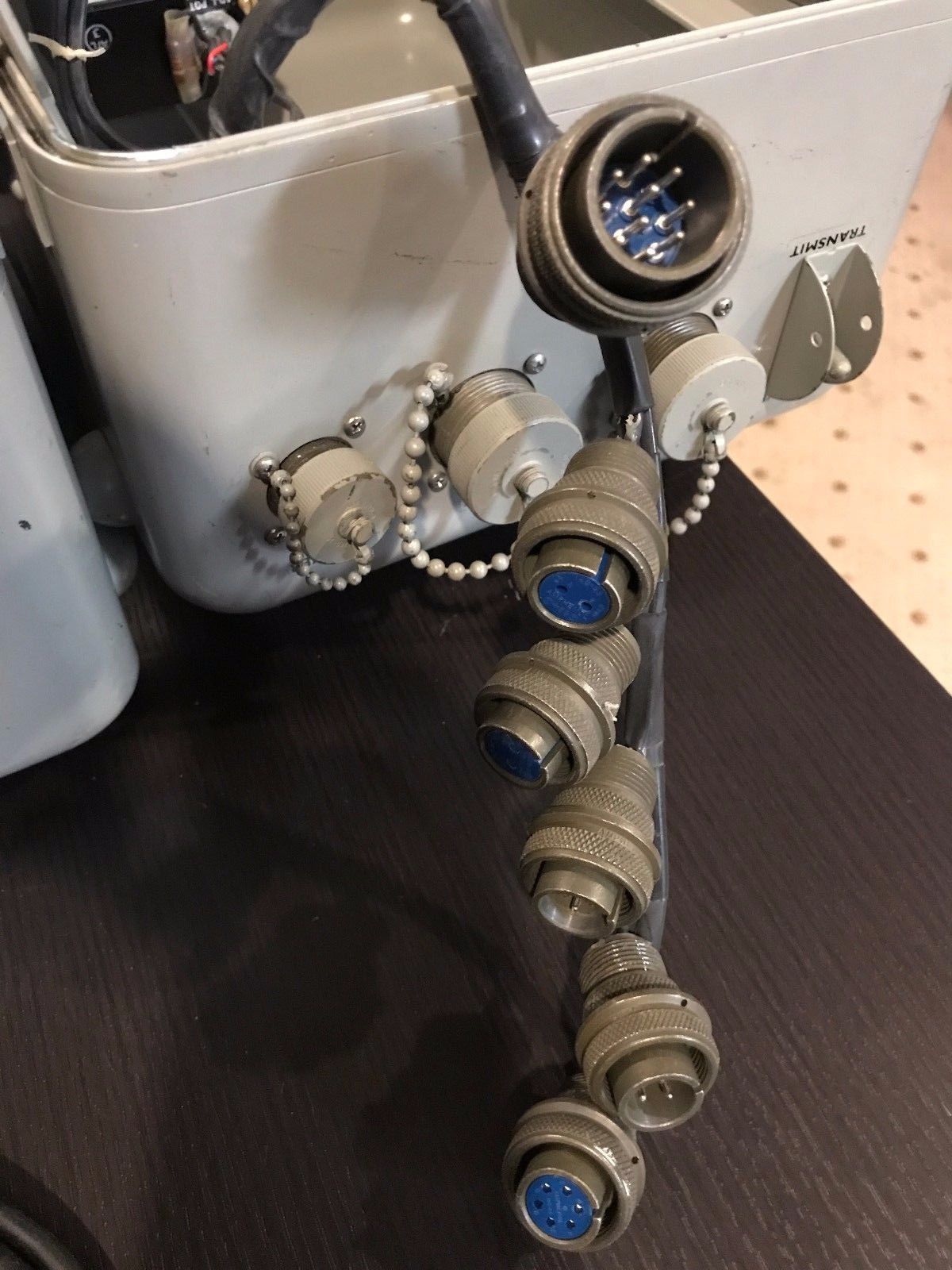
Left - high level neutral (60ma loop)
Mid - high level polar (20 ma loop)
Right - low level polar (+/-6v)
Left - Secure/sync mode
Rocker switches
Left - "back-to-back" mode
CV-3510C/UG
(part of AN/URA-17G)

LED indicator bars
Please send e-mail if you have a manual that I can buy or borrow to scan

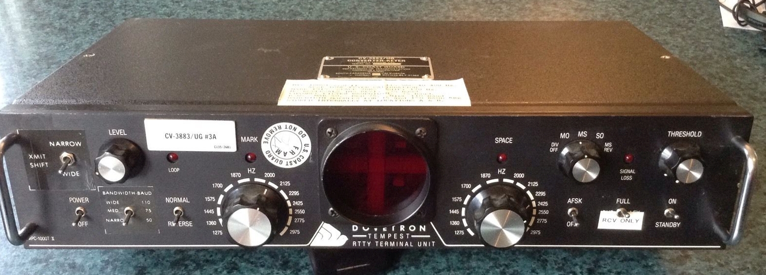
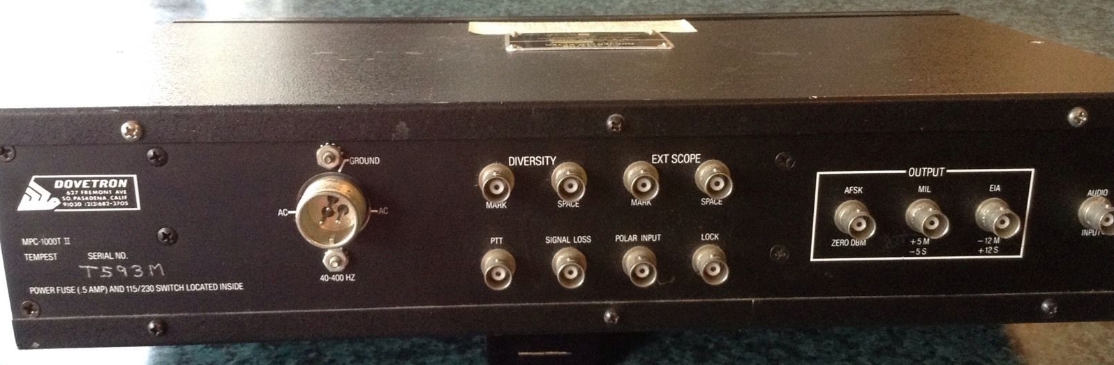
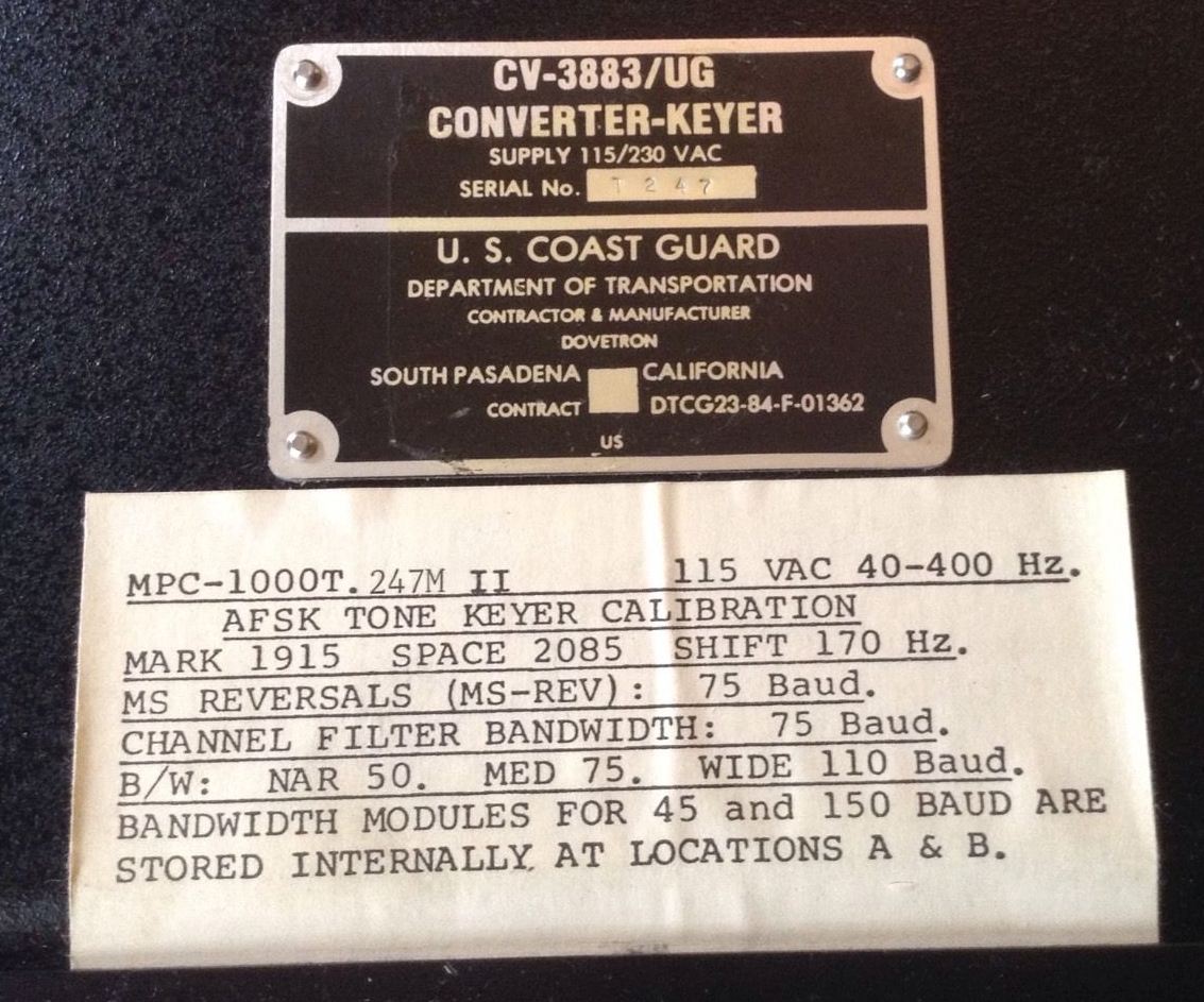
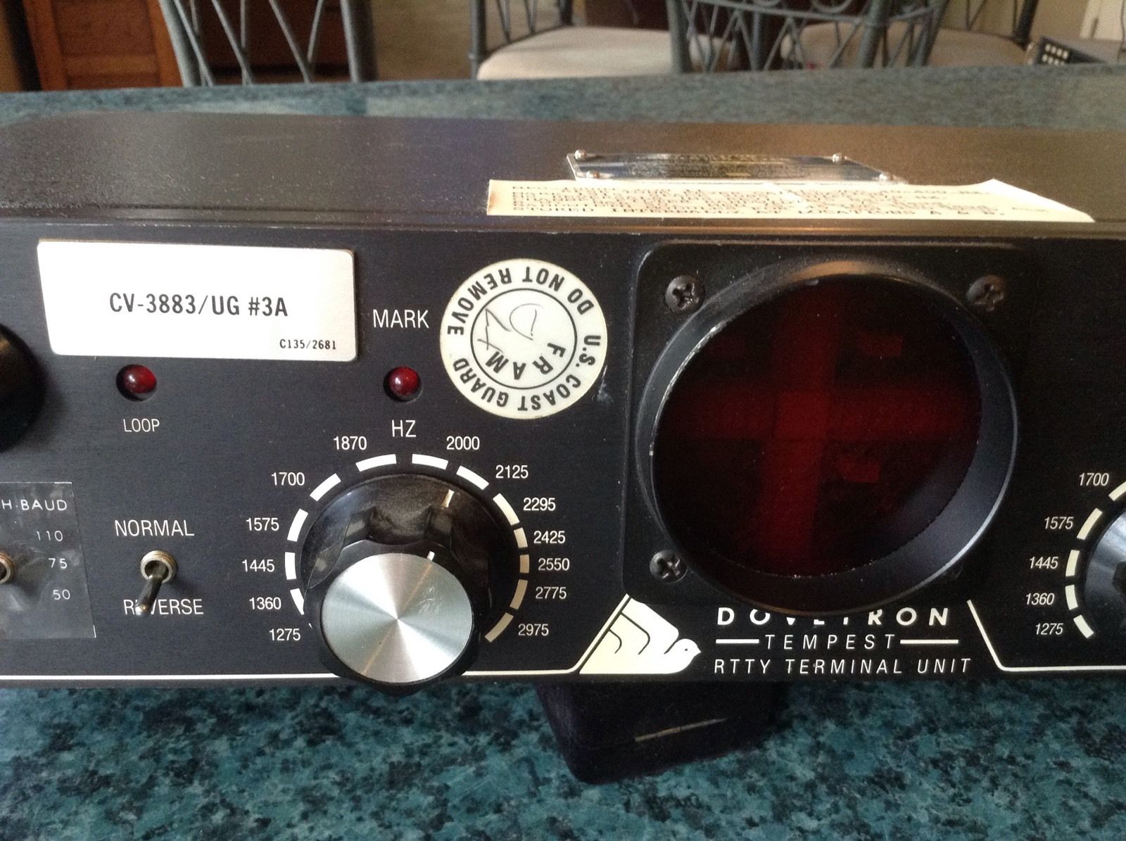
CV-3883/UG (Dovetron MPC-1000CR/T) TEMPEST
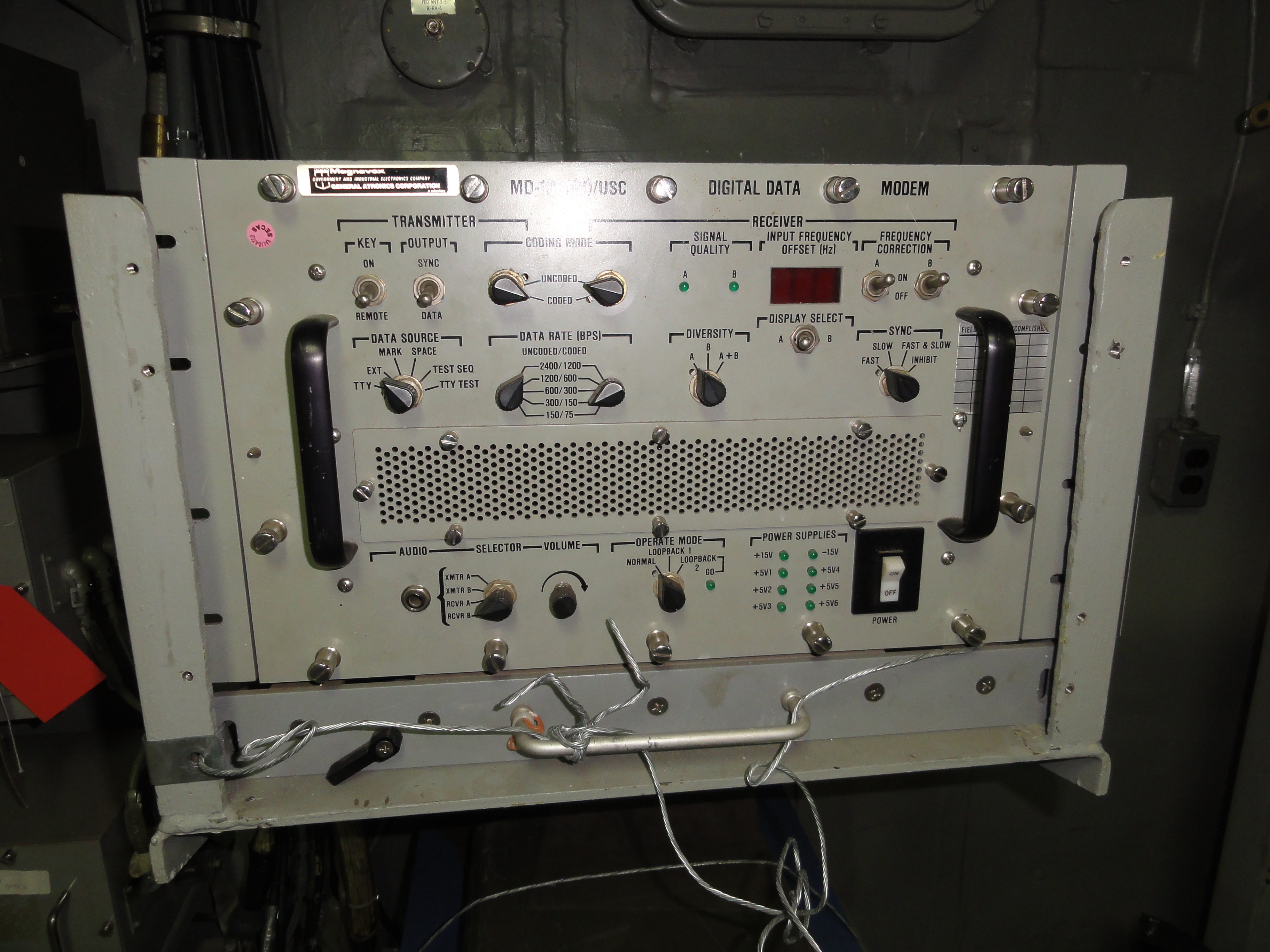
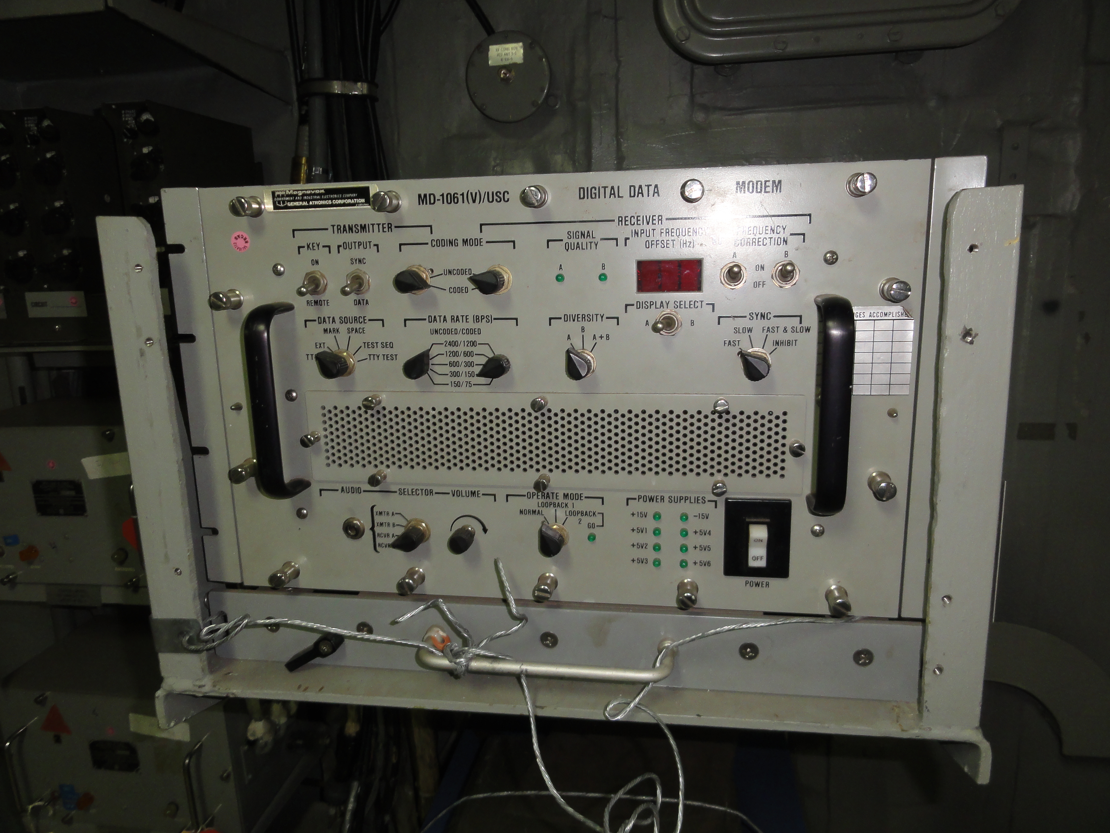
MD-1061(V)/USC Digital Modem

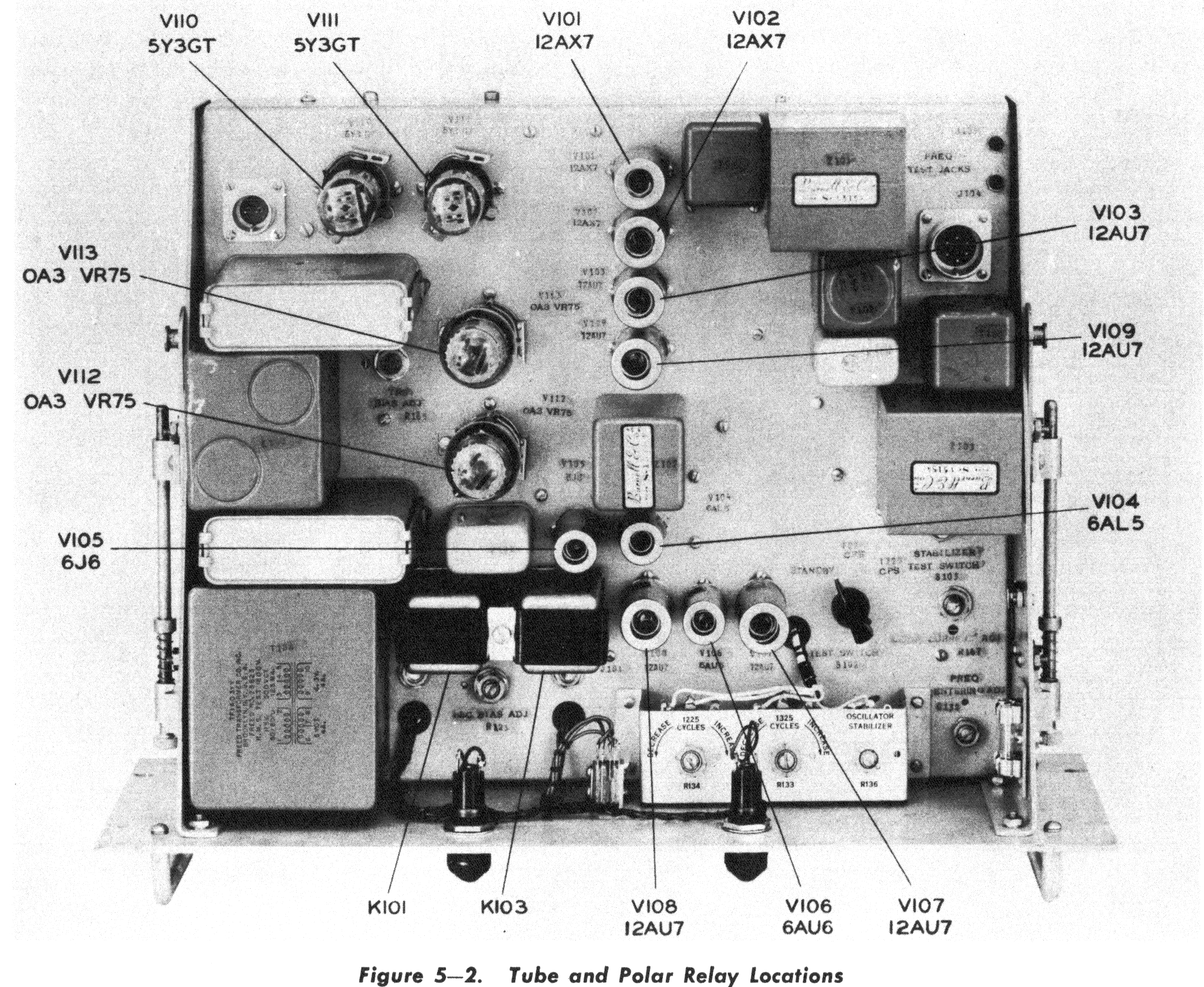
TH-20/UG
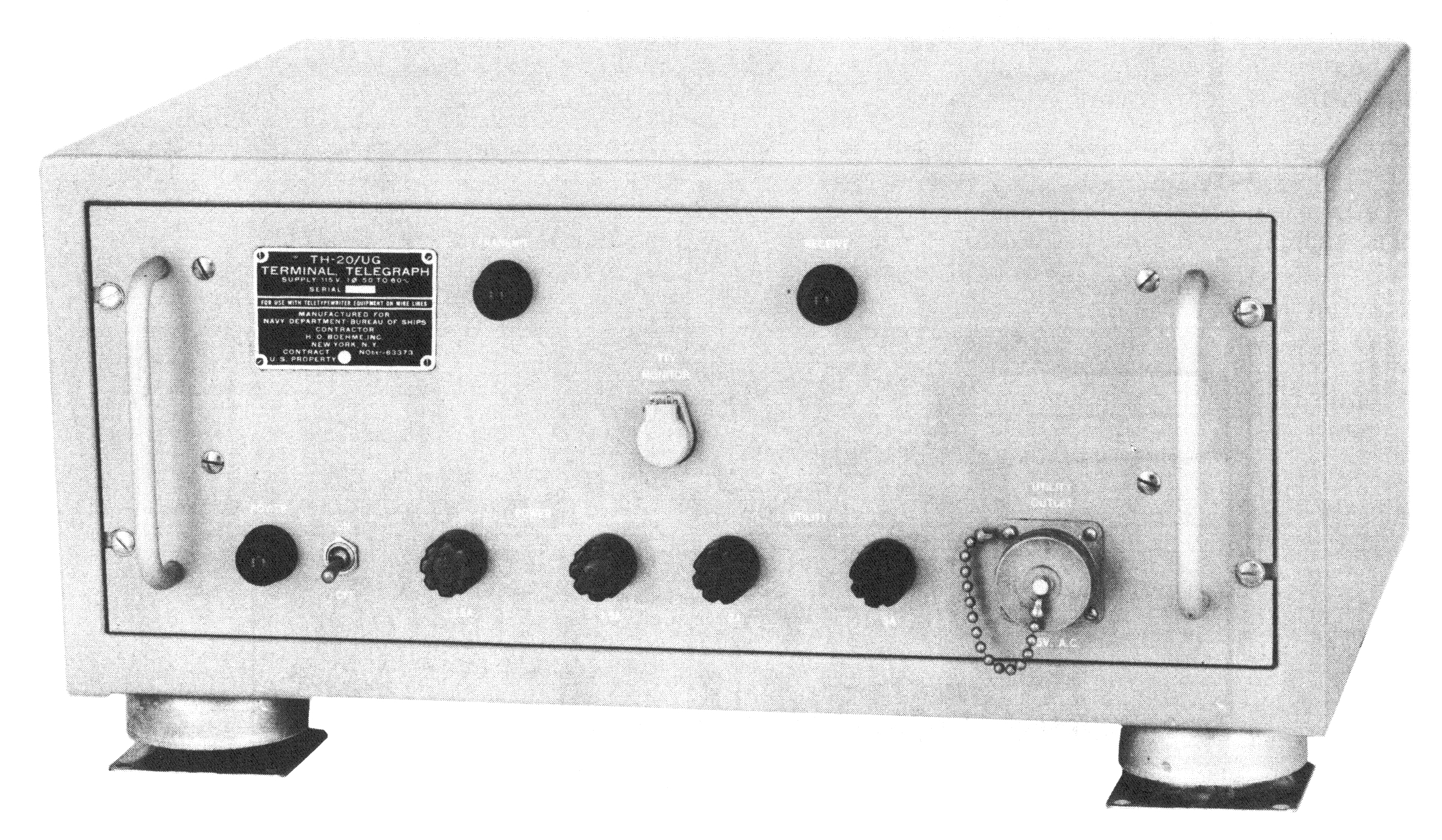

NAVSHIPS 92484
Harris RF-3352
![]()

+/- 0-597.5 Hz shift
50-150 baud
Neutral/Polar Loop input/output
internal loop supply
RS-232C input/output
Autostart relay


