AN/URT-2 AN/URT-3 AN/URT-4 Transmitter Information

Collection spot for miscellaneous info as I gather it
Please send me e-mail if you have any additions or corrections 

Back to Navy Transmitter Page
Back to K4NYW's URT-3 restoration page

Technical Article
"An automatic tuning communication transmitter"
Dettman, M.
IRE International Convention Record
Volume 1, Issue , Mar 1953 Page(s): 137 - 144
An essentially identical article is here beginning on page 271
An additional article on the automatic tuning system begins on page 279

Manuals
The 24 Feb 1953 "Temporary" instruction books NAVSHIPS 91833 is typewritten 
and missing a number of illustrations. Module removal and repair sections are also missing. 

The 91833(A) version is typeset and includes the missing sections.

Maintenance & Repair Training Notebook

Specification 
MIL-T-15480A (SHIPS)

Development - See also TEG Development
XTEJ description November 1945
XTEJ description (Westinghouse) September 1946
TEJ  Development Project
Nomenclature Change September 1950
        TEJ=>AN/URT-4, TEK=> AN/URT-2, TEL=> AN/URT-3
Federal Development began in 1947, prototype 1948, field test 1950
NObsr 43409   17 June 1949 Federal Telephone & Radio Corp.
NObsr 52021   01 Sept 1950 Federal Telephone & Radio Corp.
Approximate Cost
     AN/URT-2  $21,340 ea.
     AN/URT-3  $24,390 ea.
     AN/URT-4  $44,220 ea.

Output
AM/CW/FSK
URT-2 - 100 watts  300kc-26mc
URT-3 & URT-4 - 100 watts 300kc-2mc & 500 watts 2mc-26mc

Power requirements
Transmitter group - 115 vac single phase, 1000w 
Booster - 220 or 440 vac, 3 phase, 1800w

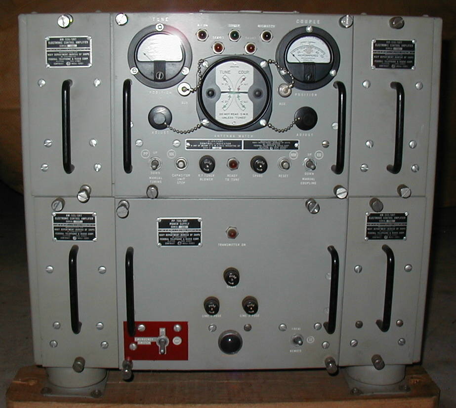
URT-4 equipment diagram
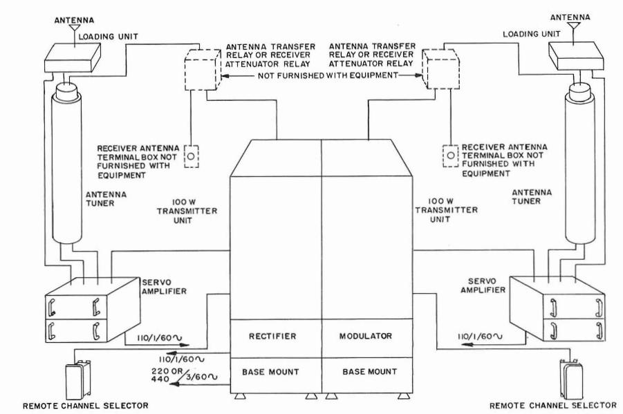
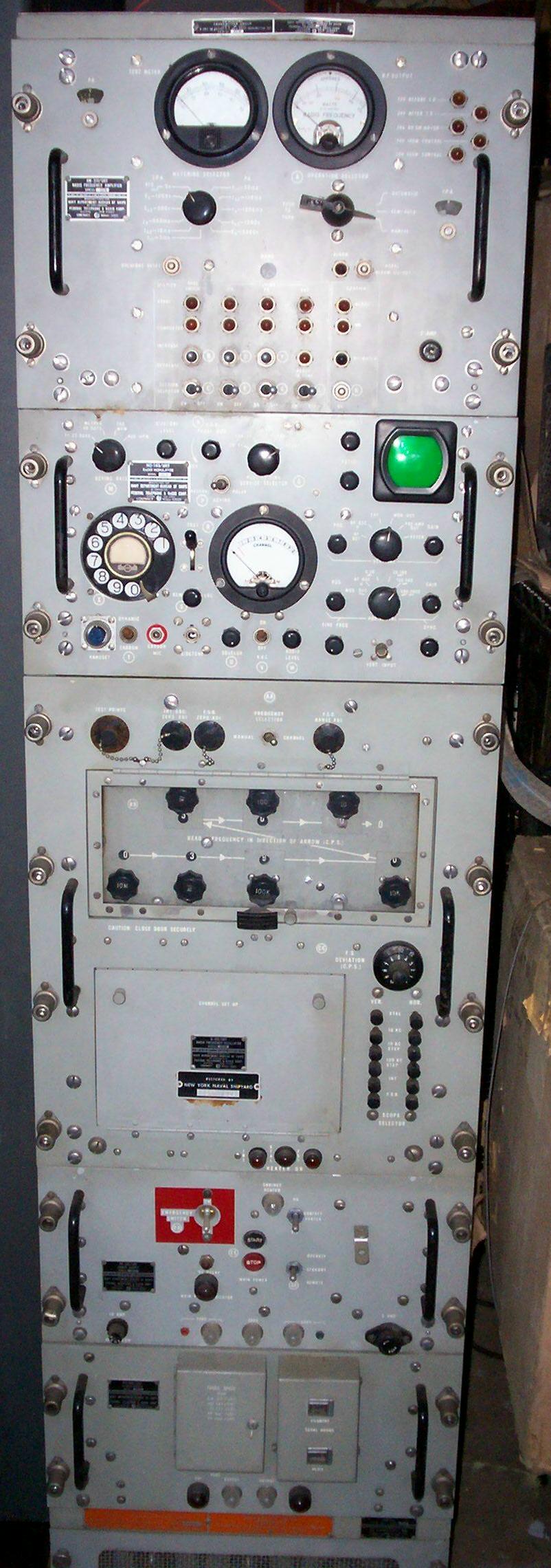
urt4-01.jpg (60143 bytes)

urt3-101.jpg (262325 bytes)
Transmitter

p1010001.JPG (99516 bytes)
Booster 

P1010008.JPG (91293 bytes)
Antenna Control Unit

More Photos - Antenna Tuner and other Accessory Units


THE XTEJ-SERIES TRANSMITTING EQUIPMENTS (from 1952 Introduction to Radio Equipment NAVPERS 10172-A)

  This series of transmitting equipments incorporates the very latest design and engineering in mechanical as well as electrical features, and will eventually replace many other types of transmitters of earlier design. It is very versatile in that the major circuit elements are made up into separate units, thus providing a sort of "building-block" system from which many types of equipment can be assembled. At present there are three standard types in the series, known as the AN/URT-2, -3, and -4.
  The AN/URT-2 consists of the minimum number of basic units, and has a power output of 100 watts. The AN/URT-3 is the same, with the addition of a 500-watt booster amplifier and its associated power supply, thus providing optional output power of 100 or 500 watts. The AN/URT-4 consists of two of the AN/URT-2 equipments plus the booster amplifier, thus providing two entirely independent transmitting channels of 100 watts output, with the 500-watt booster amplifier available for use with either channel when desired. This arrangement is shown in figure 163. Note particularly the great saving in size.
  All equipments cover the frequency range 0.3 to 26 Mc. Since the frequency-generating unit is designed to produce all frequencies in this range, no doublers or other frequency-multiplier stages are required in the transmitter. The frequency-generating unit, intermediate amplifier stages, and the final amplifier all function at the desired operating frequency. Up to ten pre-tuned channels may be selected by means of a telephone dial.
  The equipment is capable of operation on c-w on-off and frequency-shift telegraphy, including teletype and facsimile, and voice modulation. Vacuum-tube keying circuits insure accurate keying even at very high speeds.
  Output circuits feed a standard 50-ohm coaxial transmission line, which terminates in an automatic antenna tuning unit located near the antenna. This method permits the adjustment of the antenna to the proper impedance to match the transmission line, so that transmitter, line, and antenna all operate at maximum efficiency regardless of frequency or type of antenna.

Components

UNIT MODULE DESCRIPTION
OA-353/URT transmitter group
  AM-519/URT RF amplifier, RFA
  MD-143/URT low level modulator, LLRM
  O-153/URT radio frequency oscillator, RFO
  PP-667/URT low voltage power supply, LVPS
  PP-668/URT medium voltage power supply, MVPS
  CY-992/URT cabinet
     
OA-354/URT Booster - modulator-power supply group
  MD-149/URT high level modulator, HLRM
  PP-707/URT high voltage power supply, HVPS
  CY-993/URT HLRM cabinet
  CY-994/URT HVPS cabinet
  CW-287/URT booster cover
  MT-958/URT mounting with blowers
OA-297/URT ACG antenna control group
  C-915/URT Control Indicator 
  AM-555/URT Electronic Control Amplifier (2 ea.)
  AM-556/URT Electronic Control Preamplifier (2 ea.)
  PP-708/URT Power Supply 
  CY-1047/URT cabinet 
TN-197/URT antenna tuner (inductor)
CB-5/URT capacitor assembly (tuner)
C-916/URT transmitter remote control
Test equipment    
  ME-88/U RFO RF voltmeter
  DA-91/U transmitter bay dummy load
  TS-803/URT RF Tuner test set
  TS-804/URT ACG test set
  OA-466/URT 8' transmitter extender cable set w/ case (for URT-2)
  OA-494/URT 8' transmitter + booster extender cable set w/ case (for URT-3, -4)