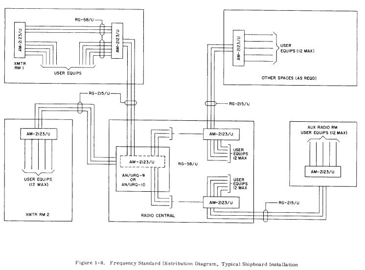
Typical Shipboard Frequency Standard Distribution System
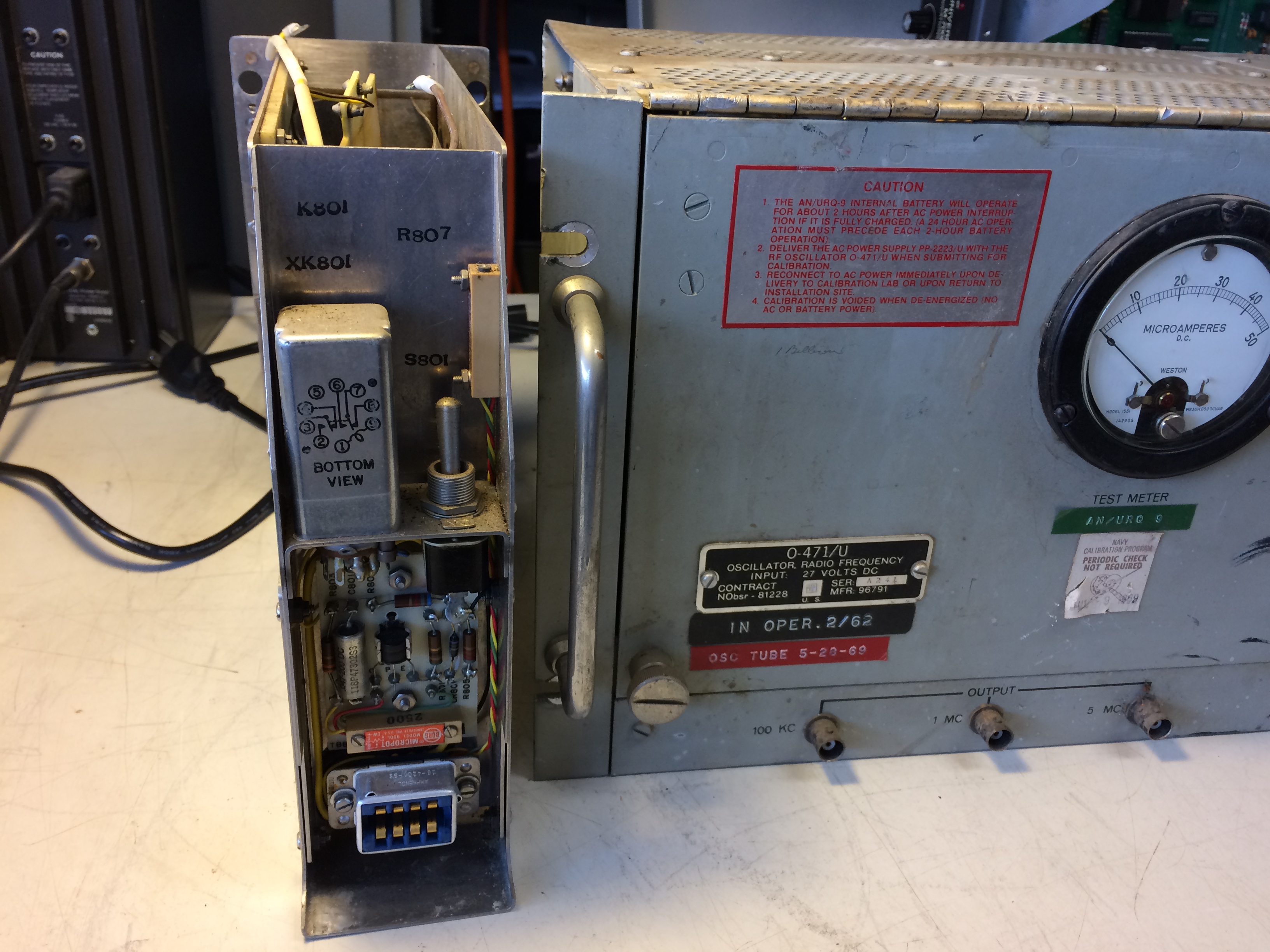
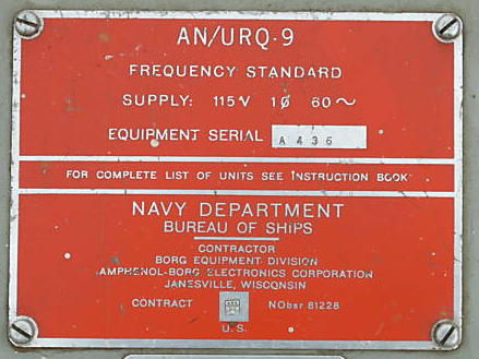
| AN/URQ-9 Frequency Standard
|
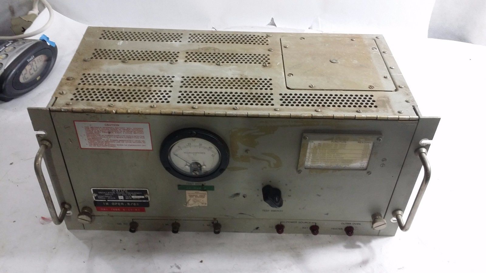
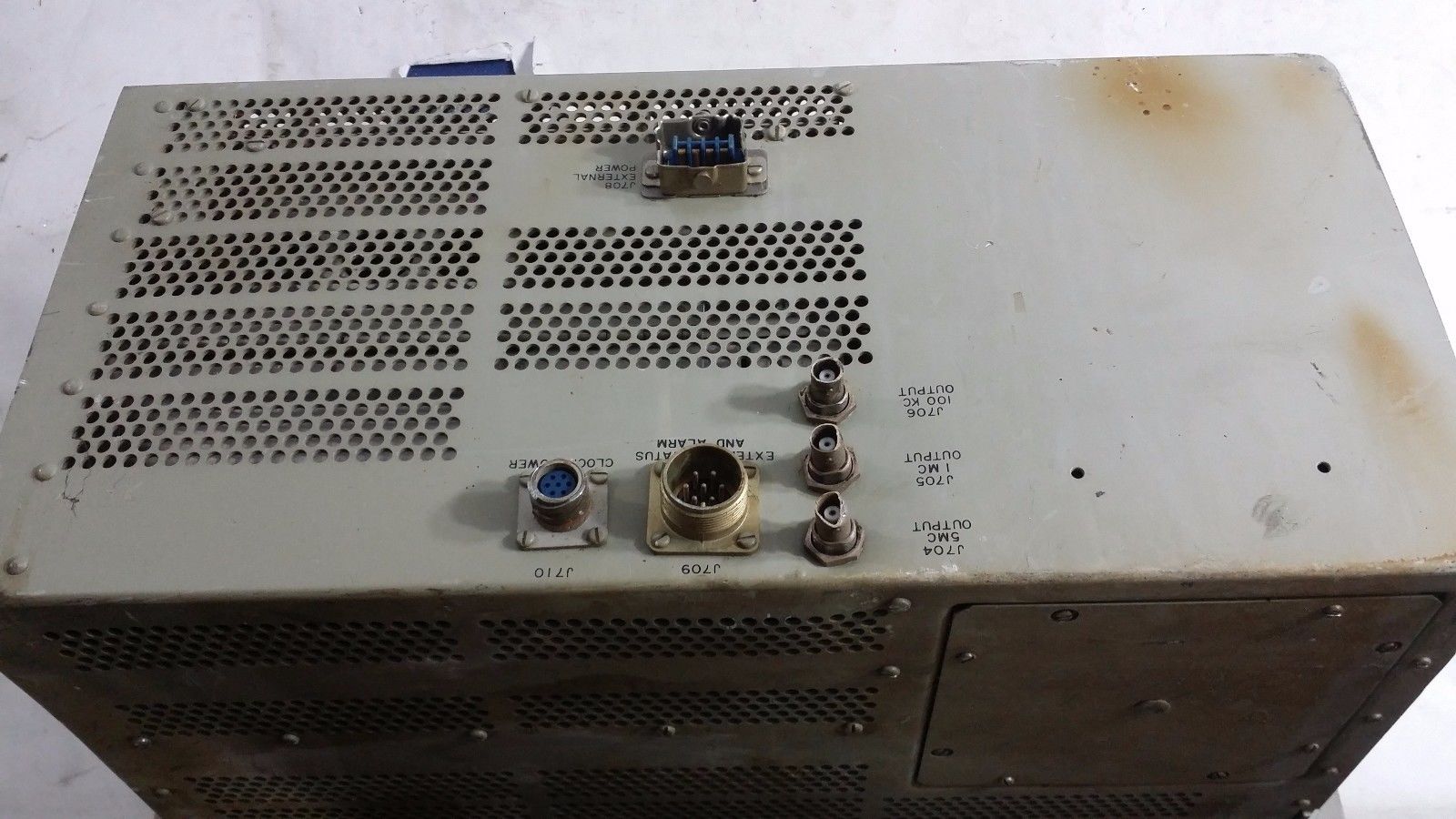
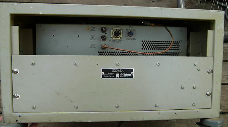
O-471/U Oscillator PP-2223/U Power Supply
|
 |
NAVSHIPS 93221 NAVSHIPS 93806(A) NAVSHIPS 0967-LP-077-8010 |
 |
 |
 |
|
 |
 |
 |
|
 |
 |
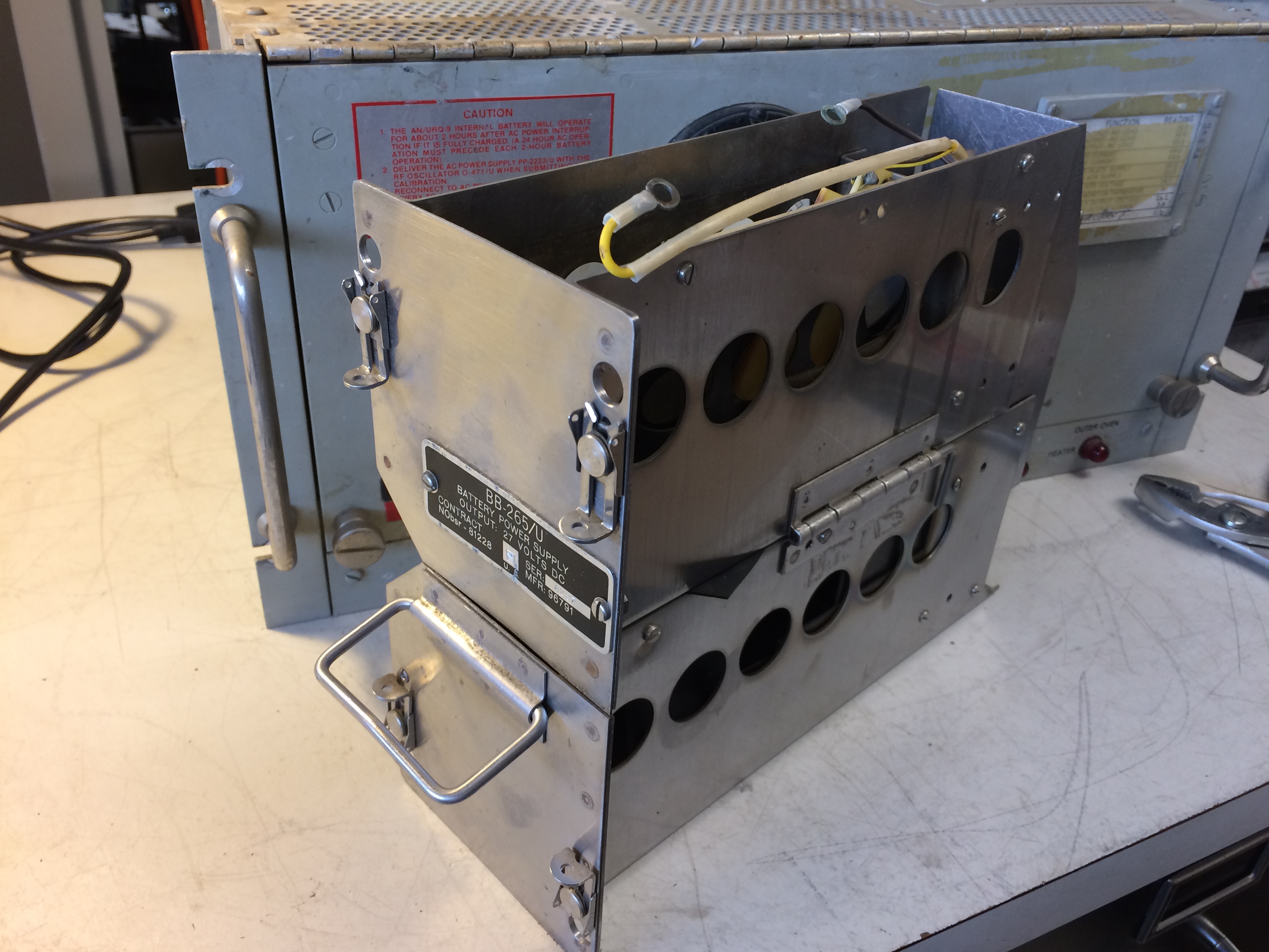
Removable NiCad battery compartment | 
|
 |
 |
 |
-- |
|
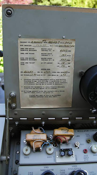
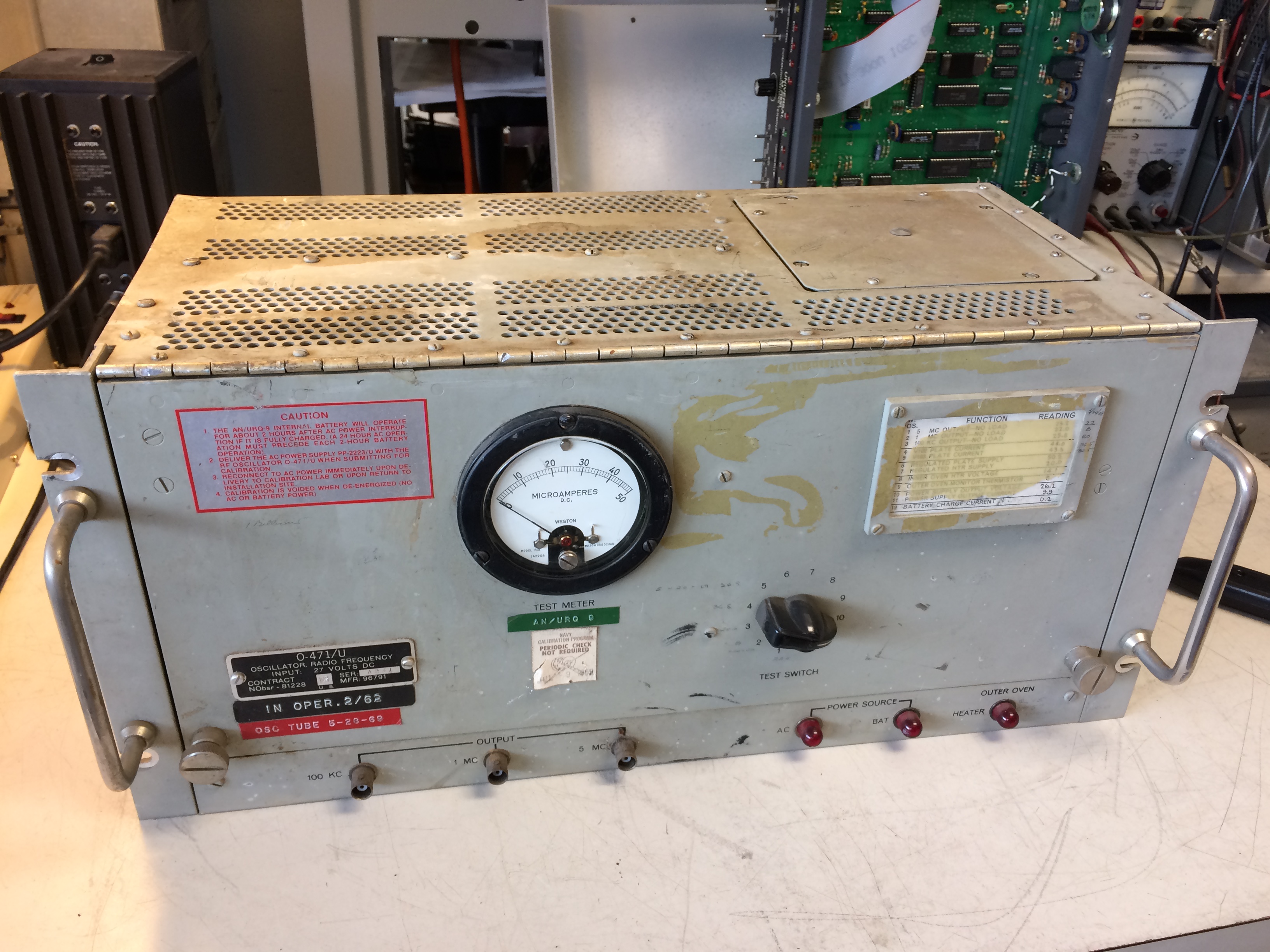
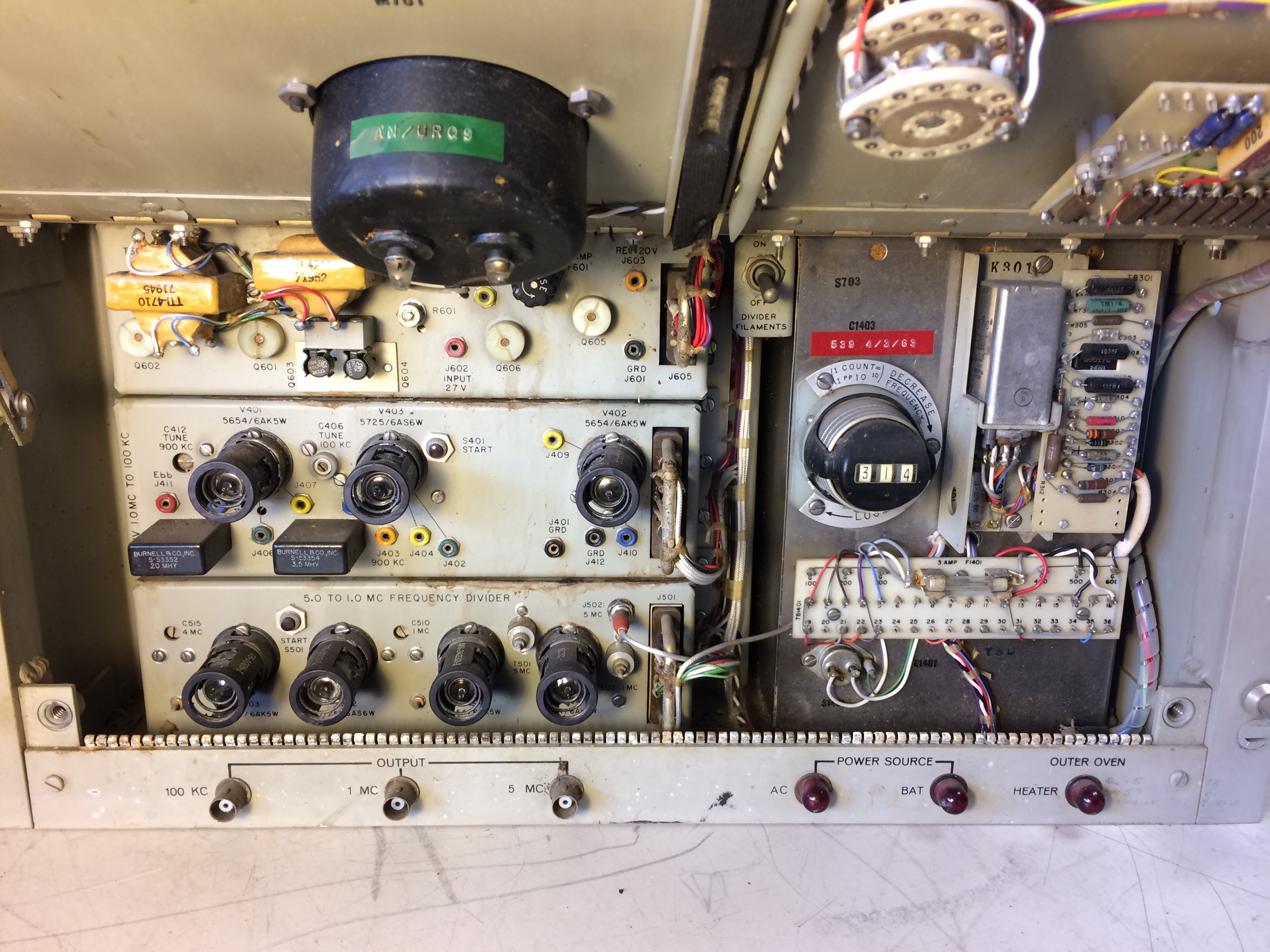
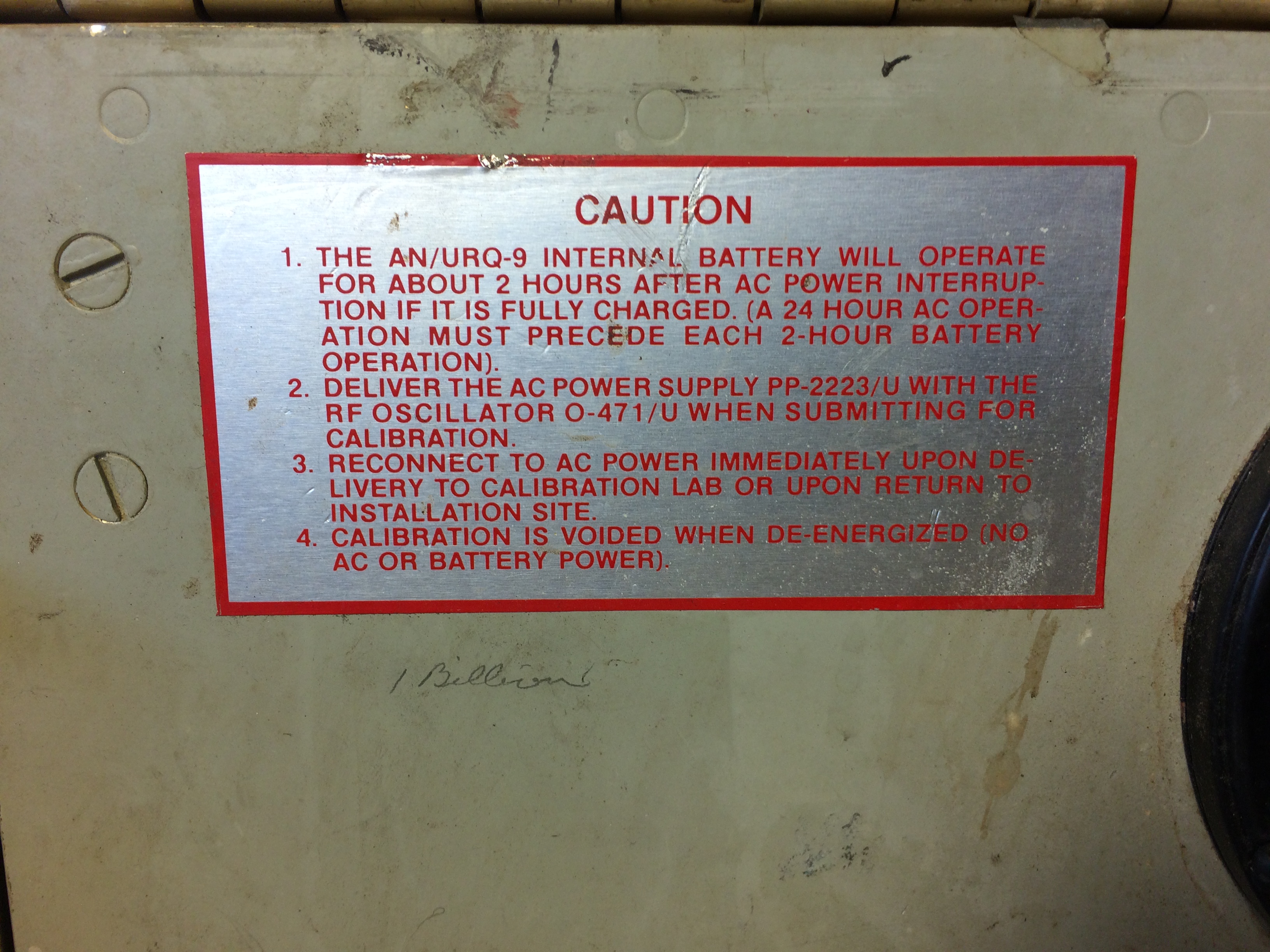
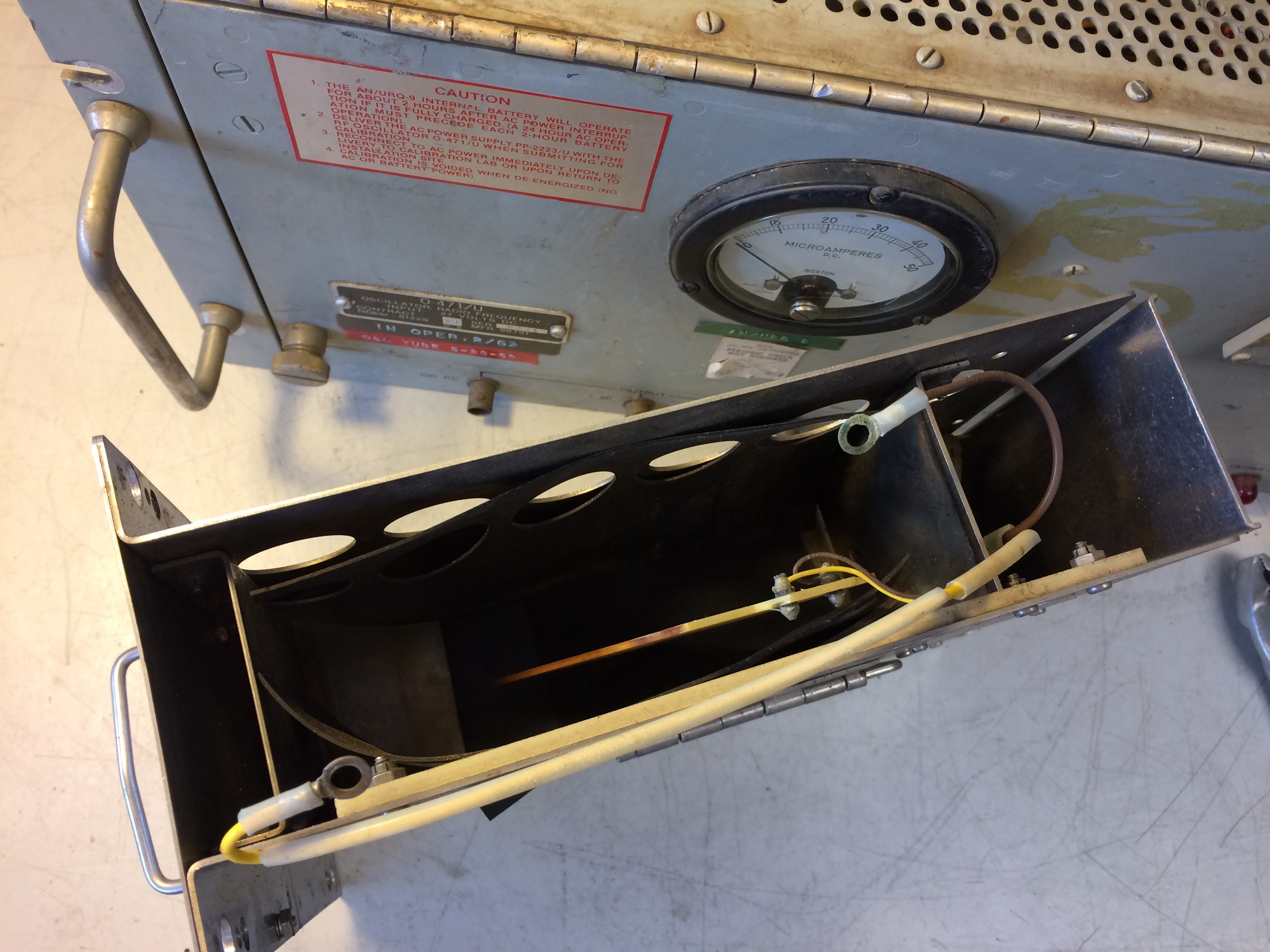
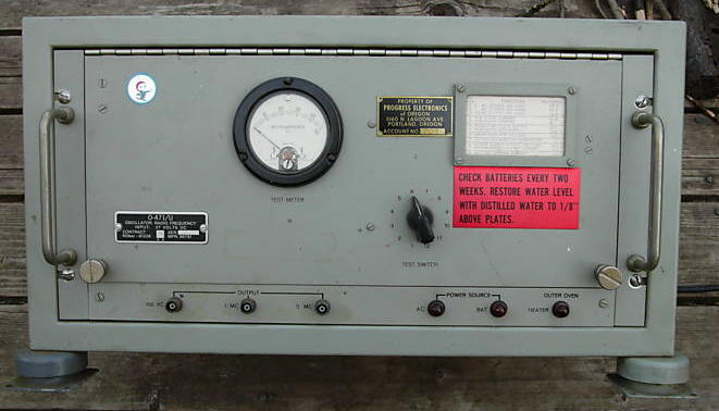
This highly stable frequency standard is designed for
continuous-duty use aboard ships and at shore facilities. It has three fixed output frequencies: 5 mc, 1 mc, and 100 kc. Because it is intended as a frequency standard against which other frequency-generating equipment can be compared, the AN/URQ-9 is energized and calibrated at special calibration laboratories. Once it is placed in operation and is calibrated properly, the frequency standard must not be turned off. Any interruption in its operation will cause a change in its output frequencies. Hence, the equipment is transferred to the using activity while still operating. A battery, which is built into the equipment, maintains operation during the time the frequency standard is in transit. It also supplies power to the unit in the event of power failure aboard ship. When fully charged, the battery is capable of operating the equipment for approximately 2 hours. |
|||
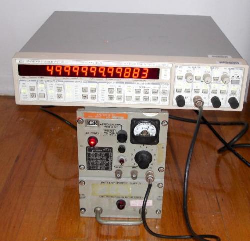
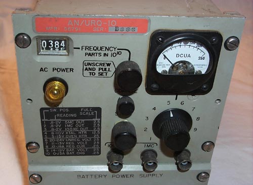
AN/URQ-10 Frequency Standard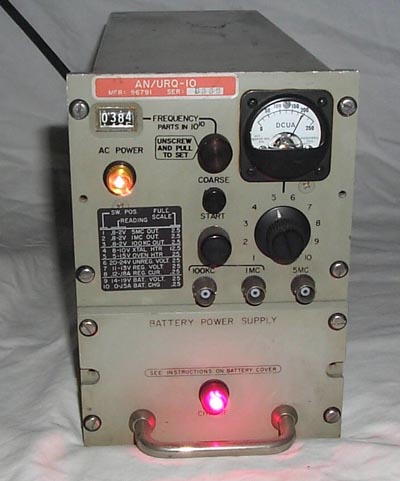
|
Solid-state version of URQ-9
8 hour battery life
|
 |
Manual NAVSHIPS 0967-053-7010
|
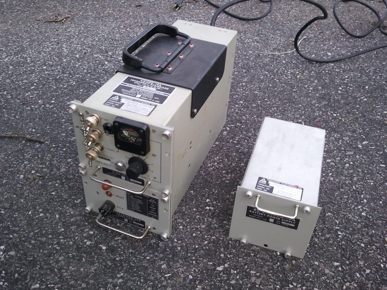
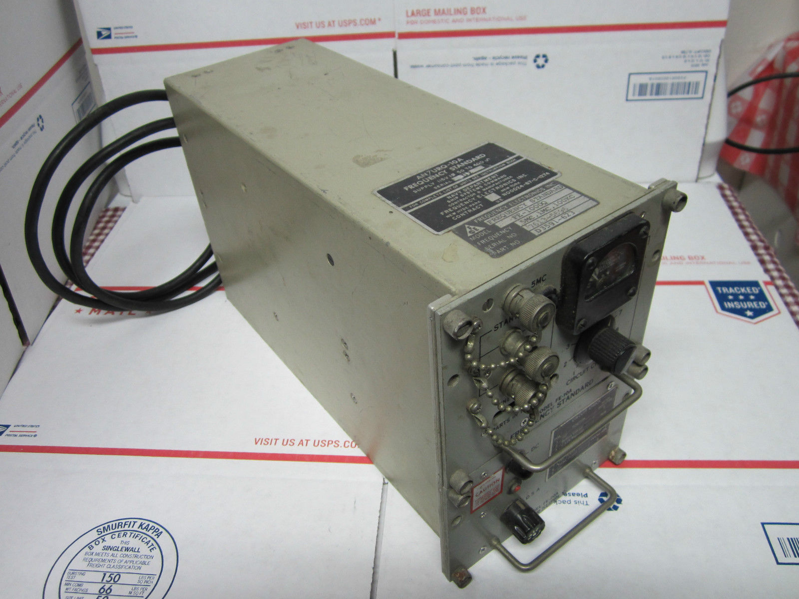
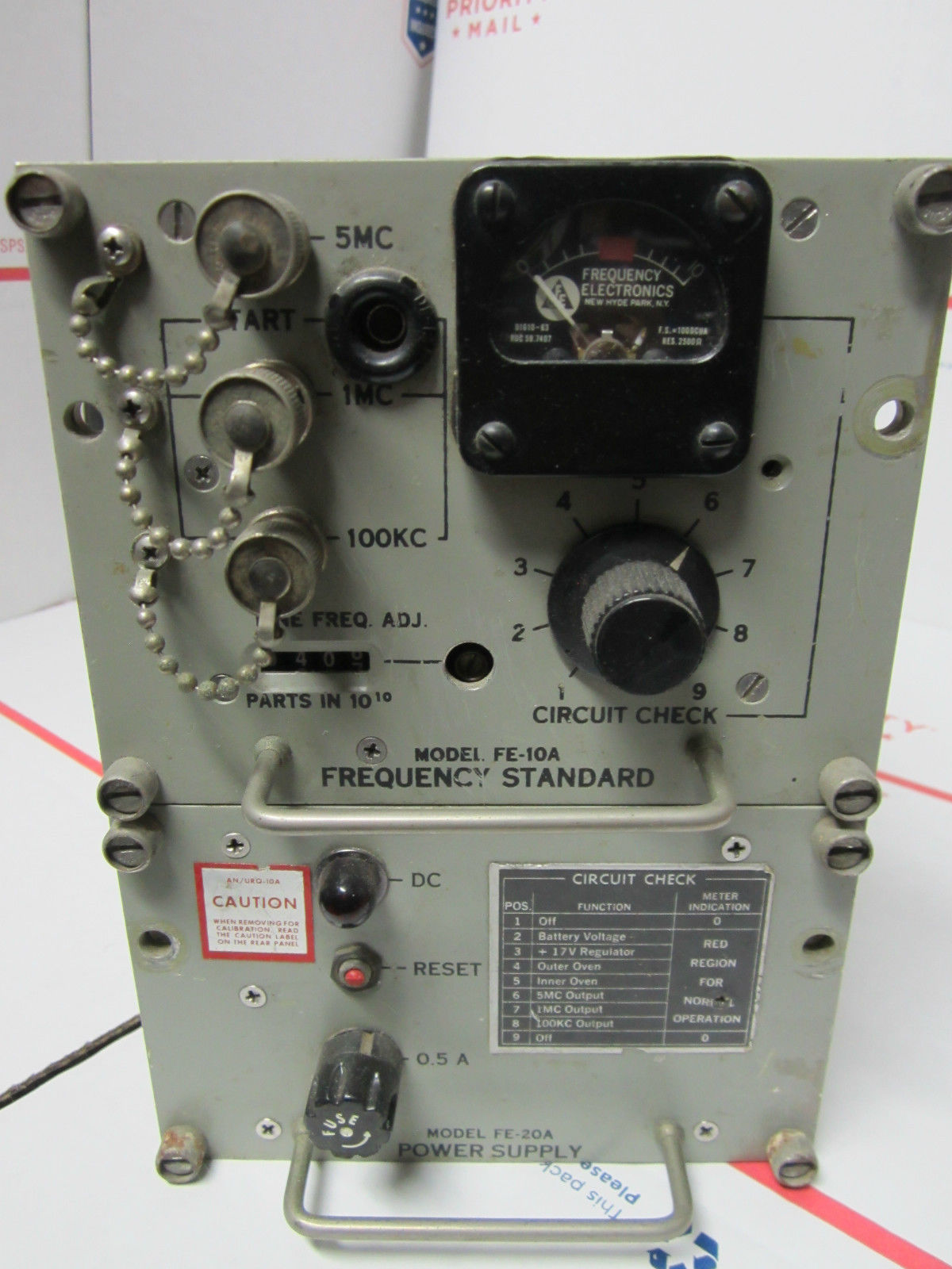
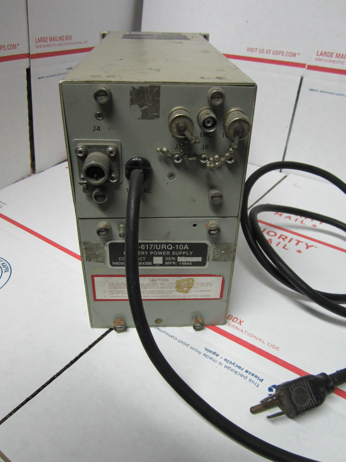
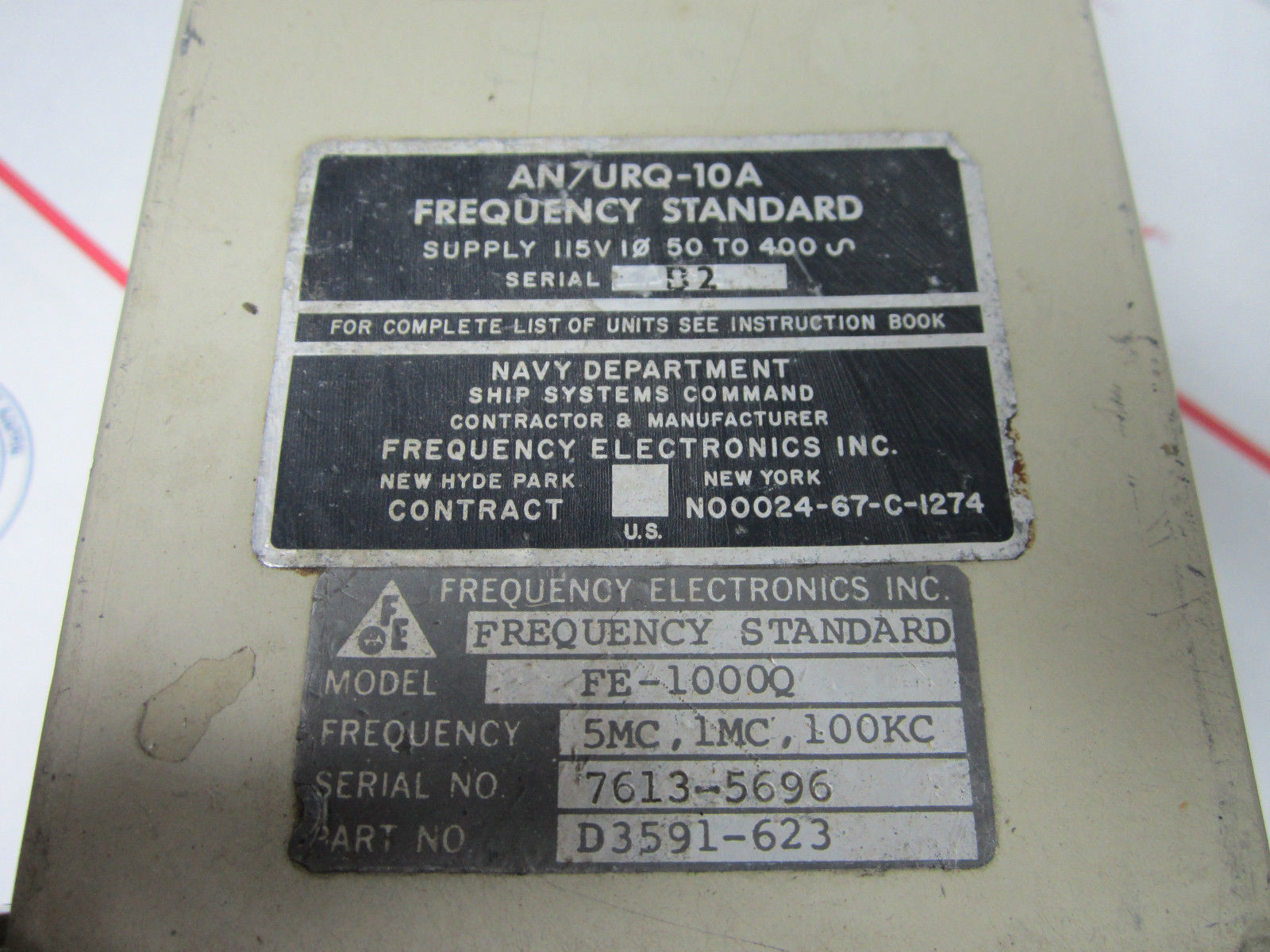
AN/URQ-10A Frequency Standard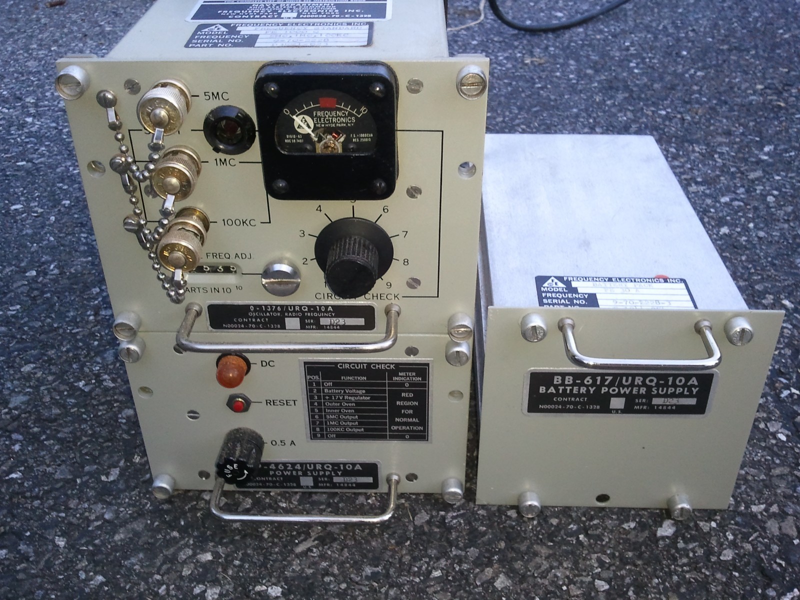
|
|
 |
Manual NAVSHIPS 0967-170-3010
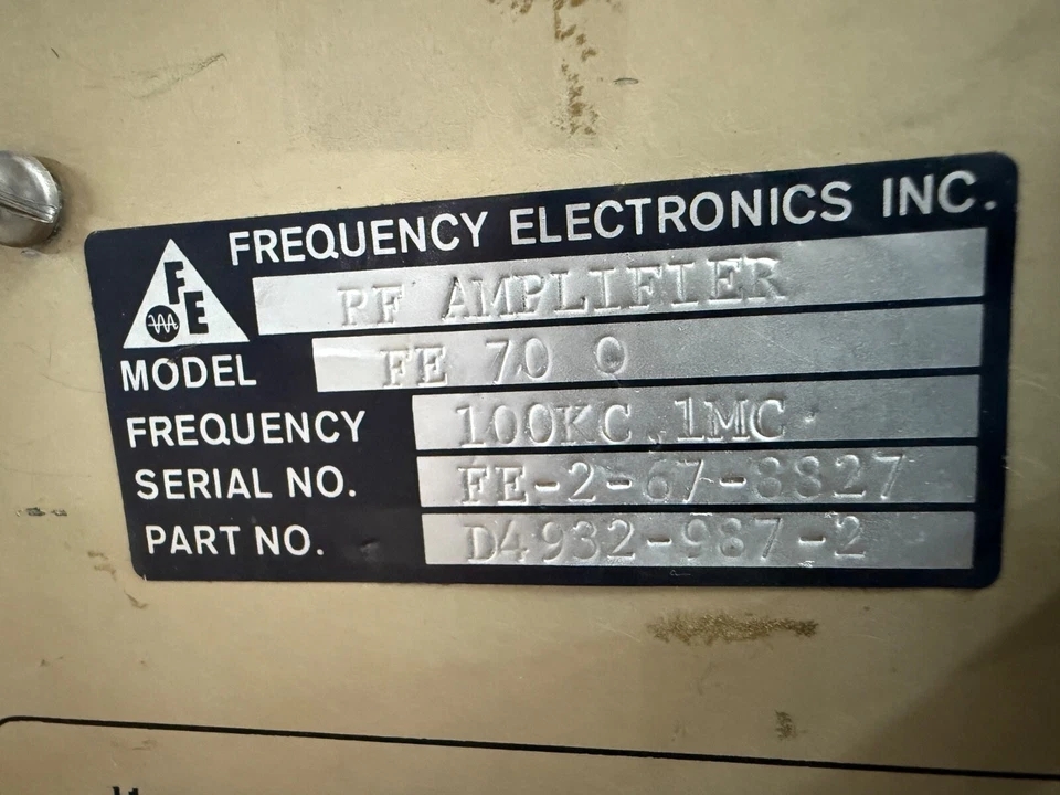
Frequency Electronics Inc. FE-10A
|
|
|
 |
|
AN/URQ-13 Centralized Frequency & Time Control System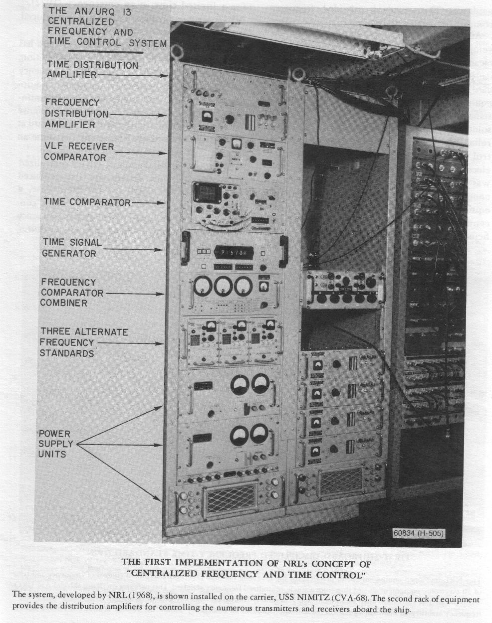 With
the continuing rapid proliferation of electronic equipments aboard ship,
the Navy has been faced with a serious problem of accommodating all the
equipments for carrying out necessary command and control functions in the
limited space available. Some aspects of this problem also exist at the
Navy's shore stations. The electronic equipments must be precisely
controlled in frequency to avoid mutual interference, to insure
reliability in maintaining communication-circuit continuity, and to use
the radio spectrum economically. The equipments also require precise time
and time interval for their respective functions. Provision of individual
standards of highest precision for each equipment would involve further
demand for space and added complexity. This situation led NRL to conceive
of a centralized frequency and time control system in which a standard of
highest precision would control all the frequency and time functions
involved from a central point. Synthesizers, located at the individual
equipments, would then produce the desired output for the frequency and
time functions. It would then be feasible to provide the central standard
with adequate space to insure the highest degree of precision (1955). NRL
developed several models of the system, to establish the principles and
illustrate the features involved. Many demonstrations of these models were
given to cognizant high Navy officials to show the utility of the concept.
The first implementation of NRL's concept of centralized frequency and
time control took place with the installation of part of the system on the
carrier USS NIMITZ (CVA-68). This installation included the centralized
frequency and time standard, the AN/URQ-13 (XN-2), developed by a
contractor under NRL's guidance. This standard provided frequency control
for many transmitters and receivers. An important difficulty encountered
in developing the system was the lack of provision of means for
controlling the outputs of the individual equipments, should the precise
central standard fail or the transmission line to an individual equipment
be disrupted. Additional precise standards at the central point would
provide a solution for only part of the problem. To insure reliability in
the system of centralized control of frequency and time functions of many
electronic equipments aboard ship, NRL was first to develop an oscillator,
compact enough to be housed in individual electronic equipments, normally
servo-controlled by the centrally located standard, but having sufficient
stability to maintain proper operation for a limited time in an emergency
(1972). NRL's servo-controlled oscillator was produced under the
designation AN/URQ-23. With
the continuing rapid proliferation of electronic equipments aboard ship,
the Navy has been faced with a serious problem of accommodating all the
equipments for carrying out necessary command and control functions in the
limited space available. Some aspects of this problem also exist at the
Navy's shore stations. The electronic equipments must be precisely
controlled in frequency to avoid mutual interference, to insure
reliability in maintaining communication-circuit continuity, and to use
the radio spectrum economically. The equipments also require precise time
and time interval for their respective functions. Provision of individual
standards of highest precision for each equipment would involve further
demand for space and added complexity. This situation led NRL to conceive
of a centralized frequency and time control system in which a standard of
highest precision would control all the frequency and time functions
involved from a central point. Synthesizers, located at the individual
equipments, would then produce the desired output for the frequency and
time functions. It would then be feasible to provide the central standard
with adequate space to insure the highest degree of precision (1955). NRL
developed several models of the system, to establish the principles and
illustrate the features involved. Many demonstrations of these models were
given to cognizant high Navy officials to show the utility of the concept.
The first implementation of NRL's concept of centralized frequency and
time control took place with the installation of part of the system on the
carrier USS NIMITZ (CVA-68). This installation included the centralized
frequency and time standard, the AN/URQ-13 (XN-2), developed by a
contractor under NRL's guidance. This standard provided frequency control
for many transmitters and receivers. An important difficulty encountered
in developing the system was the lack of provision of means for
controlling the outputs of the individual equipments, should the precise
central standard fail or the transmission line to an individual equipment
be disrupted. Additional precise standards at the central point would
provide a solution for only part of the problem. To insure reliability in
the system of centralized control of frequency and time functions of many
electronic equipments aboard ship, NRL was first to develop an oscillator,
compact enough to be housed in individual electronic equipments, normally
servo-controlled by the centrally located standard, but having sufficient
stability to maintain proper operation for a limited time in an emergency
(1972). NRL's servo-controlled oscillator was produced under the
designation AN/URQ-23.
A prototype installation of NRL's system has been established at the Navy's radio station, Wahiawa, Hawaii, for the centralized frequency and time control of its many electronic equipments. The local standard at Wahiawa is continuously referenced via the Department of Defense Satellite Communication System to the standard at the Naval Observatory. This is the first time an operation of this type has been accomplished. A prototype installation of NRL's centralized frequency and time system was also produced for ships. It provided, for the first time, a comprehensive implementation of NRL's concept of the centralized control of the frequency and time functions involved in communication. From "Evolution of Naval Radio-Electronics and Contributions of the Naval Research Laboratory" (Gebhard) - 25MB pdf |
|||
|
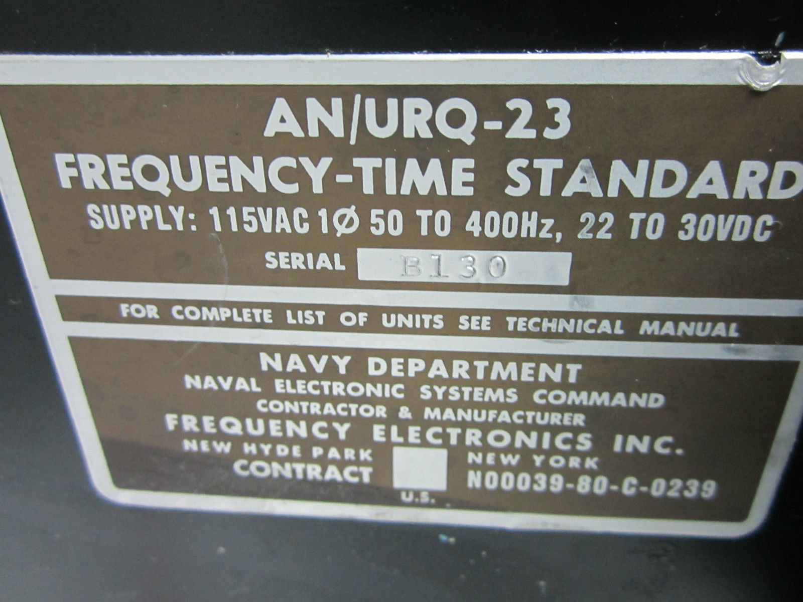
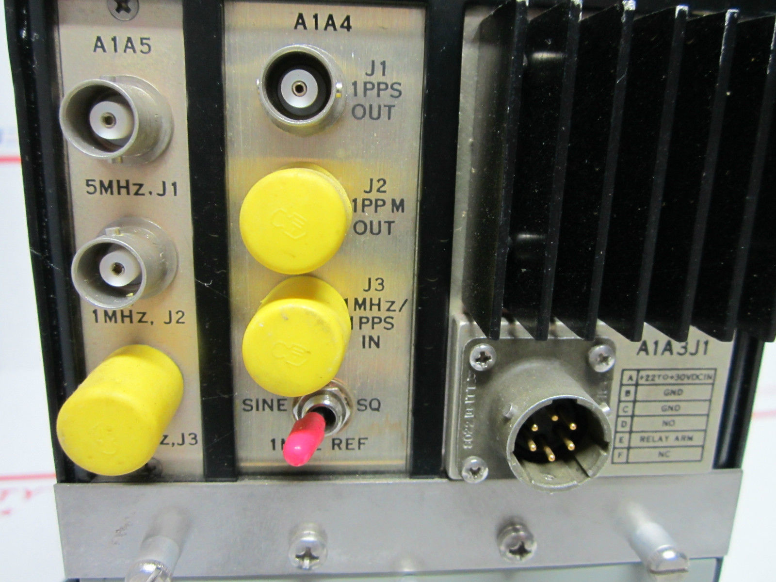
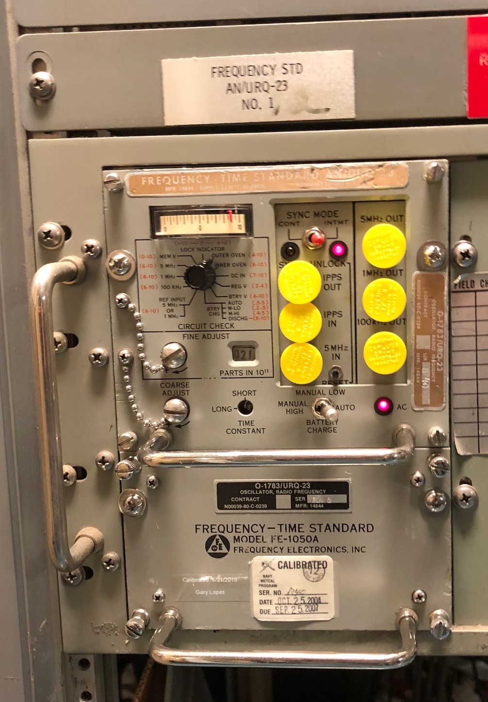
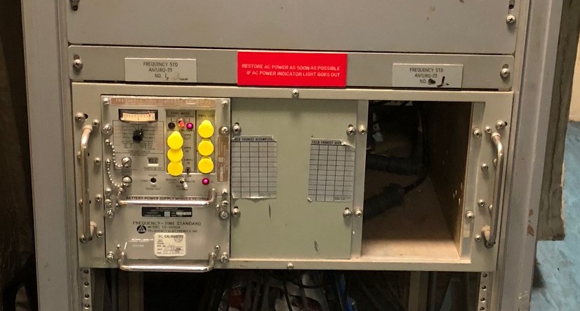
AN/URQ-23 Frequency-Time Standard
|
Frequency Electronics Inc. FE-1050A
AN/URQ-23 aboard USS Iowa |
 |
|
 |
 |
 |
 |
O-1107/SRC-16 Frequency Standard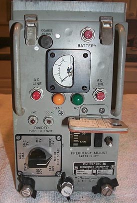 |
Part of AN/SRC-16 Communications System | - | - |
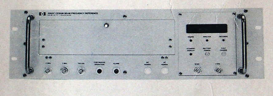
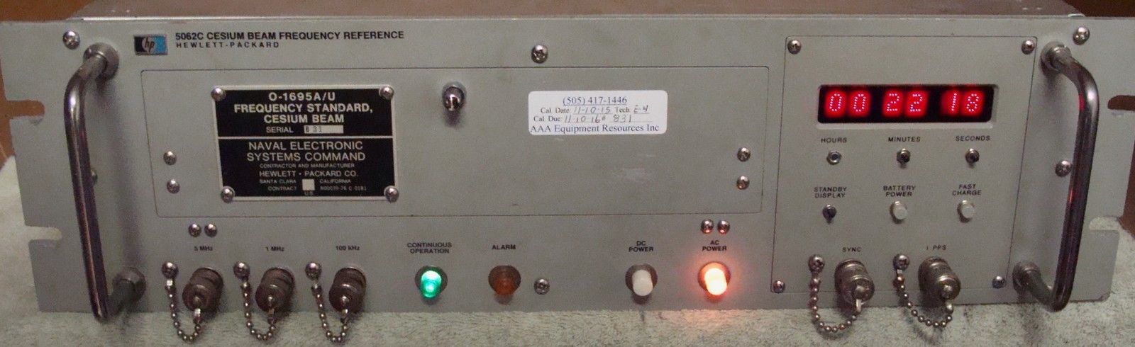
| O-1695/U, O-1695A/U (HP 5062C) Cesium Beam Standard
|
 |
Manual is 0969-LP-171-6020
|
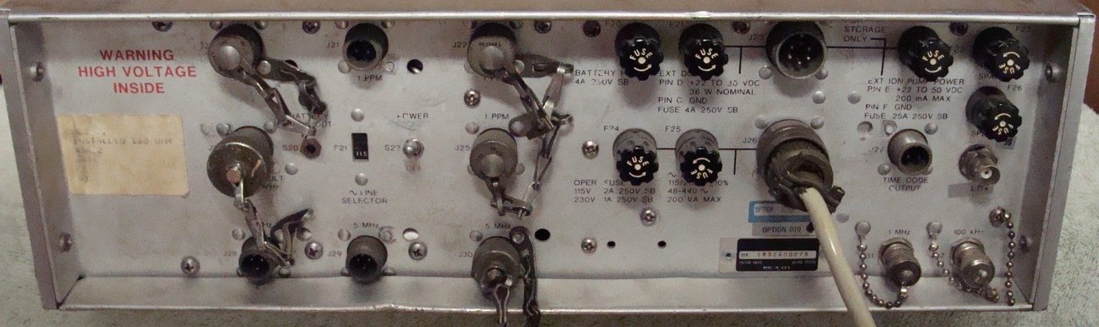 |
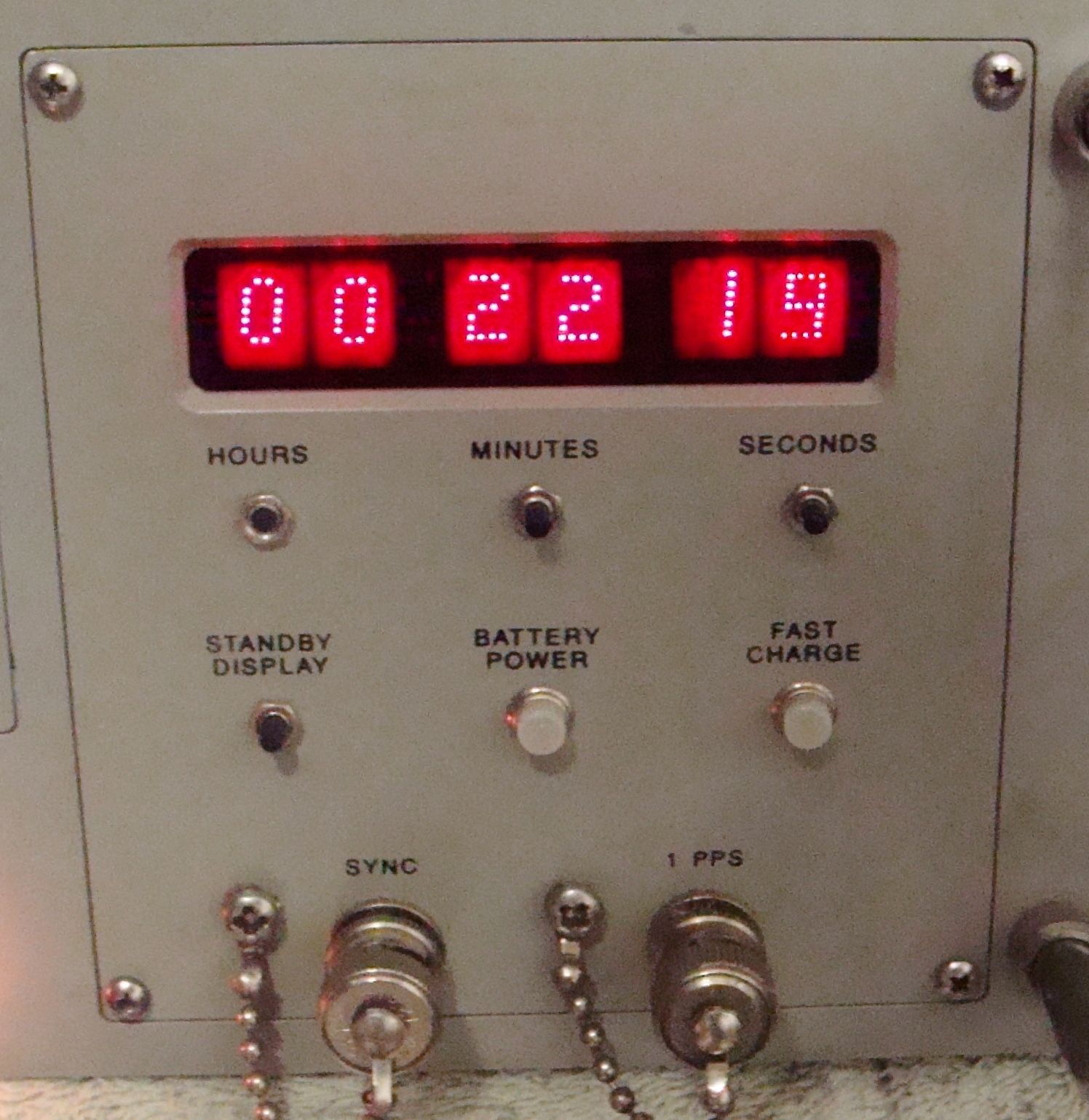
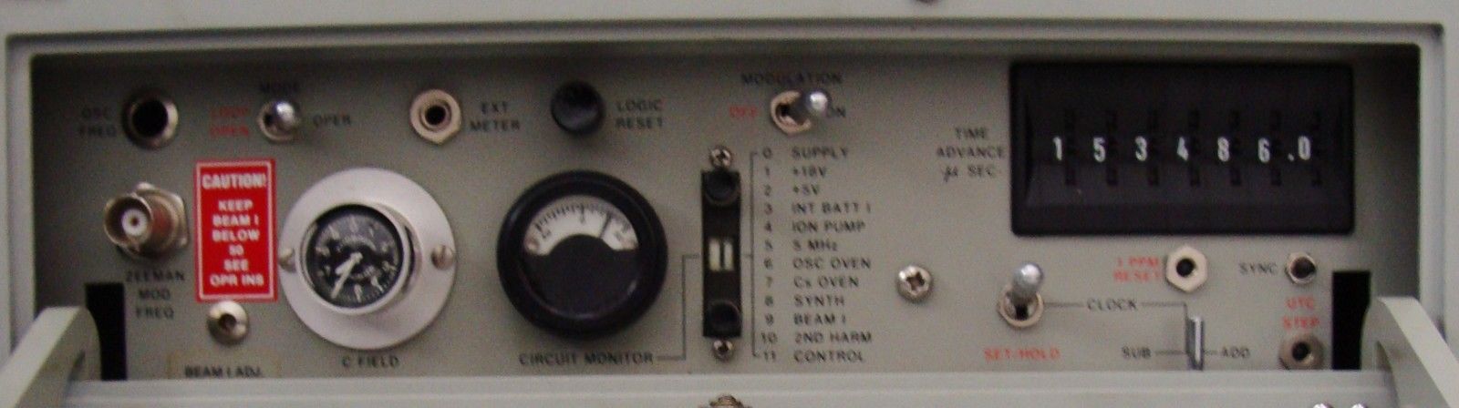
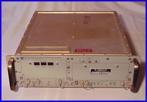
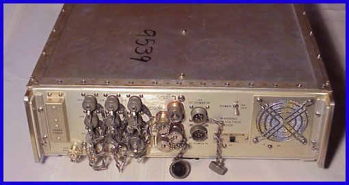
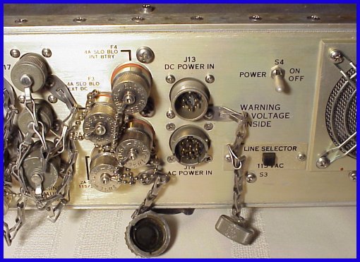
| O-1824A/U Cesium Beam Standard
Frequency Electronics Inc. FE-5440A
|
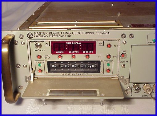
|
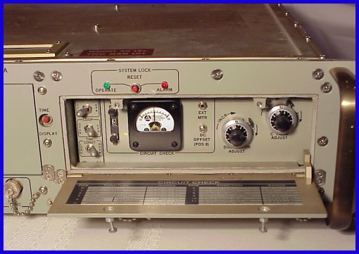
|
Data sheet & info |
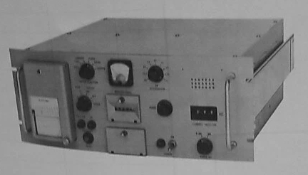
AN/URM-115 Frequency Standard Deviation Meter
|
||
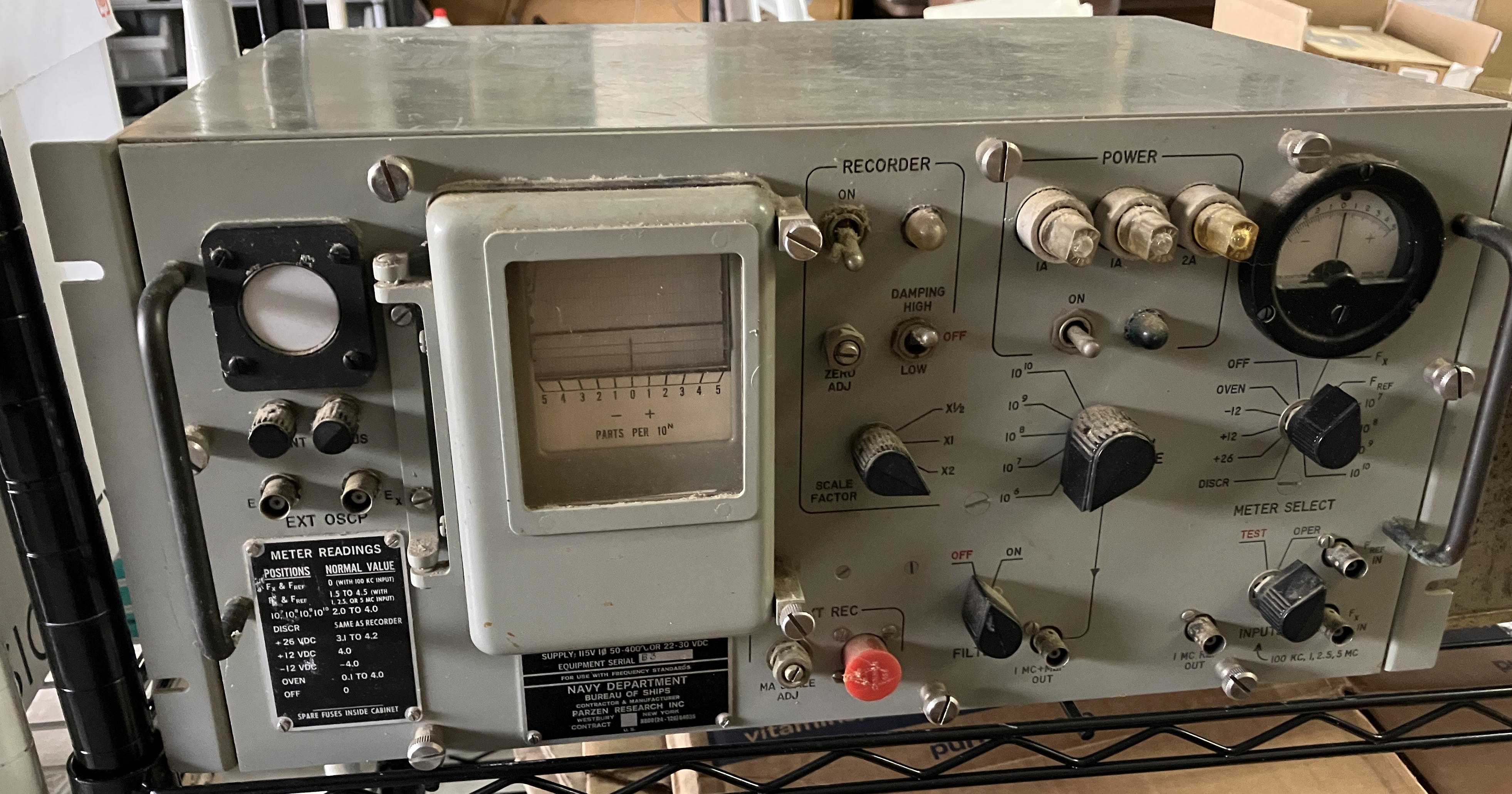
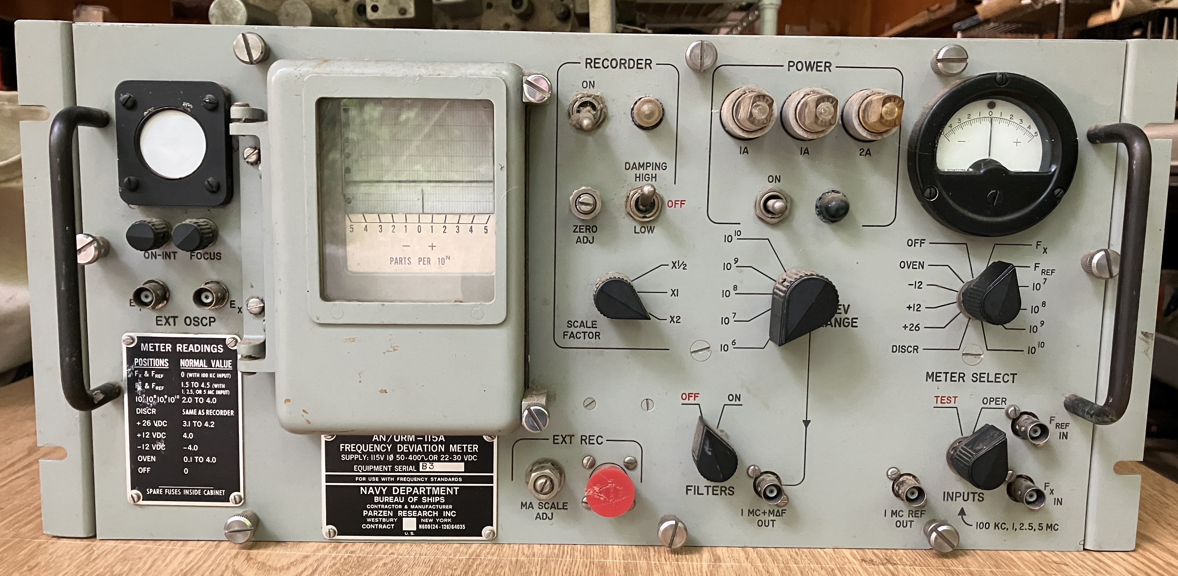
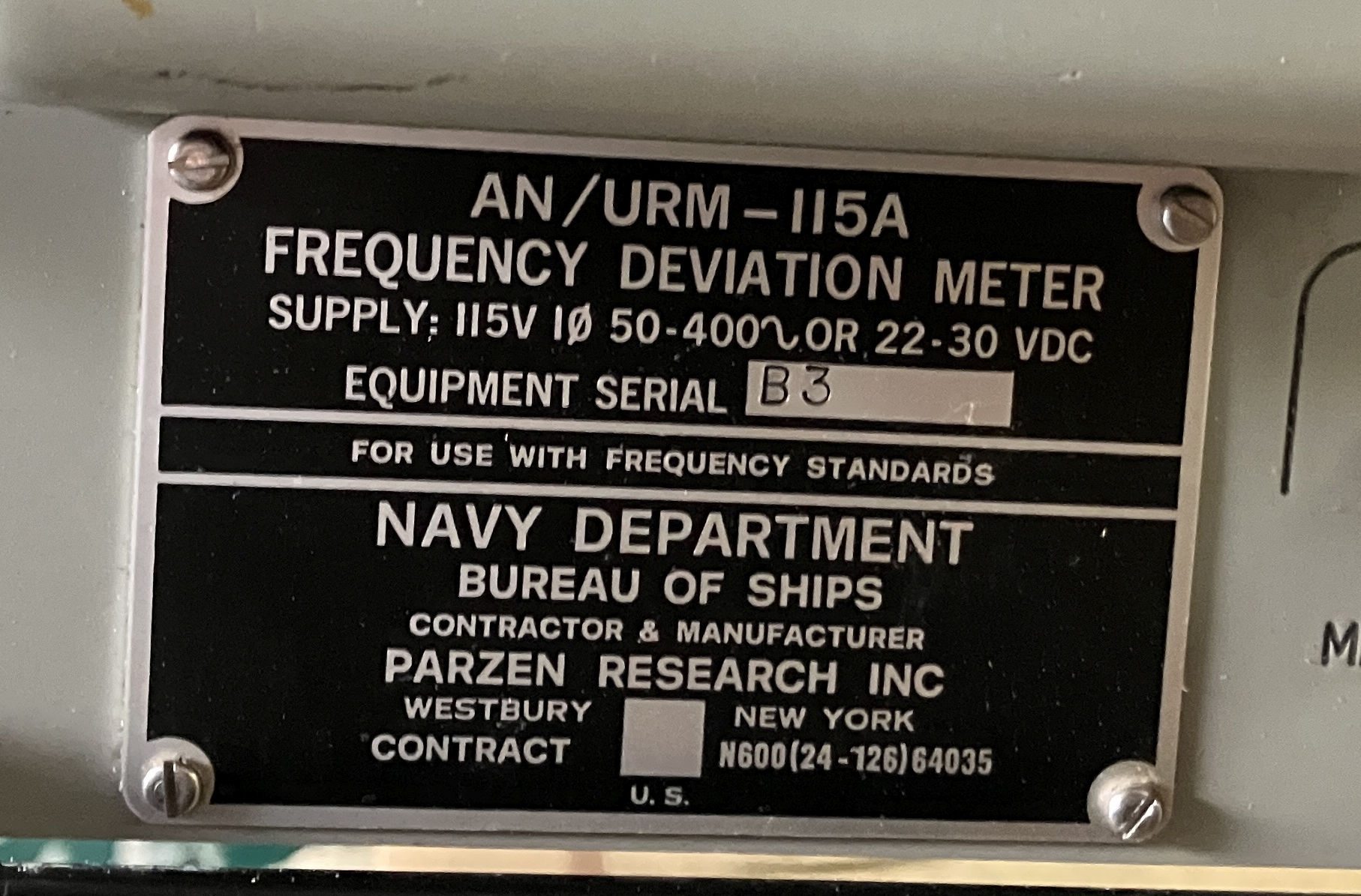
AN/URM-115A Frequency Standard Deviation Meter
|
||
 |
 |
 |
R-1407/URQ Receiver-Comparator |
|
== |
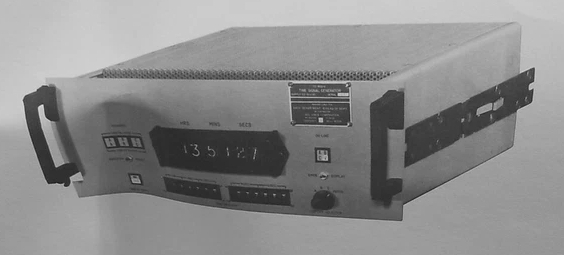
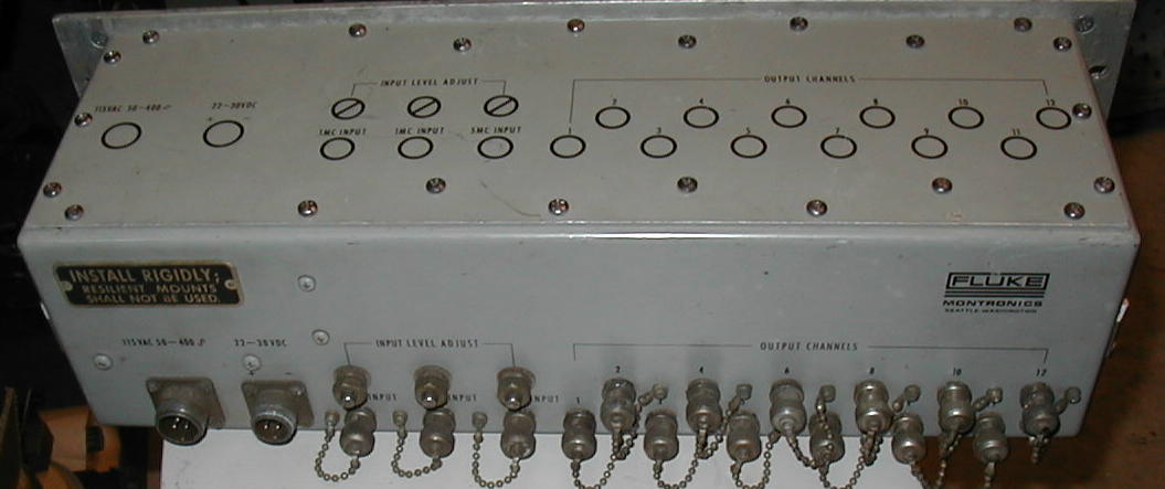
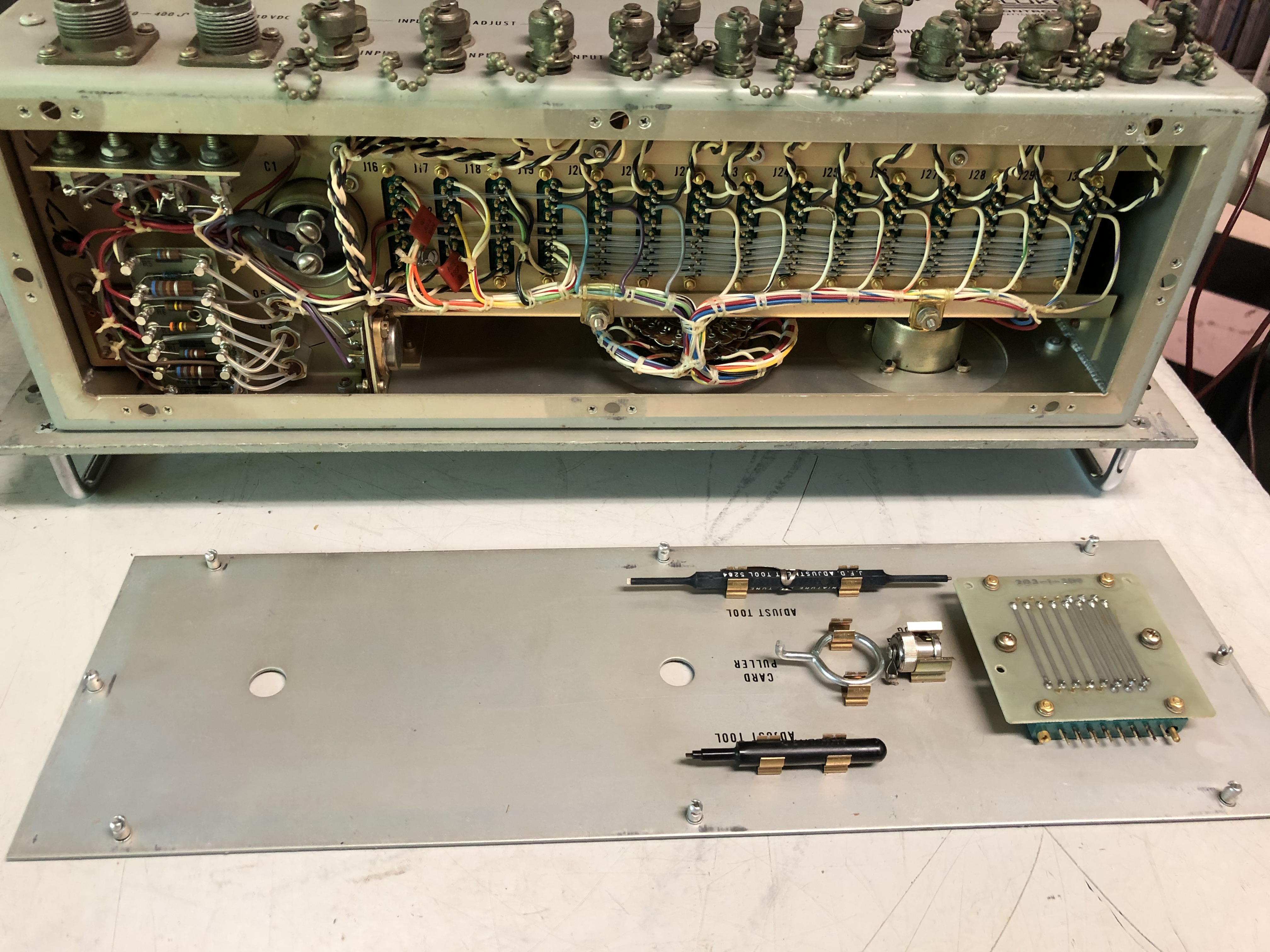
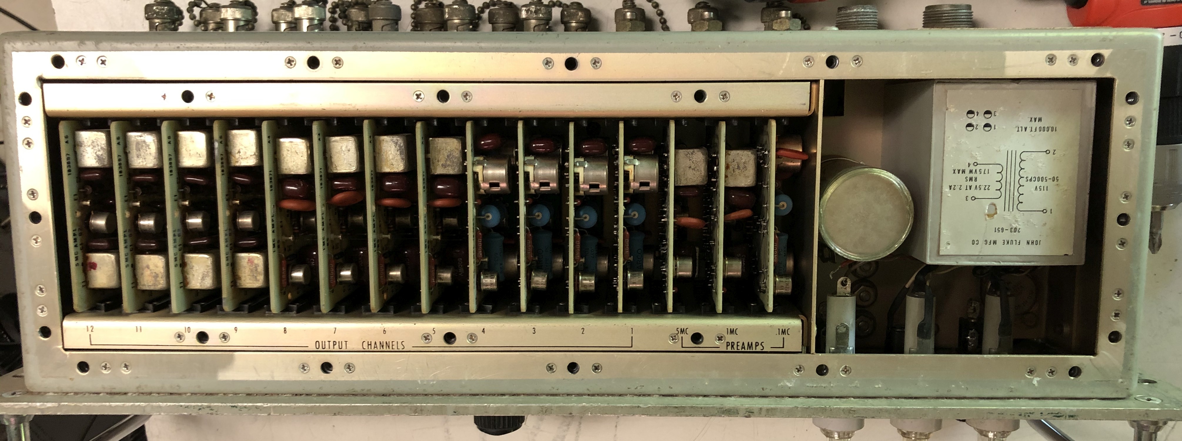
TD-810/U Time Signal Generator |
|
== |
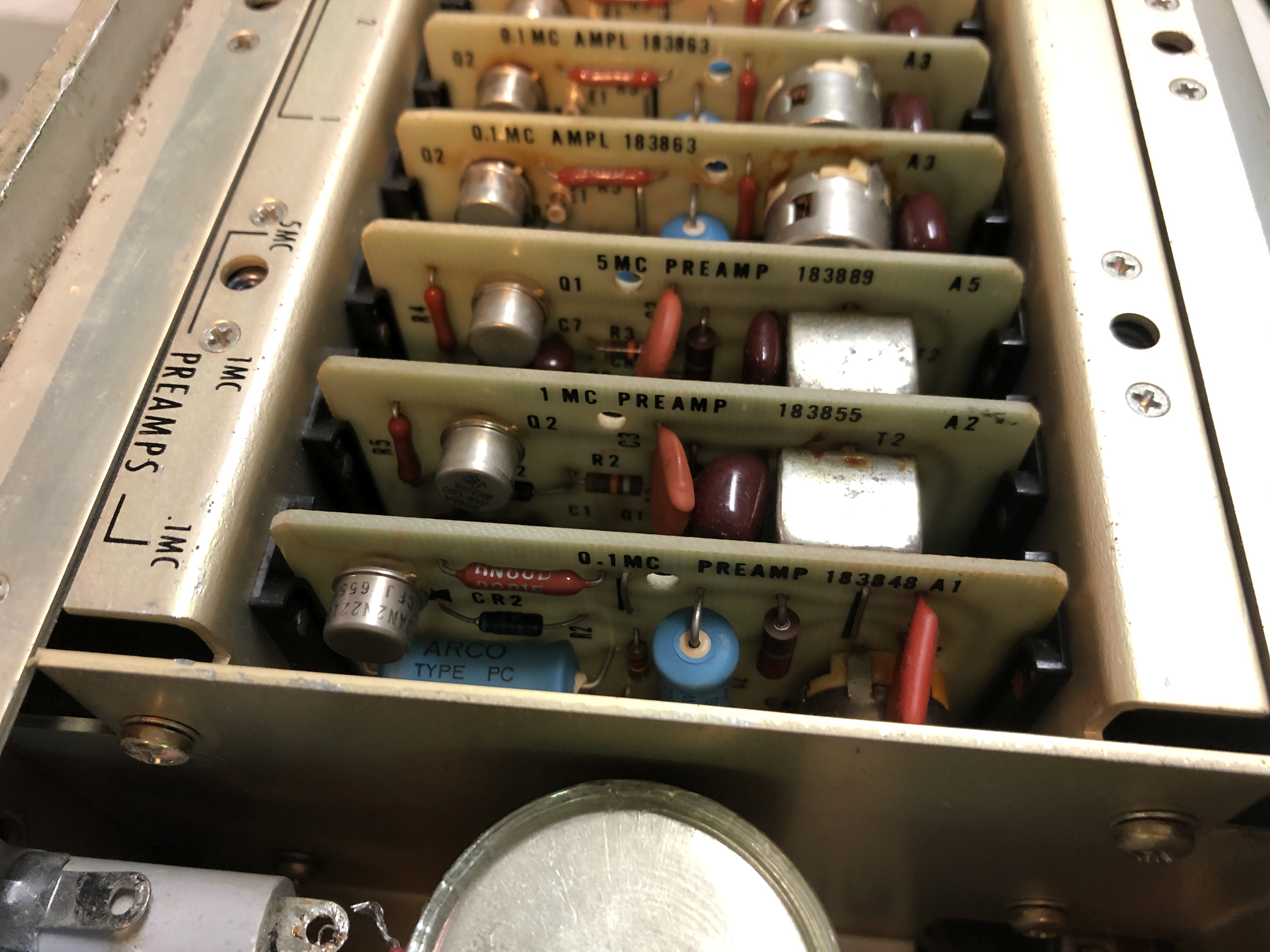
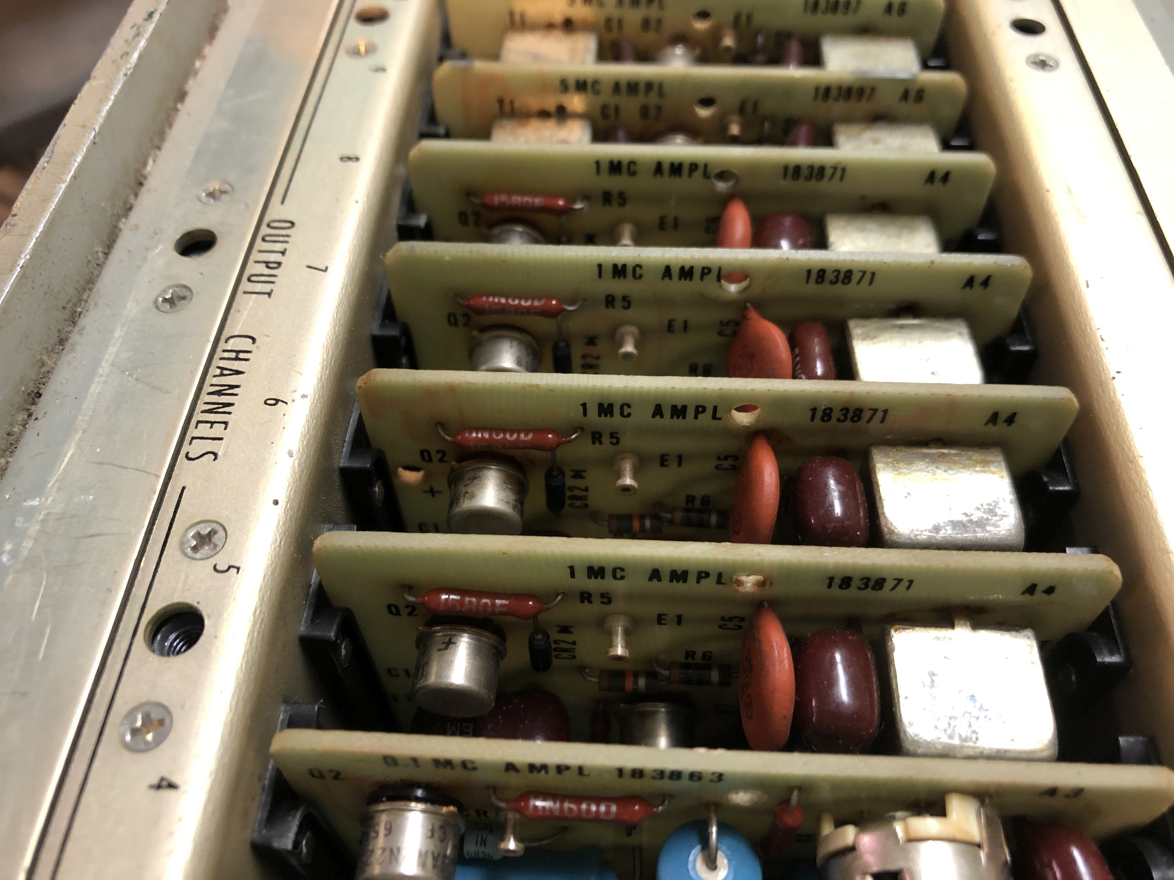
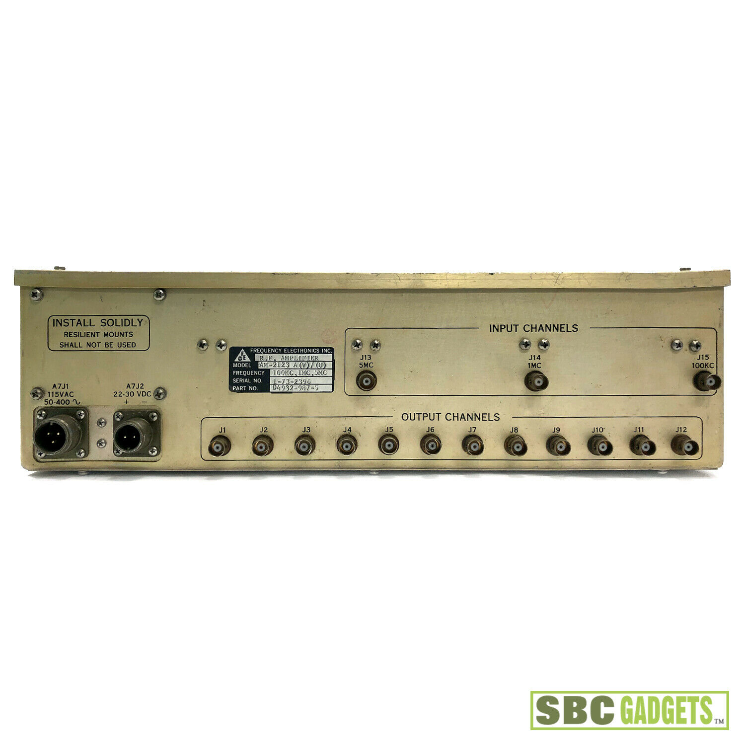
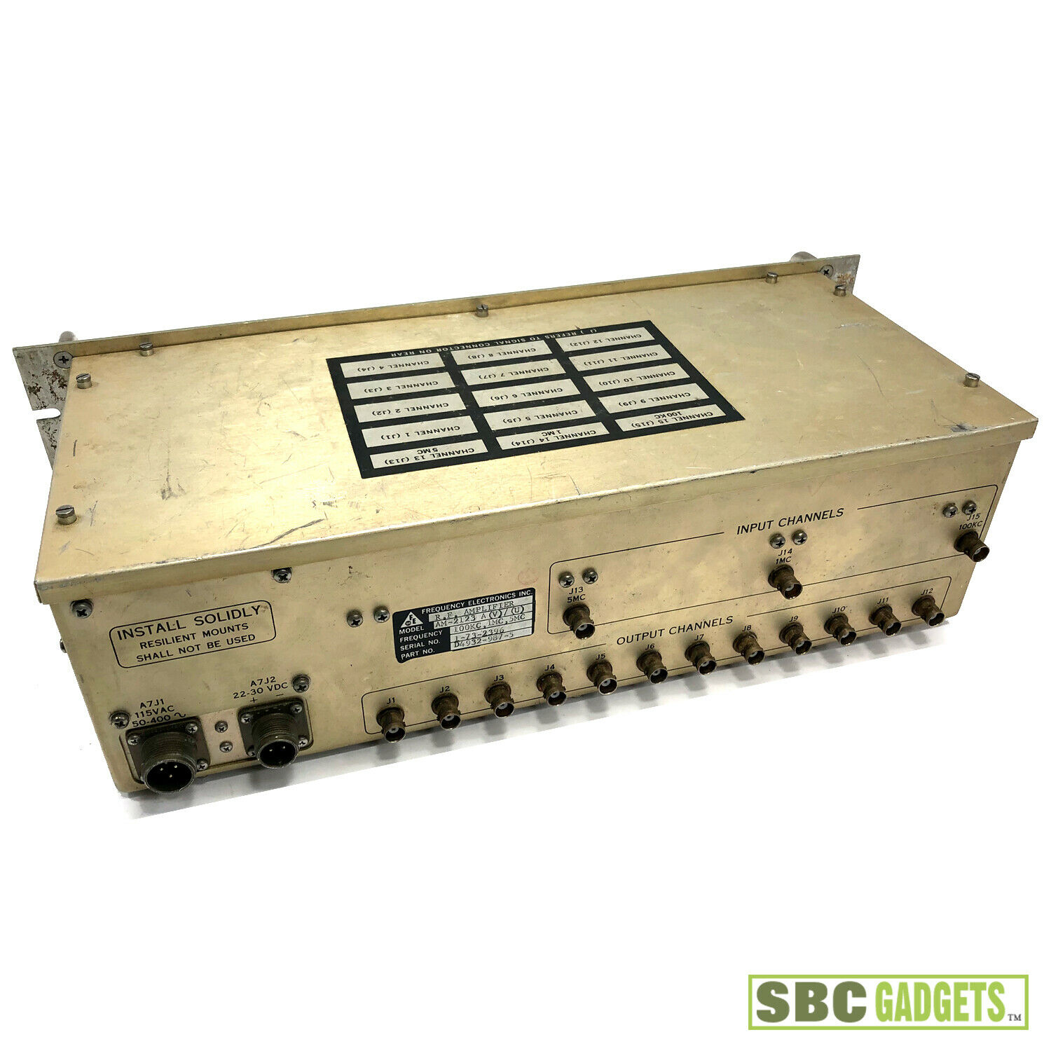
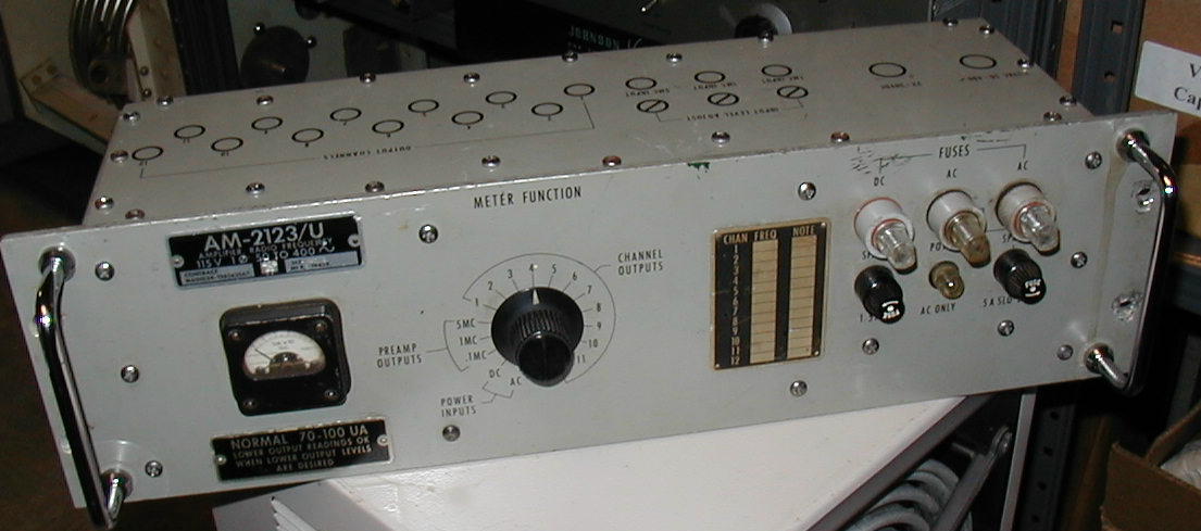
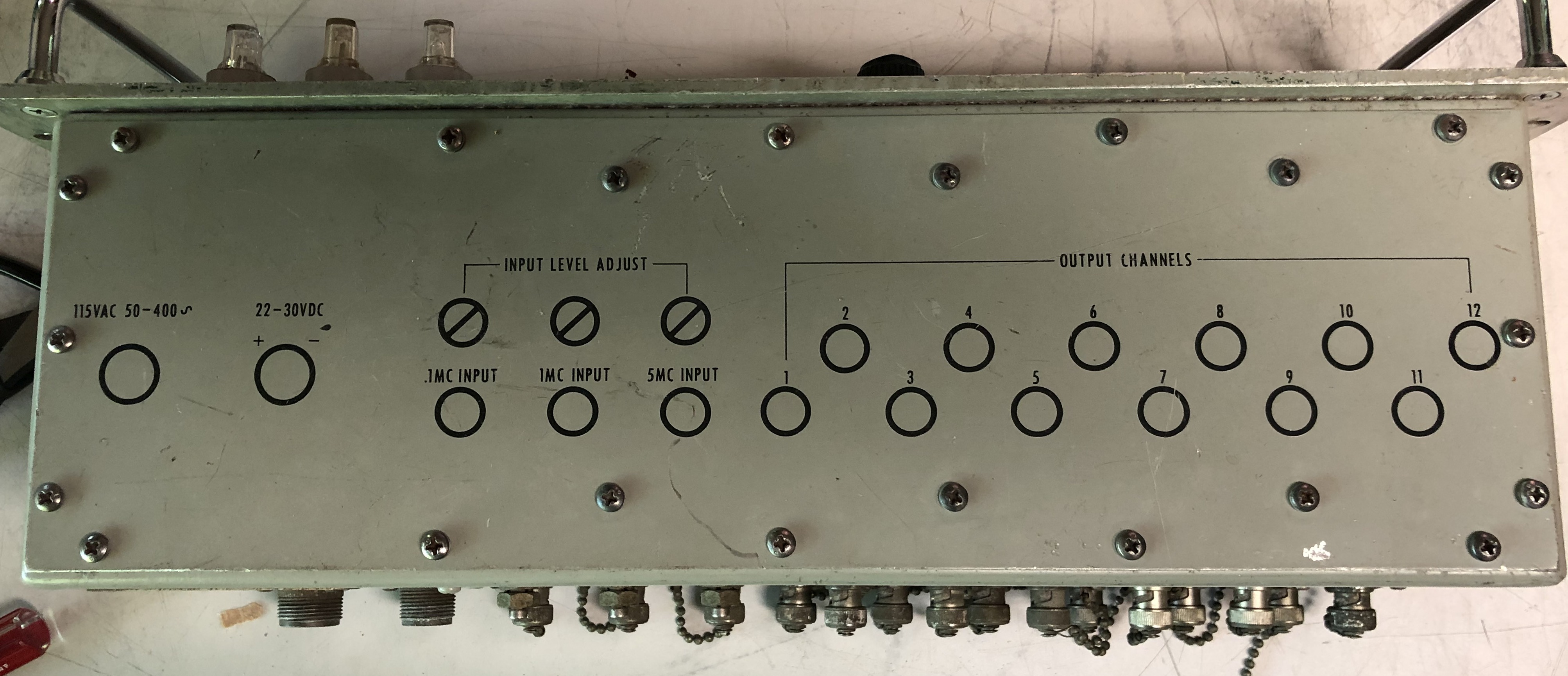
AM-2123/U
|
|

|
specifications here
|
 |
 |
== | == |
 |
 |
|
 |
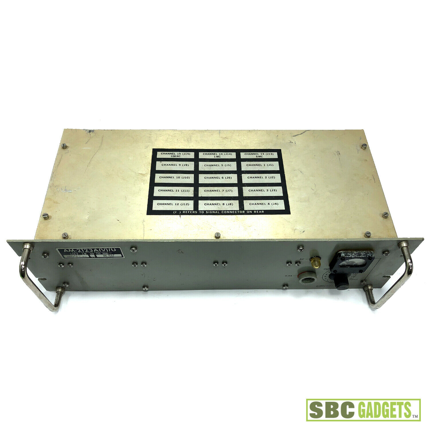
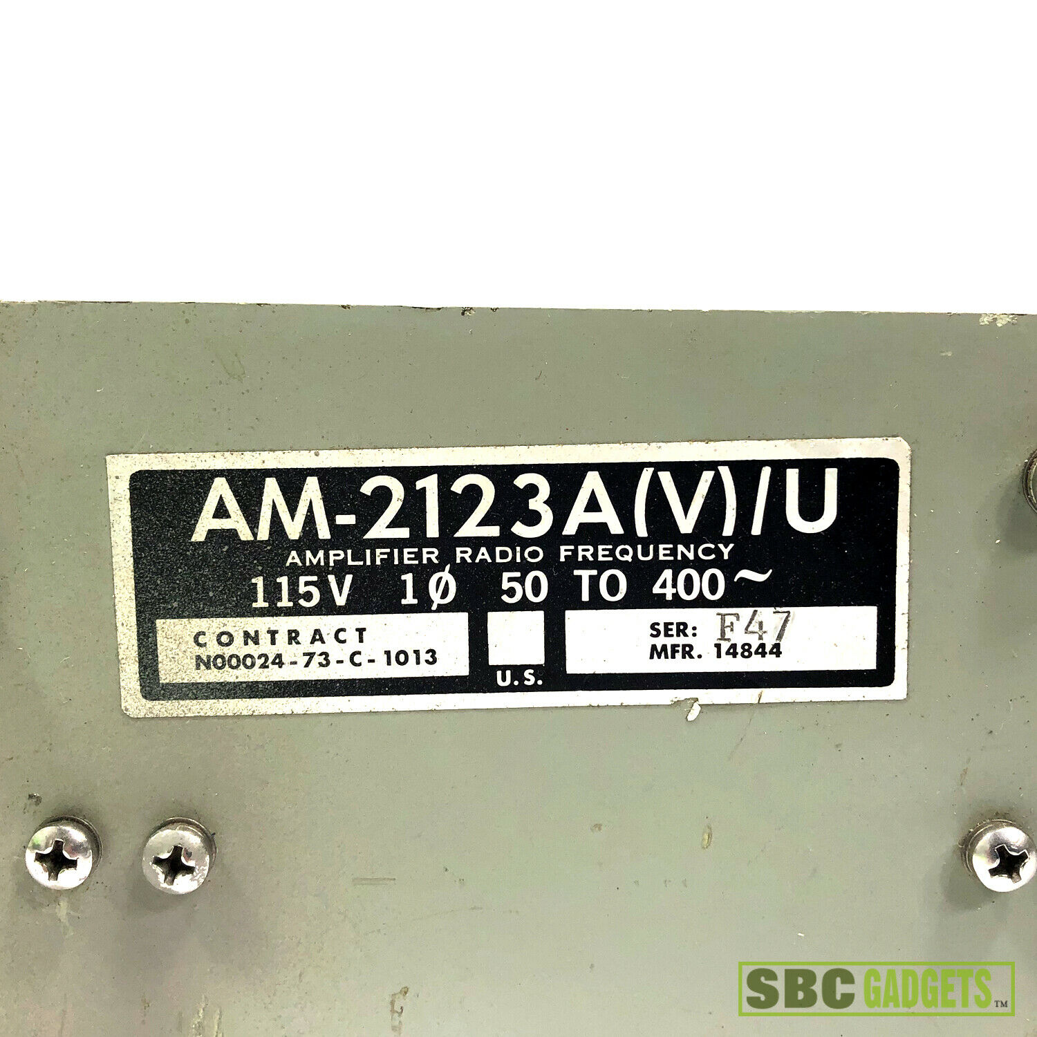
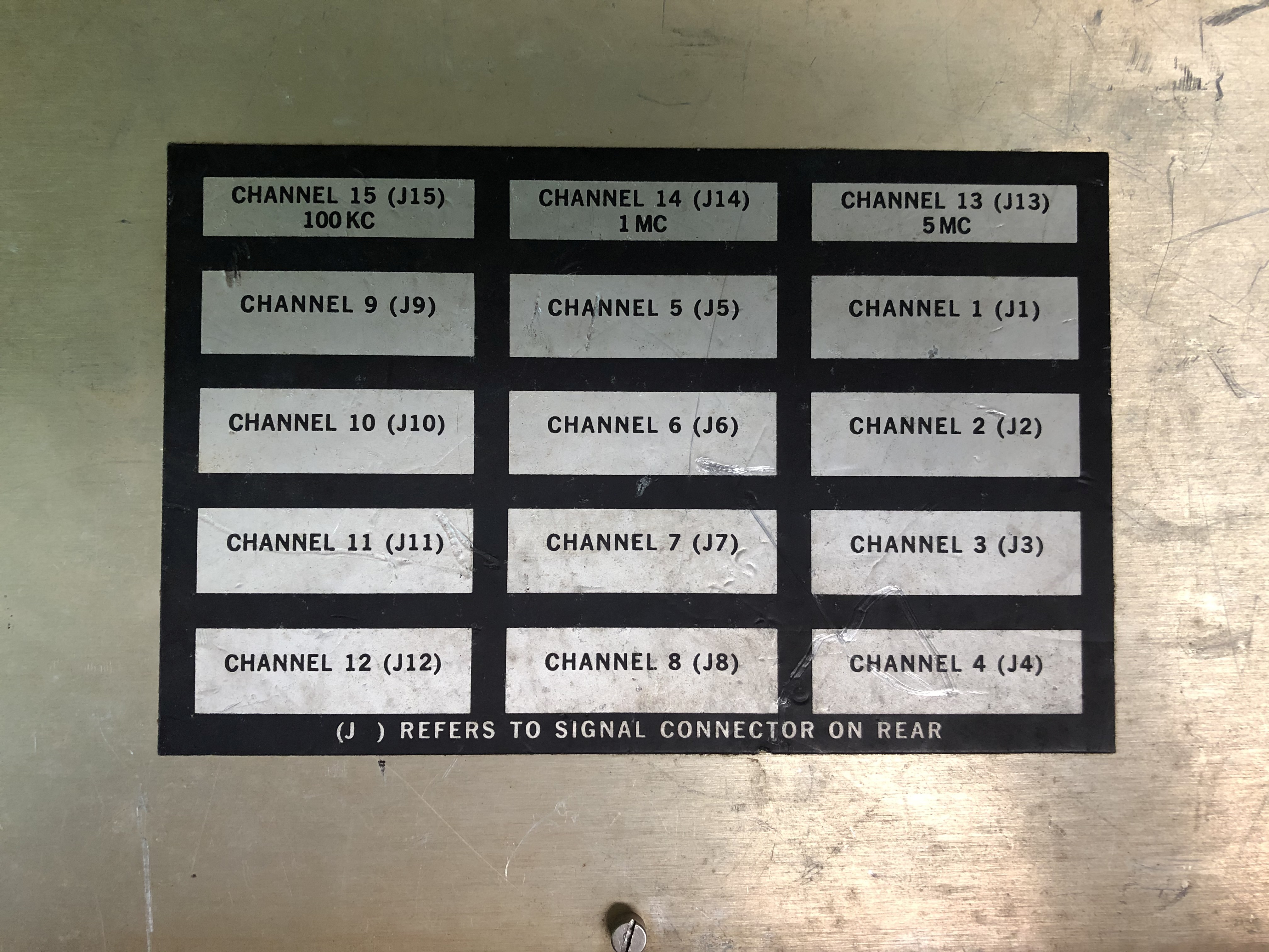
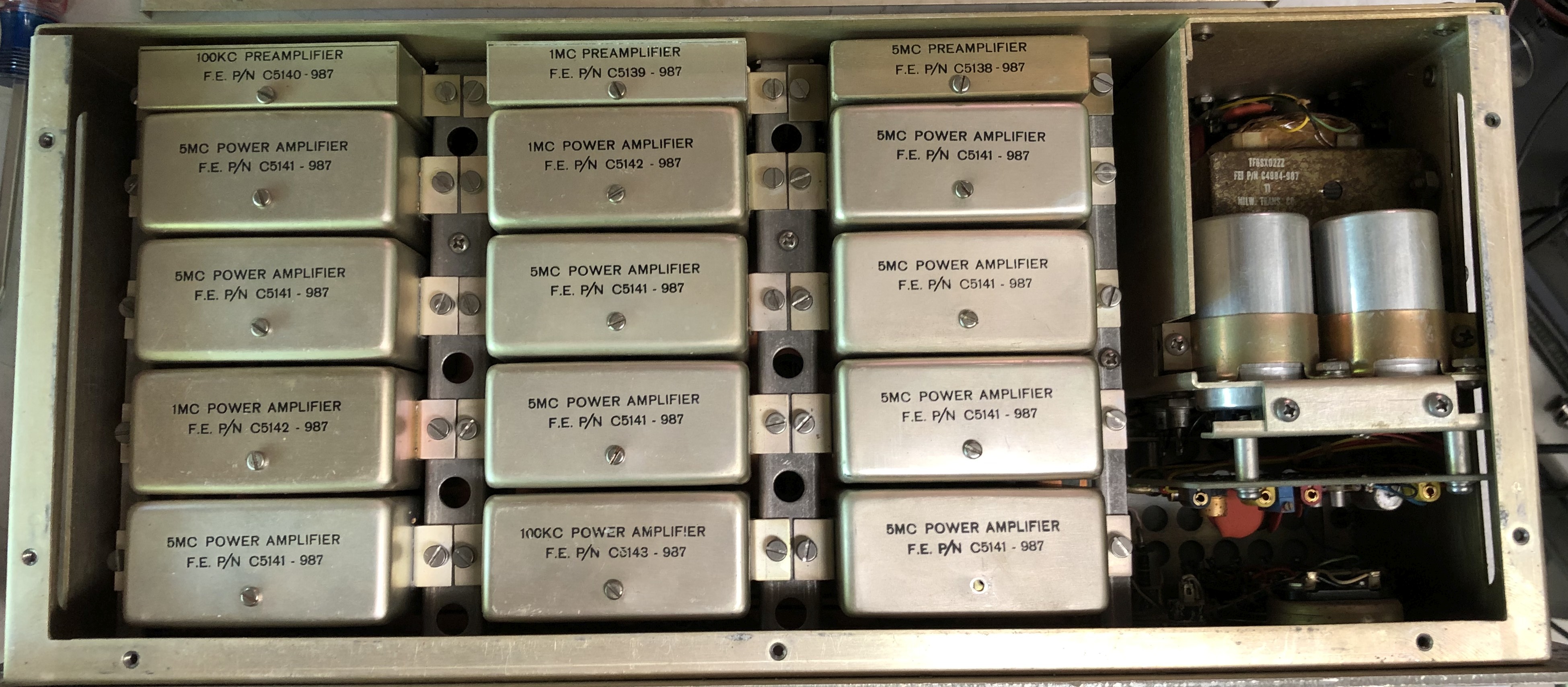
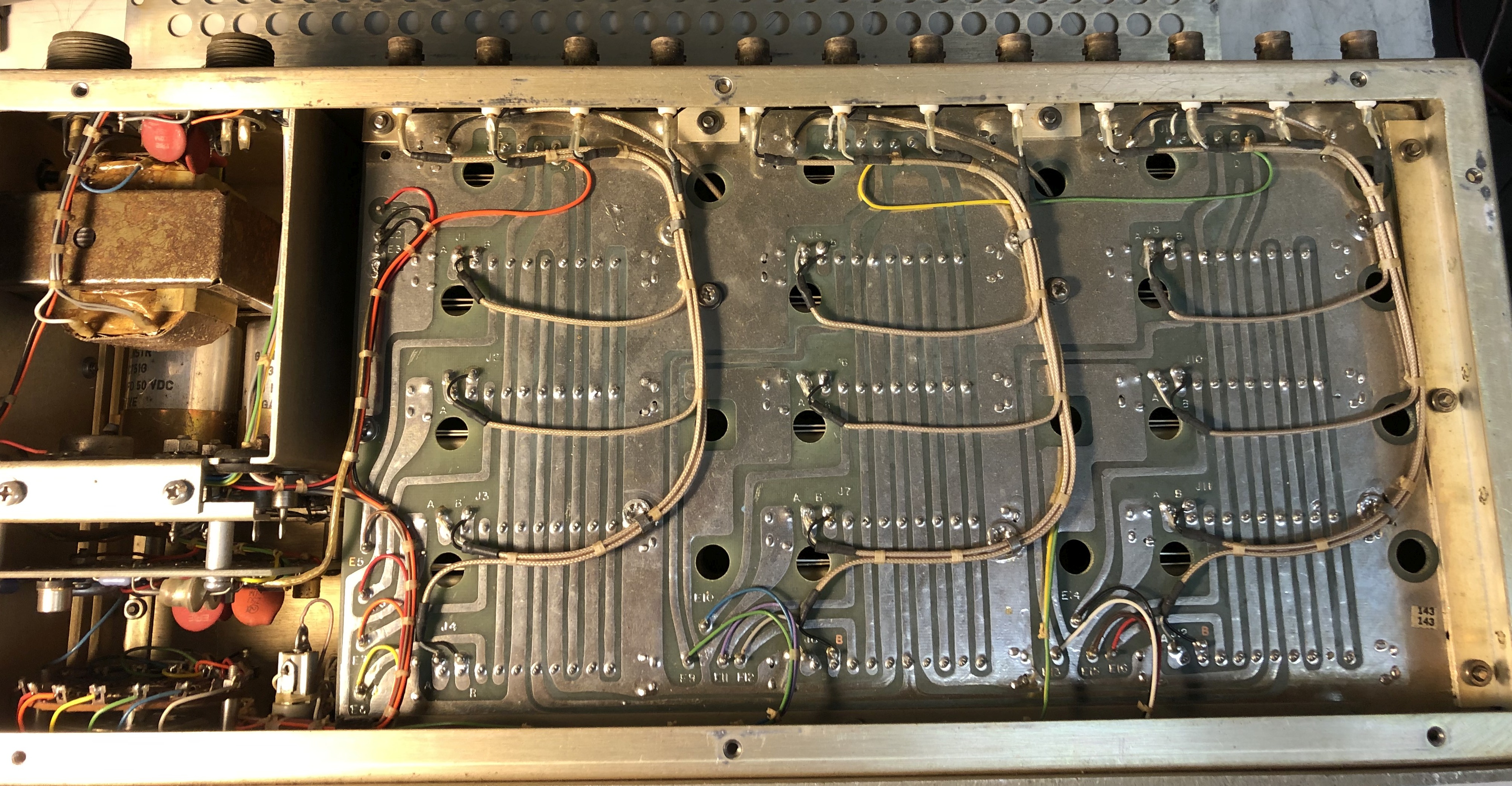
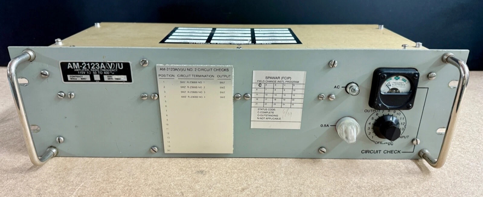
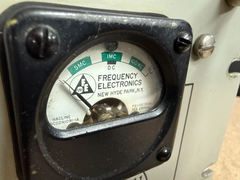
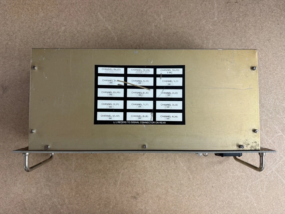
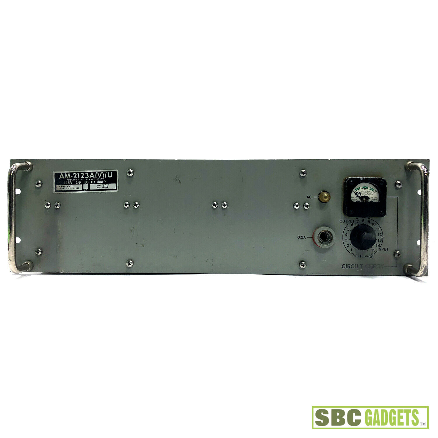
AM-2123A/U
|
 |
|
 |
 |
 |
|
 |
 |
 |
== | == |
 |
 |
|
 |
 |
 |
|
 |
 |
 |
|
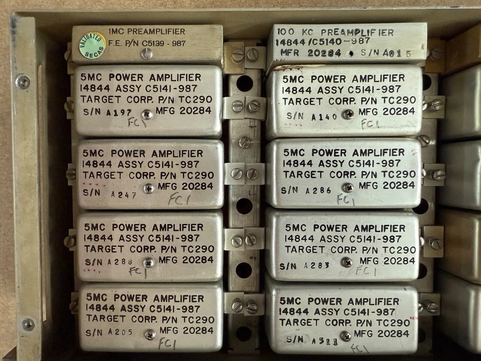
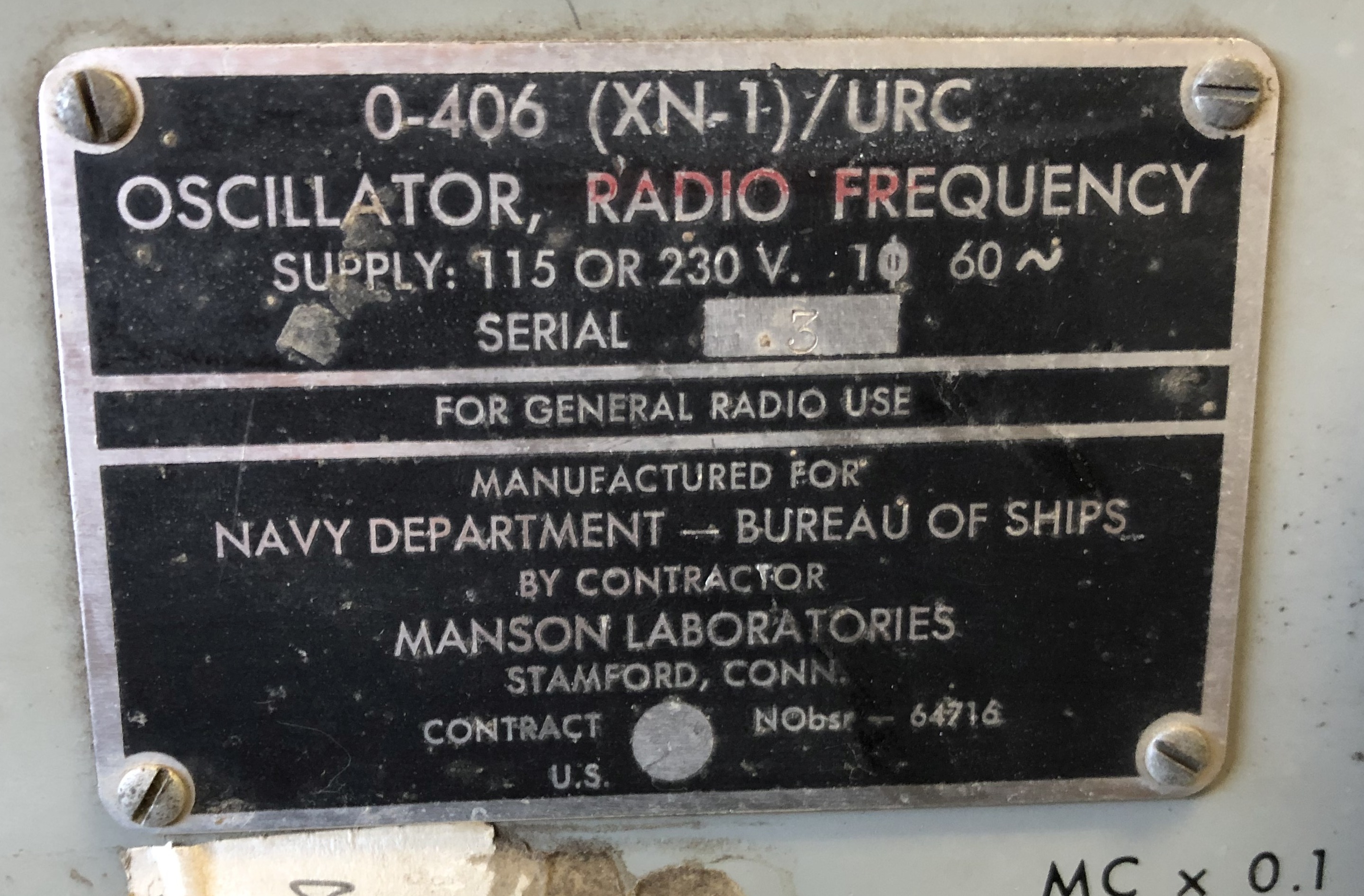
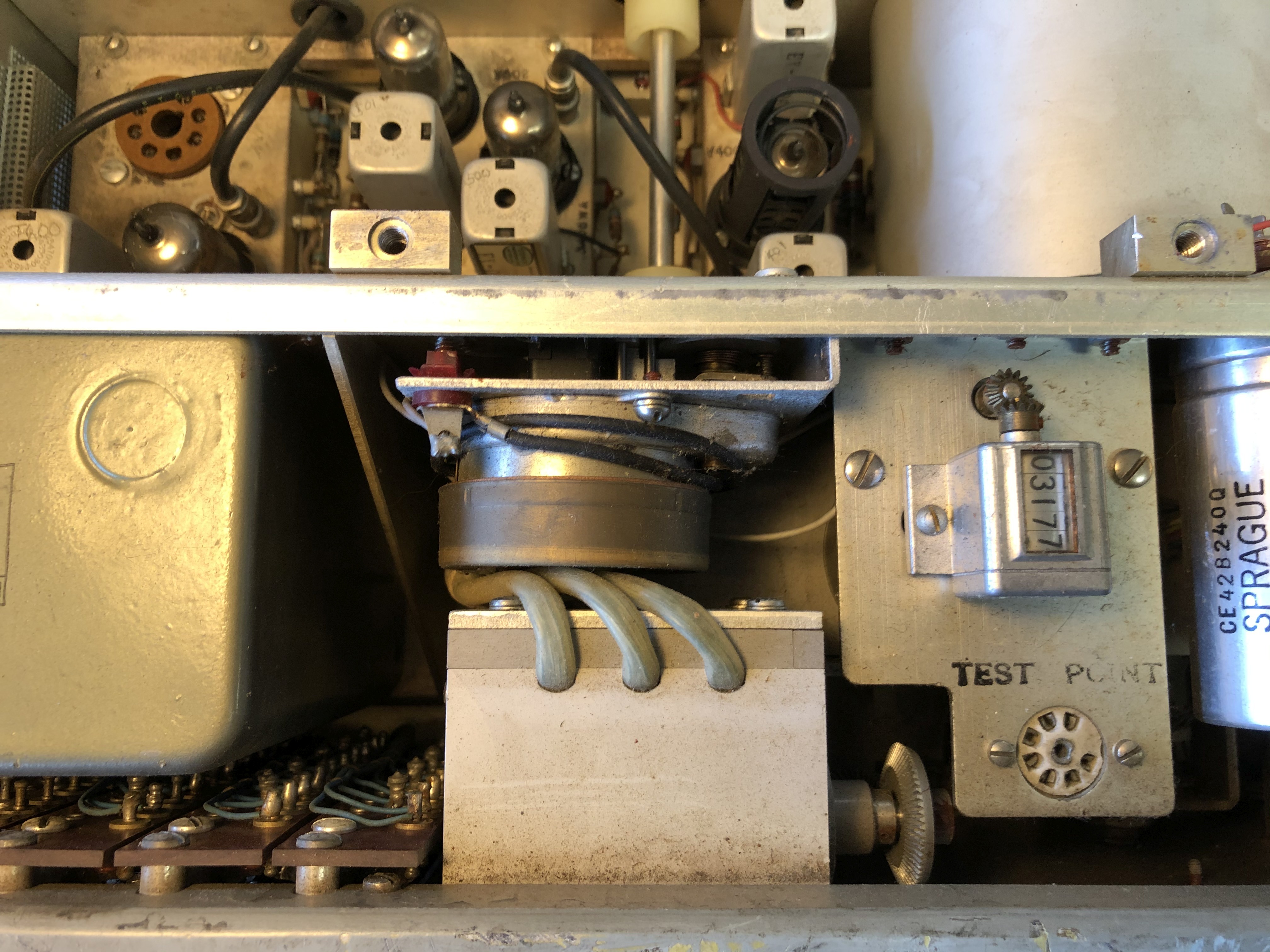
== |
| O-406(XN-1)/URC (225-400 MC) (VFO for TED and URT-7 transmitters) prototype - Manson Labs I need a manual and/or any info! Please send email if you can help. |
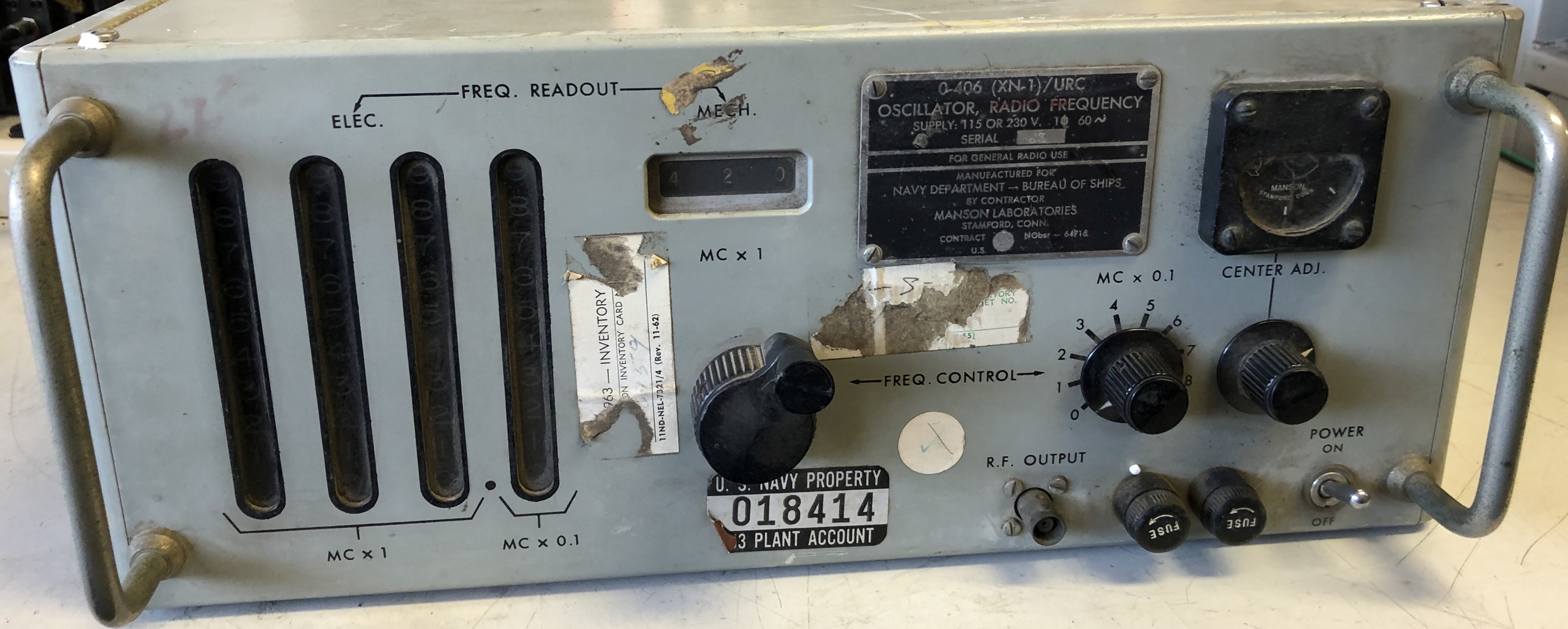
O-466/SRC is a miniaturized version |
 |
 |
 |
 |
 |
 |
 |
 |
 |
 |
| O-463/SRC | need photo | RF synthesizer
need more info |
Navships 93151 |
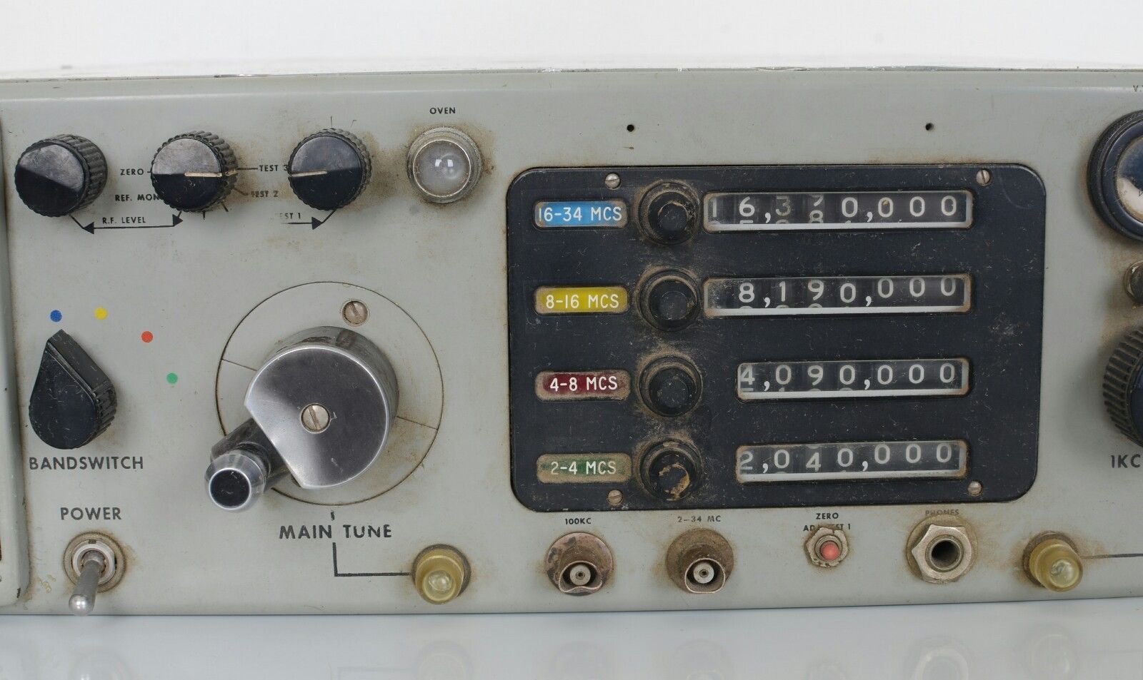
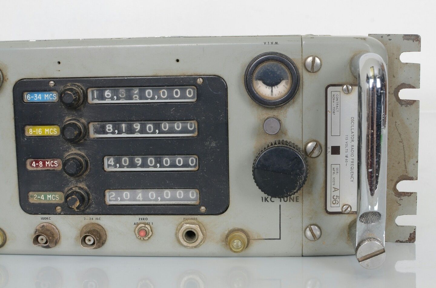
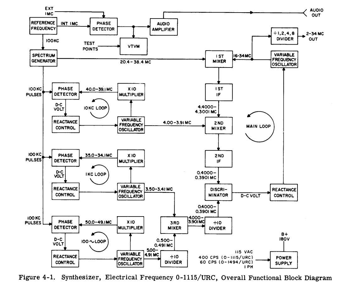
| O-464/SRC
O-792/SRC is the 400 cps version BuShips Journal article - Development of Frequency Synthesizers
|
Provides more than 64,000 frequencies in the range of 2 to
34 mc, covered in four bands. Auxiliary outputs of 1 mc and 100 kc are
also provided. The stability of all output frequencies is 1 part in 10^8
per day.
|
|
NAVSHIPS 93463 NAVSHIPS 93797
|
|
 |
|
|
| O-1207/URC O-1207A/URC |
2-34 mc synthesizer
|
 |
O-1207 manuf by Manson Lab. Instruction Book download pdf O-1207A manuf by Oklahoma Aerotronics Photos thanks to David Dragoni |
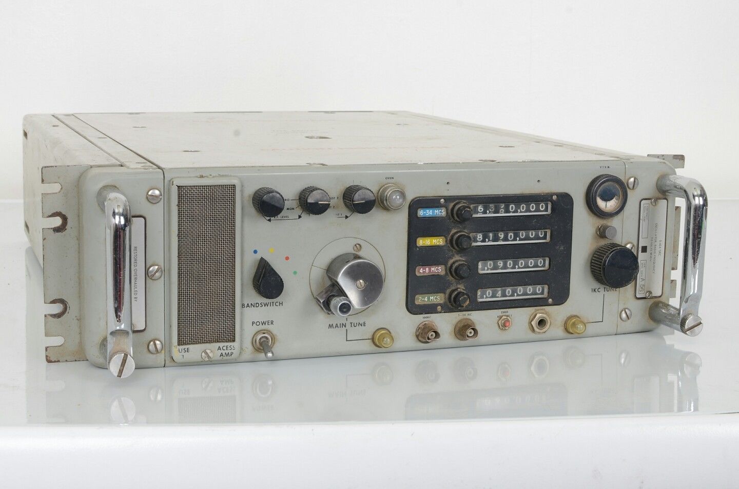
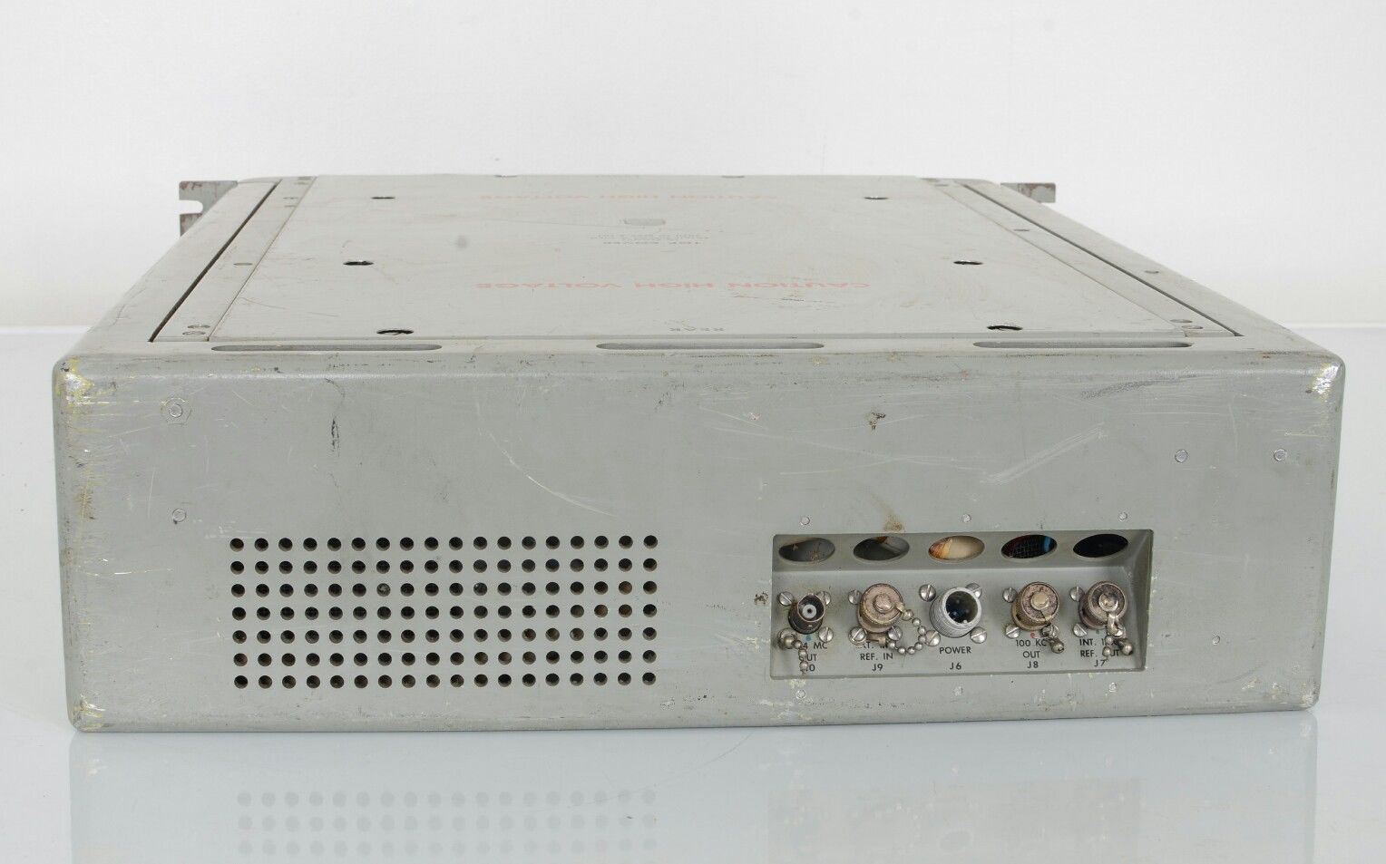
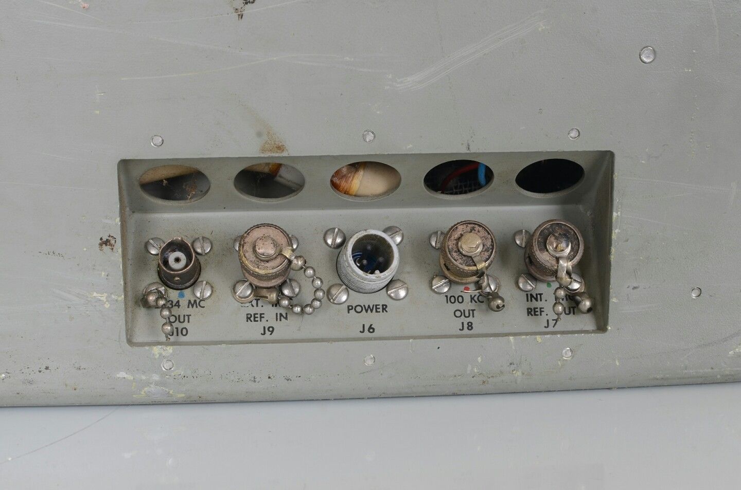
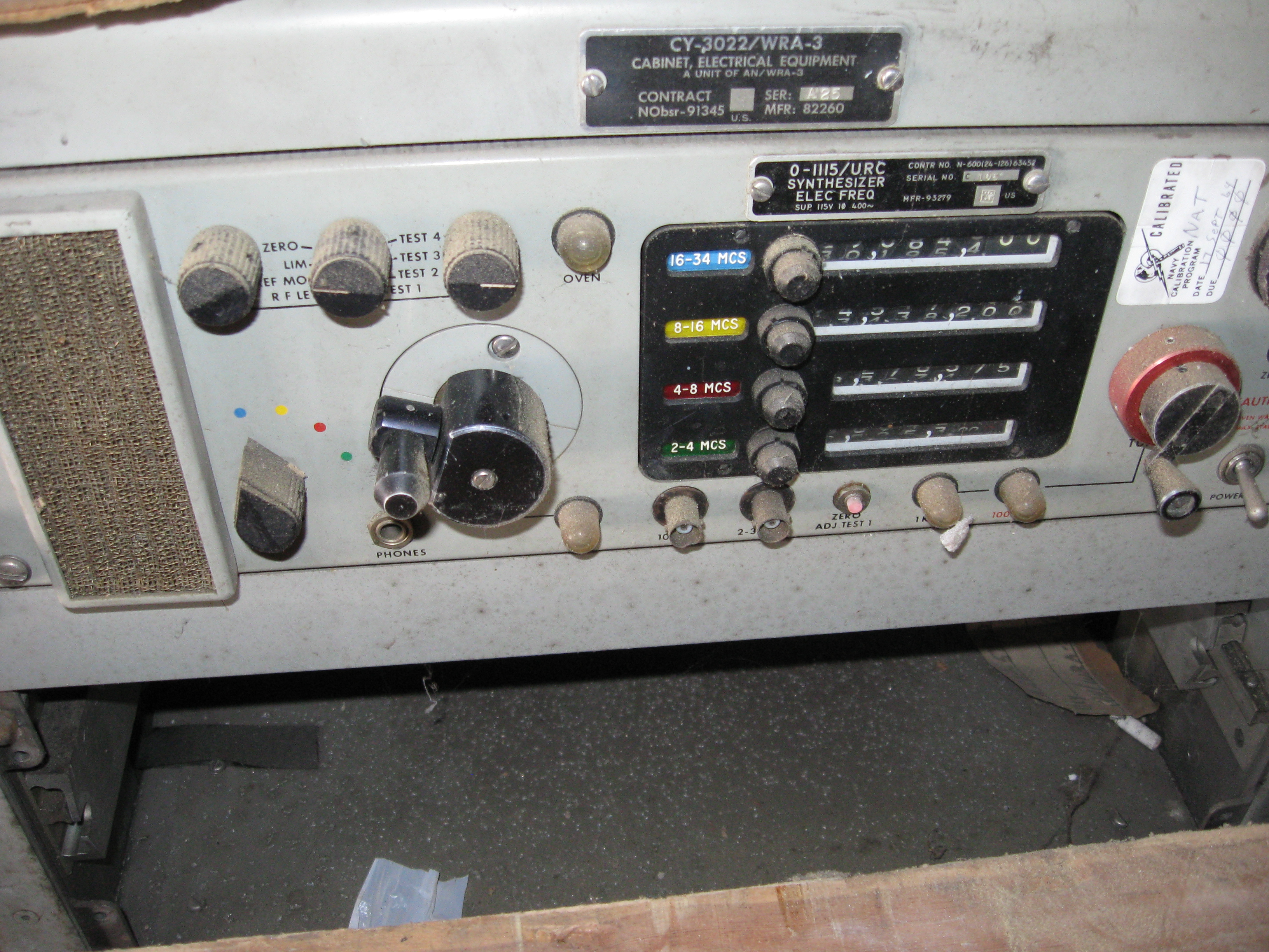
| O-1494/URC
O-1115/URC is the 400 cps version |
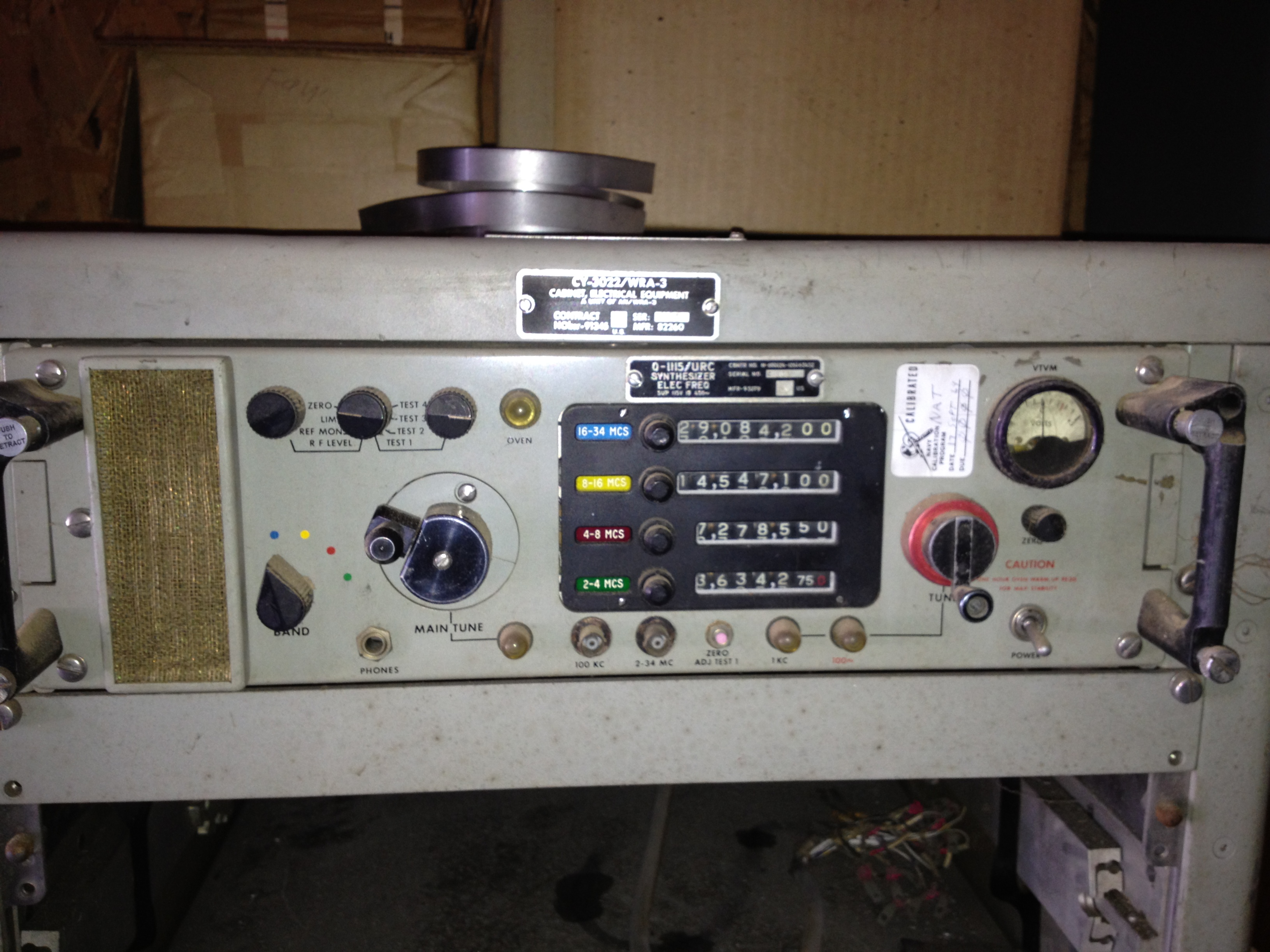
need better photo |
2-34 mc synthesizer
|
Hallicrafters NAVSHIPS 0969-256-6010 |
| O-1555/URC | 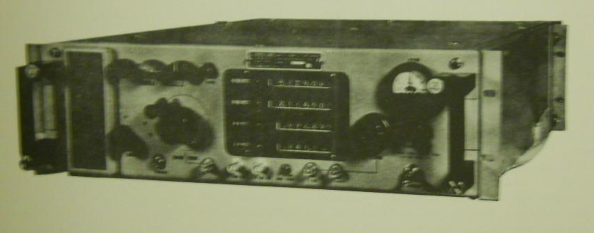 |
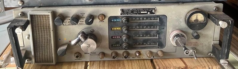 - photo thanks to WB2GCR |
NAVSHIPS 0969-126-9010 |
From "Evolution of Naval Radio-Electronics and Contributions of the Naval Research Laboratory" (Gebhard) - 25MB pdf
|
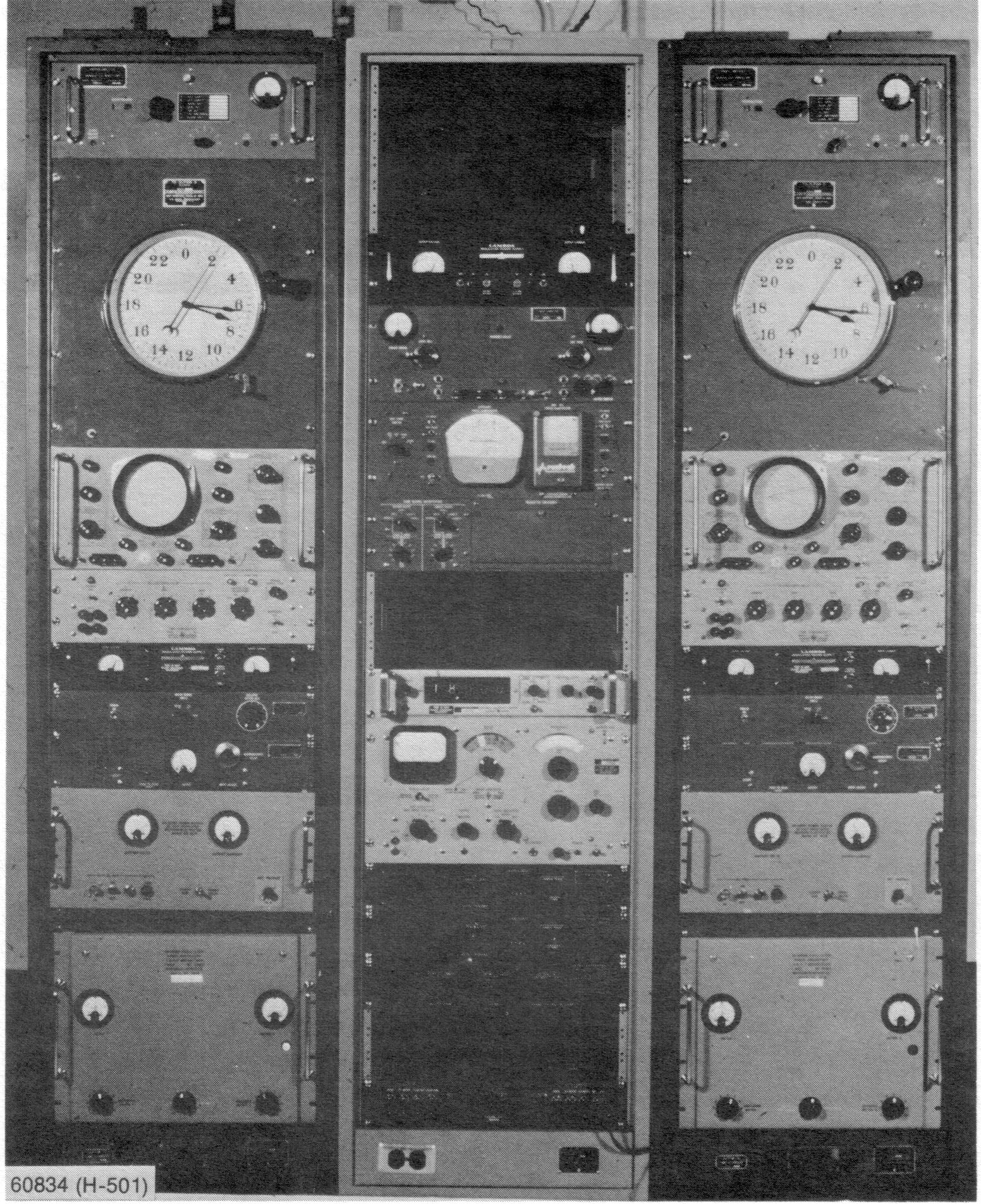
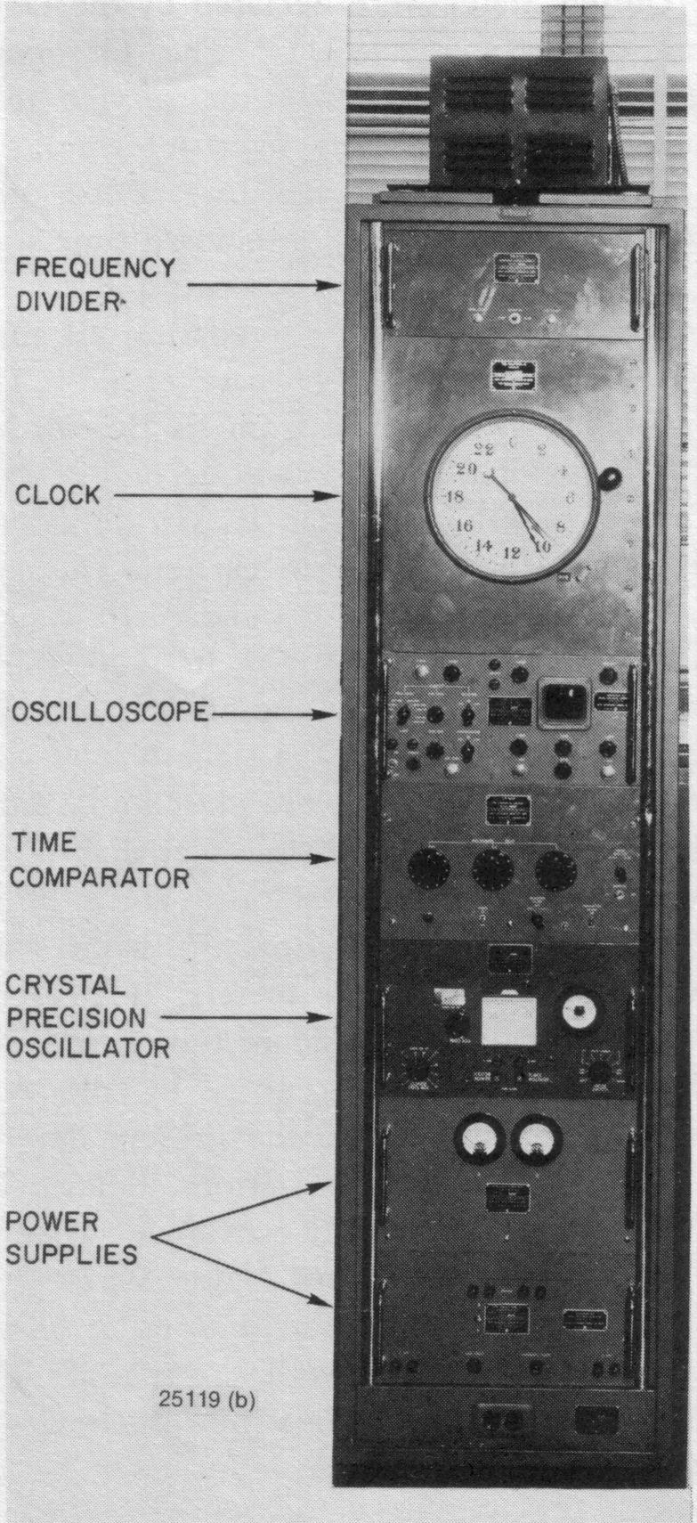
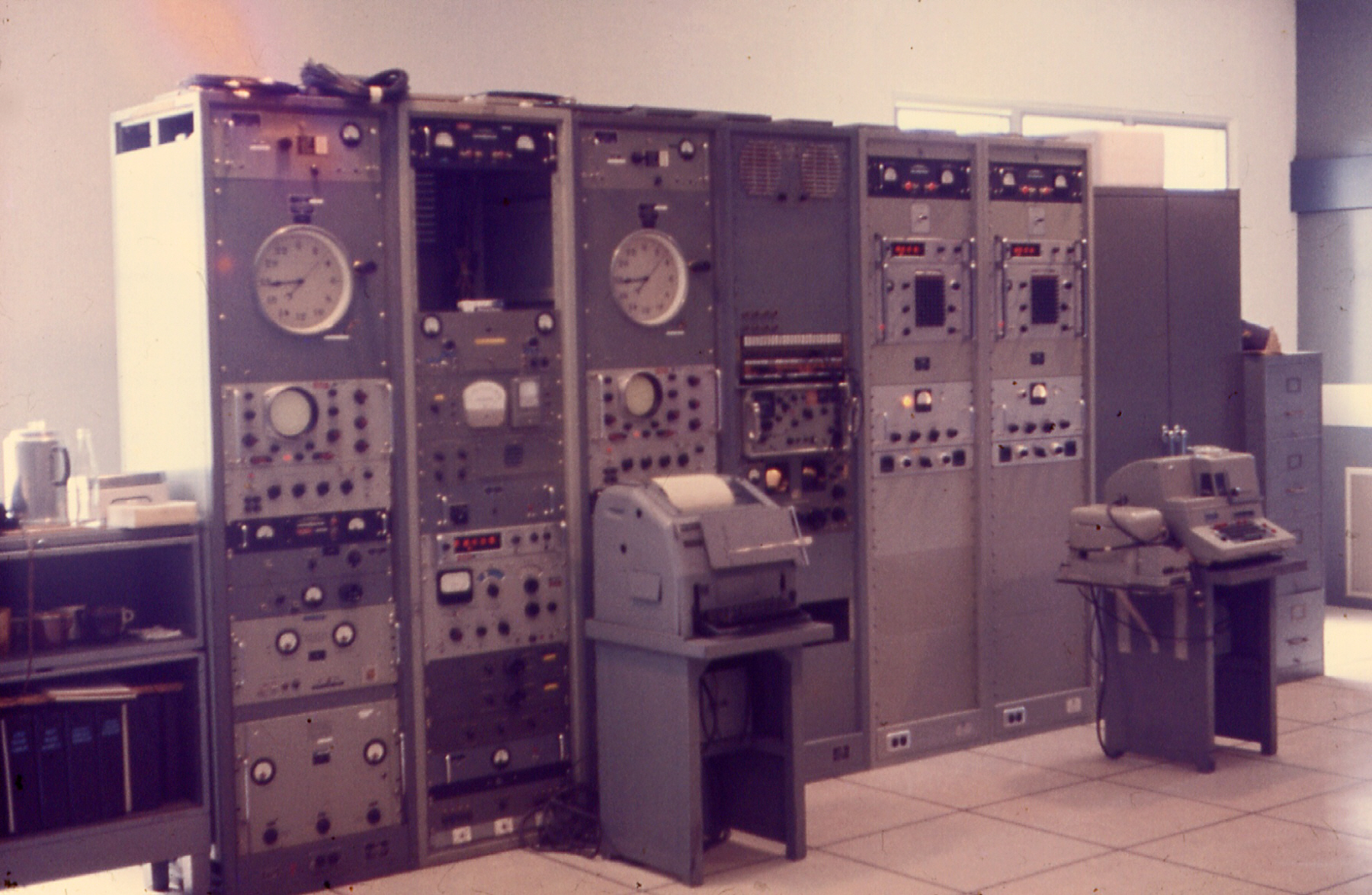
FIRST TRANSMISSIONS OF HIGHLY PRECISE FREQUENCY AND TIME ON VLF NRL was first to devise techniques for the transmission of precise frequency and time by VLF and to apply these techniques, thereby obtaining a two-order increase in accuracy (or to 2 parts in 1010) in frequency and a five-fold increase in the accuracy of time (or to 200 microseconds) over that previously possible with transmissions in the high-frequency band. NRL first applied the techniques to the Navy's station NBA at Summit, Panama Canal Zone (1959). Shown is the NBA frequency-time control equipment. The two similar outer panels contain time comparators immediately below the clocks. The VLF phase indicator and adjuster units are at the top of the center panel. NRL adapted the system for simultaneous FSK operations in 1963 and for timed FSK transmission operations in 1970. The frequency-comparison precision has now been improved to one part in 1012 and time accuracy to 50 microseconds. NRL's developments have been applied to the Navy's high-power VLF radio stations, providing worldwide frequency and time service in addition to their communication function. |
||
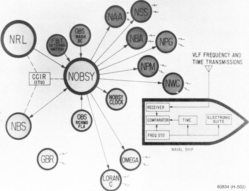 |
WORLDWIDE VLF FREQUENCY AND TIME SYSTEM
NRL's precise frequency and time developments have been applied to the Navy's high-power VLF communication stations (NAA, NSS, NBA, NPG, NPM, NDT and NWC), making possible precise frequency and time service in addition to the communication function (1959 to 1967). England's station GBR also provides service. NRL's developments have also been applied at the Naval Observatory (NOBSY) to serve its frequency and time determination and surveillance functions. NOBSY has astronomical observation stations (OBS) at Washington, D.C., and Richmond, Florida. NRL provides NOBSY with atomic time data, over a special radio circuit, which is used in combination with data from the NOBSY clock system in the determination of standard frequency and time. The system serves all military services, other government organizations, such as the Bureau of Standards (NBS), commercial interests, and organizations of other countries. International cooperation is accomplished through the International Radio Consultative Committee (CCIR) of the International Telecommunications Union (ITU), an organization under the United Nations. |
||
 |
FREQUENCY AND TIME EQUIPMENT DEVELOPED BY NRL AND INSTALLED
AT THE NAVAL OBSERVATORY FOR USE IN CONNECTION WITH ITS FREQUENCY AND TIME
DETERMINATION AND SURVEILLANCE FUNCTIONS (1955)
Shown at the left is the NRL-developed Quartz crystal clock (AN/FSM-5A).
|
||
 |
THE NRL-DEVELOPED QUARTZ CRYSTAL CLOCK WHICH WAS INSTALLED
AT ALL NAVY TIME TRANSMITTING STATIONS PROVIDED, FOR THE FIRST TIME,
STANDARD TIME TRANSMISSION COVERAGE OF THE ATLANTIC AND PACIFIC AREAS WITH
AN ACCURACY OF ONE MILLISECOND (1953)
These clocks (AN/FSM-5A) were kept accurate through observations made and corrections furnished by the Naval Observatory. In a later version, the AN/FSM-5B, NRL provided (1954) a clock which for the first time has simultaneous outputs of both sidereal and solar mean time to an accuracy of 2 parts in 1010, eliminating the Naval Observatory's long process in comparing the several clocks used in the determination of standard time. TD-31/FSM-5 clock |
||
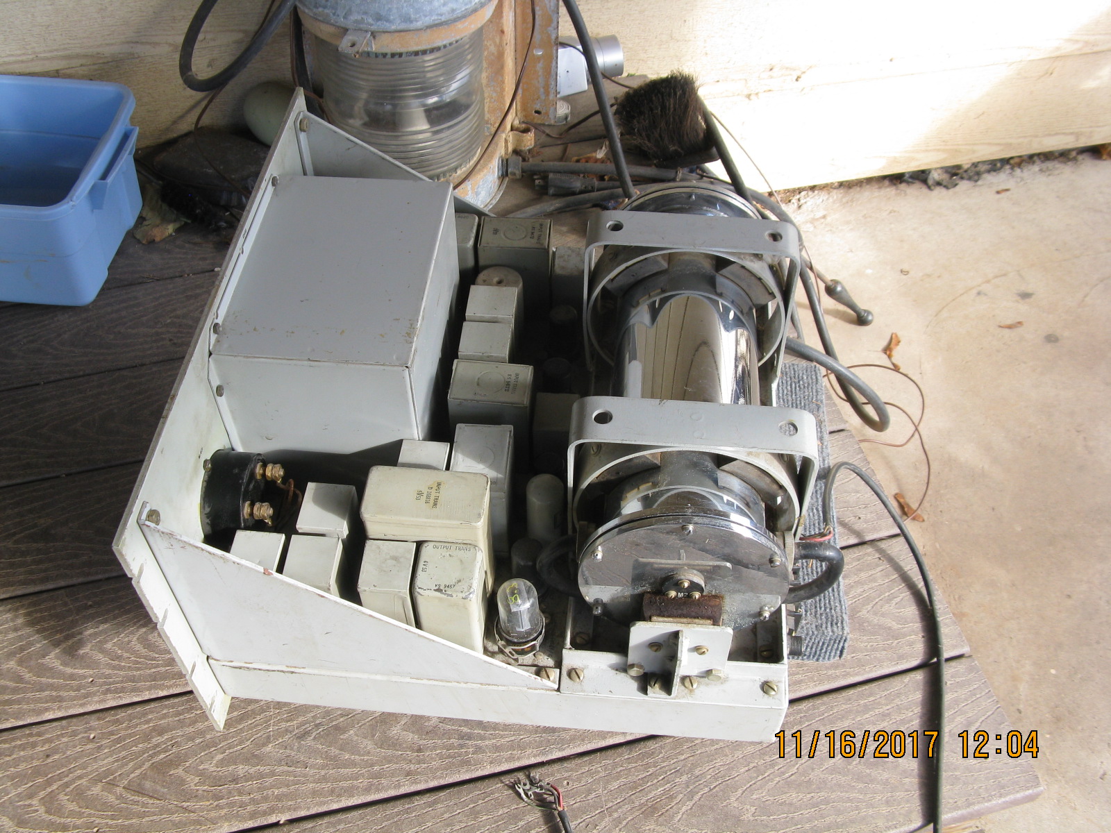
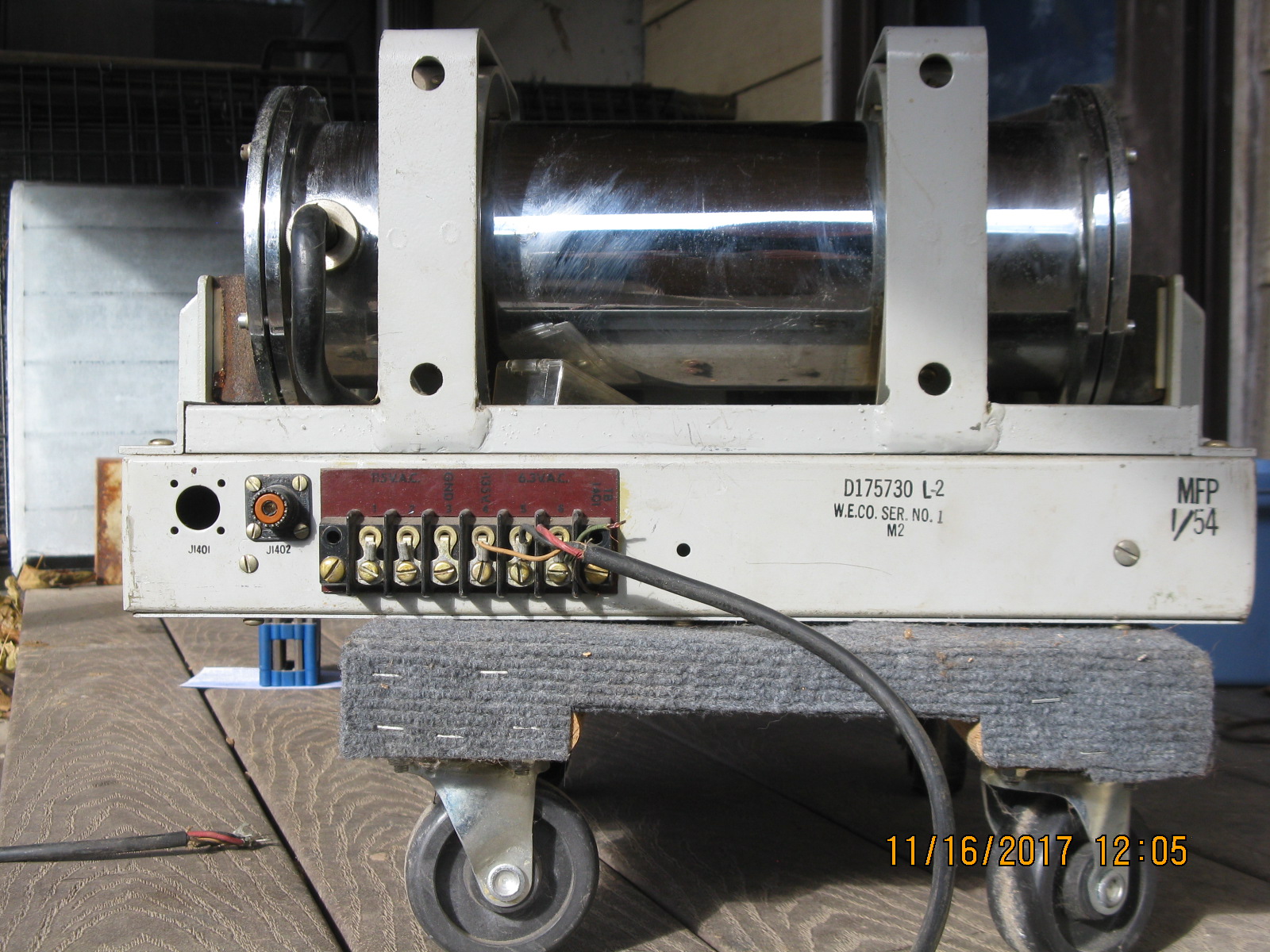
| O-76A/U Frequency Standard (part of AN/FSM-5A) Western Electric D-175730 |
 |
 |
 |
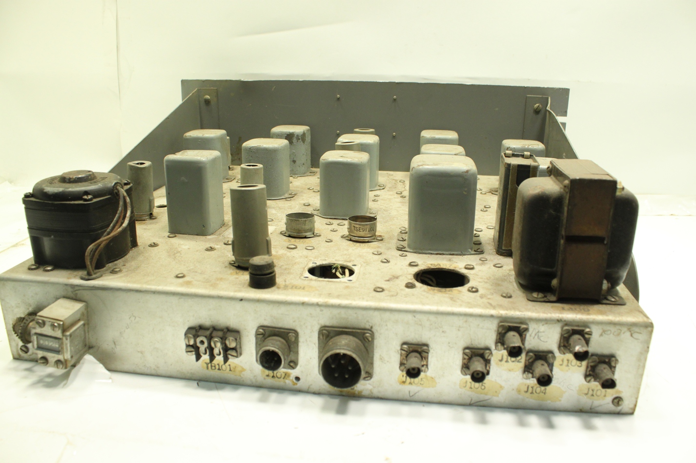
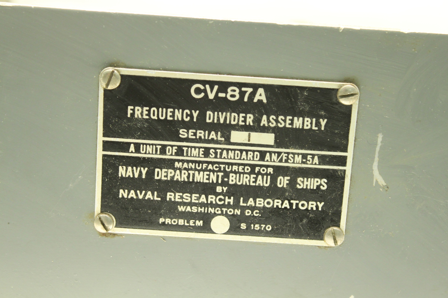
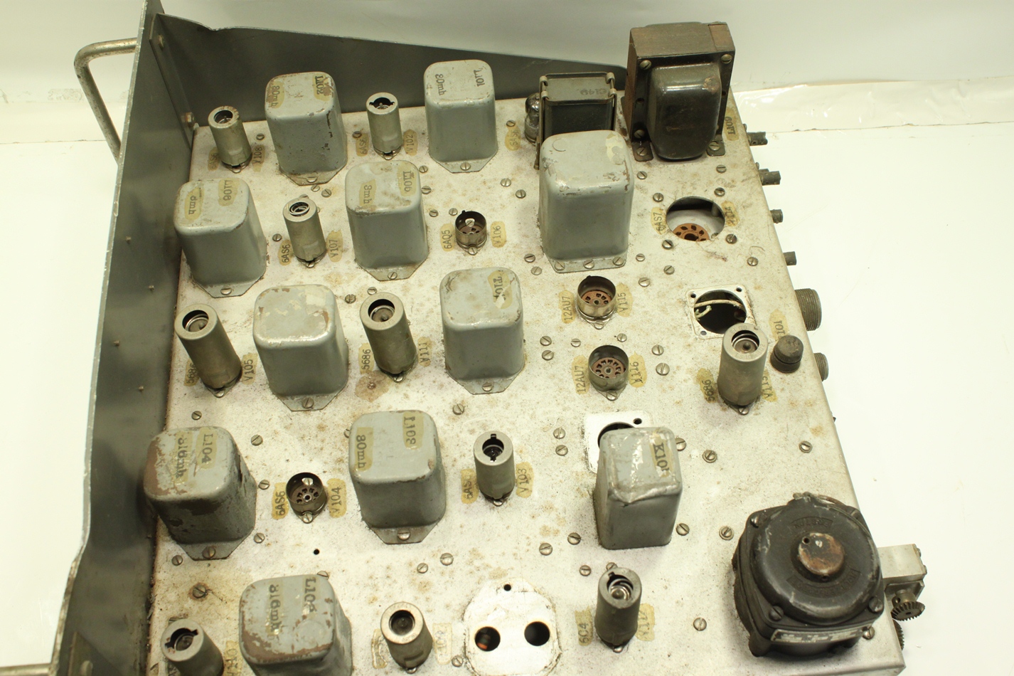
| CV-87A (AN/FSM-5A frequency divider) 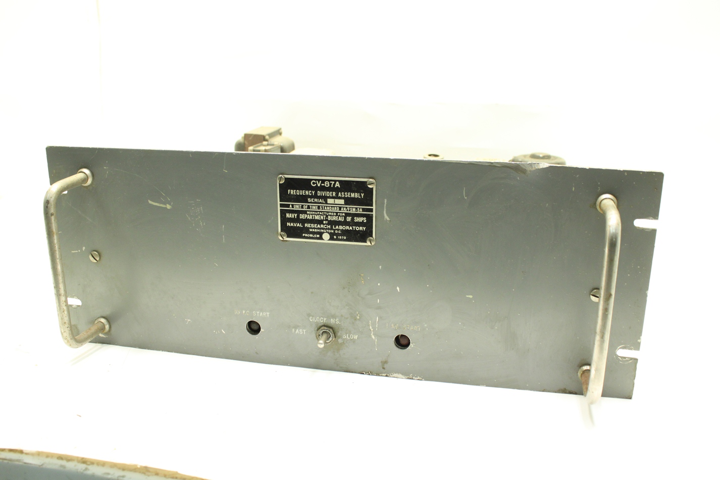 |
 |
 |
 |
TIME TRANSMISSION EQUIPMENT FOR REMOTE STATIONS
In 1951 the Navy required further increase in the accuracy and reliability in the transmission of its time signals. It had been transmitting time on high frequencies from its stations at Annapolis, San Francisco, Hawaii, and Balboa in the Panama Canal Zone, accomplished through the use of a telegraph line from the Naval Observatory to Annapolis and thence via radio relay to the remote stations. Variable errors had been experienced of up to 20 milliseconds in the Annapolis transmissions and over 100 milliseconds from the Hawaii and Balboa transmissions. After an unsatisfactory attempt to obtain improvements from commercial sources, NRL was requested to undertake the problem. NRL investigations revealed that the inaccuracies and unreliability were due to several factors, including variations in the wire line and in propagation, the reliance upon mechanical contactors to produce the time signals, and inadequacies in the time determination and transmission equipment at the Naval Observatory.
In dealing with this problem, NRL was first to develop a standard time-transmission system in which the several remote stations were provided with equipment to generate their own time-transmission signals with a high degree of accuracy, the errors of which could quickly be corrected by means of observations made at the Naval Observatory in Washington, D.C. (1953). The NRL-developed time-transmitting equipment (Model AN/FSM-5A) was first to utilize the leading edge of continuous-wave transmitted pulses generated by a quartz-crystal oscillator as a means of indicating a desired precise moment of time. This equipment was installed at all the Navy's time transmitting stations which provided coverage of the Atlantic and Pacific Ocean areas. The new system made possible for the first time transmissions from widely separated transmitting stations to a precision of one millisecond.
This Model AN/FSM-5A equipment utilized new pulse-delay and cathode-ray-display techniques for measurements to permit the precise control of the incidence of the timing pulses and to allow adjustment prior to the time transmissions. A novel regenerative type of frequency divider was devised which proved fully reliable in operation of the quartz-crystal clocks. The mechanical contactor, although retained to serve as a gate to pass the time pulses, no longer affected the accuracy of the leading edge of the time transmissions.
To improve substantially the Naval Observatory's time functions, NRL developed a quartz-crystal clock (Model AN/FSM-5B) which, for the first time, provided from a single crystal, power outputs simultaneously at both sidereal and mean solar frequencies to an accuracy of two parts in 10^10, equivalent to a possible error of one millisecond each century (1954). Power at the sidereal rate drove the star-image recording mechanism for the determination of time. The power at the mean solar rate was utilized in the observatory's surveillance and control of the time transmission of the Navy's several stations. This clock eliminated the long comparison process and errors involved in the two separate quartz-crystal clocks which previously had to be used by the Observatory in performing these functions. NRL's clock embodied a dual-frequency generator involving a special combination of electronic-algebraic operations to provide a sidereal to mean solar time ratio, as derived from Newcomb's right ascension of the mean sun. Power from the clock was also used to drive other astronomical devices at the Observatory, including its large telescope.
VLF WORLDWIDE PRECISION TIME AND FREQUENCY TRANSMISSION SYSTEM
The Navy has been transmitting precise time and frequency on the high-frequency band since 1927, when NRL first equipped the Navy's "Radio Central" station at Arlington, Virginia with high-power, high-frequency transmitting equipment, the Model XD, already described in Chapter 3, "Radio Communication." The capability of this station to transmit simultaneously on four selected frequencies assured broad coverage for the Navy's time service. Time transmission on high frequencies are still being continued from certain designated Navy radio stations.
Experience has revealed that the rapidity of the change in phase of the transmitted energy in this high-frequency band, due to movements of the ionospheric reflecting surfaces, limited the accuracy of time transfer over long distances to one millisecond and that of frequency and time interval to one part in 10'. Propagation observations in the VLF band established that transmissions in this band were much more stable and predictable both diurnally and seasonally. In 1959, NRL proposed that the Navy's high-power VLF communication stations be used for the simultaneous transmissions of precise frequency and time together with its communications. In accomplishing this dual time-communication transmission function, NRL devised phase tracking and other techniques and a time-signal format which provided the transfer of time on VLF over long distances to an accuracy nearly two orders higher than on high frequencies, or 50 microseconds, and the transfer of frequency and time interval to one part in 10^10, simultaneously with frequency-shift-teleprinter communications (1959-1973). NRL's developments were first applied to the Navy's VLF station at Summit, Panama Canal Zone (NBA) to meet an urgent operational requirement for more precise time rating for missile launchings at the Atlantic and Pacific Missile Ranges, now known as the National Missile Ranges (1959). The NRL developments as they became available have been applied to all of the Navy's high-power VLF radio stations, providing worldwide precise time and frequency service in addition to their communication function. This system currently serves other government organizations, commercial interests, and organizations of other countries such as England, France, Australia, New Zealand, and the South American countries.
Actually, the capability of the Navy's radio stations to operate at VLF in the frequency-shift-keying mode is a direct result of NRL's work on high-precision frequency stabilization, already reviewed. The necessary phase coherence and continuity were thus made available. For incorporation of time and time-interval transmission in the system, NRL developed the first radio receiver and auxiliary equipment which could automatically track and record the phase of the received VLF energy with high precision. Through observations with NRL's equipment and the correlation of the data obtained, prediction of the corrections necessary to compensate accurately for ionospheric variations could be determined. The observations also allowed the detection of sudden ionospheric disturbances and permitted taking the necessary action to deal with them.
Further NRL improvements have permitted time transfer between the VLF station at Summit, Panama Canal Zone (NBA) and Washington, D.C. to a precision of one microsecond and frequency and time interval to one part in 1013 (1972). These improvements resulted through NRL's application of electronic correlation techniques to the VLF communication system. These improvements were applied to all Navy VLF communication stations.


