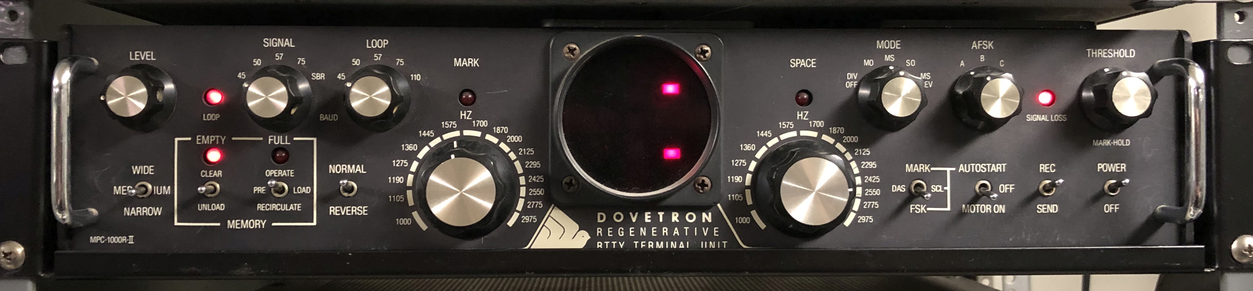
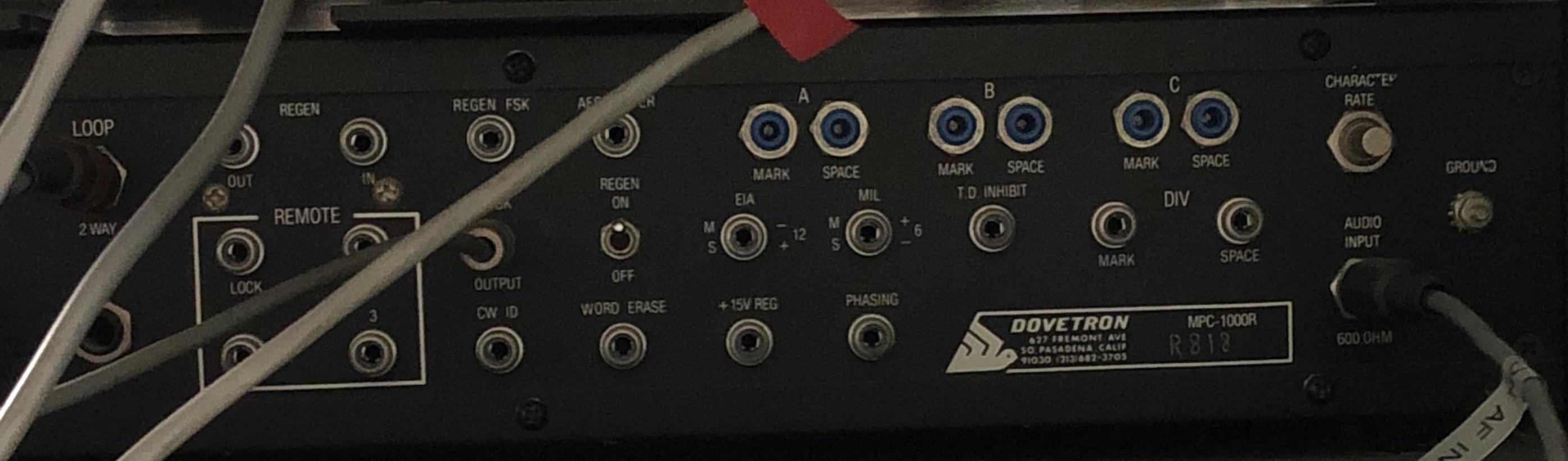
MPC-1000R-II Regenerative
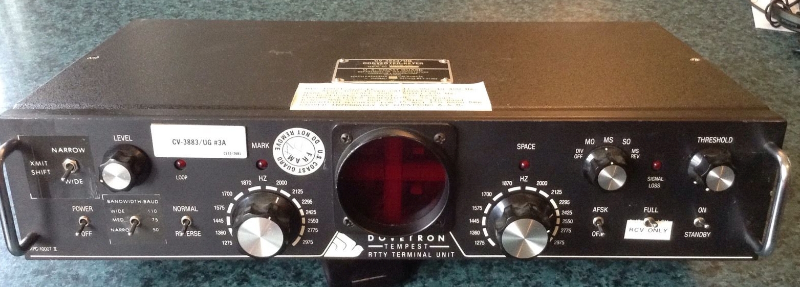
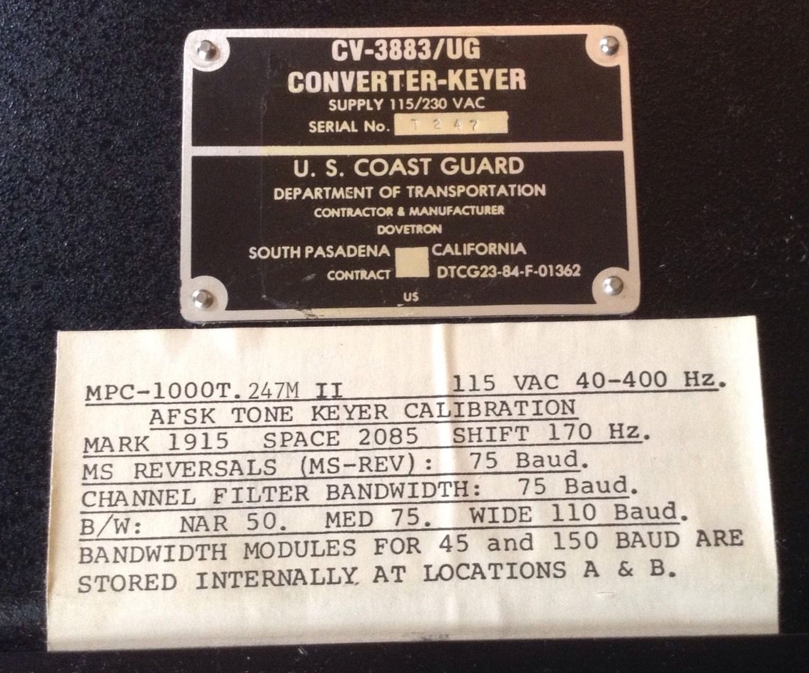
US Coast Guard CV-3883/UG - MPC-1000T.247M-II
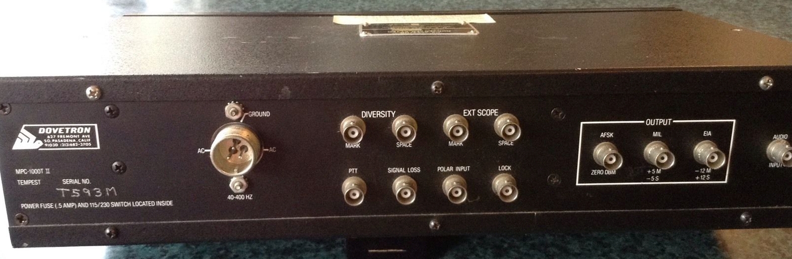
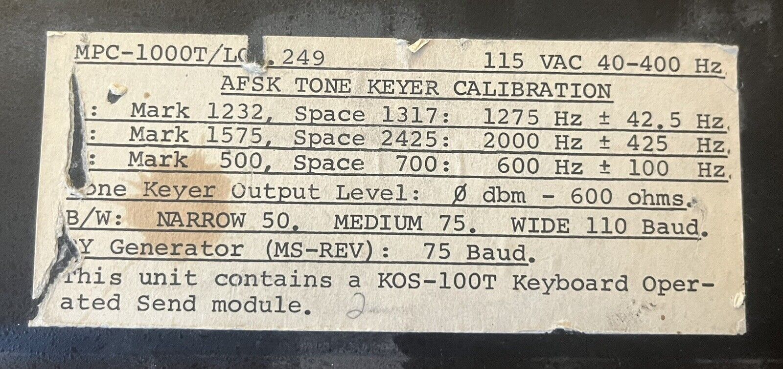
MPC-1000T/LCO-II Tempest
![]()
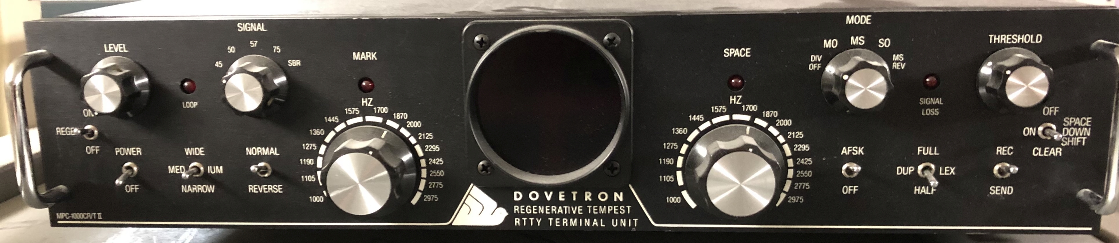
MPC-1000CR/T-II Regenerative Tempest
MPC-1000R-II Regenerative |
||
|
|
== | == |
US Coast Guard CV-3883/UG - MPC-1000T.247M-II |
||
|
|
|
== |
MPC-1000T/LCO-II Tempest |
||
|
|
|
MPC-1000CR/T-II Regenerative Tempest |
||
|
|
== |
== |
| MPC-1000CR/T Mark II Tempest Regenerative RTTY Terminal Unit manual (use with MPC-1000T manual below) Addendum to schematic |
| MPC-1000T Tempest Regenerative RTTY Terminal Unit manual |
| MPC-1000R Manual |
| Thanks to Michael VK2BEA for these scans MPC-1000 and MPC-1000C manual MPC-1000 and MPC-1000C control board schematic 75103 MPC-1000 and MPC-1000C control board layout 75100 |
| MPC-1000 and MPC-1000C control board schematic
and layout 75100 & 75103 Hi-resolution version - schematic and layout 75100 & 75103 |
| BPP-100 revision A schematic
75195 BPP-100 revision A layout 75192 BPP-100 revision B schematic and layout 75349 MPC-1000 board schematic marked with mods for BPP installation |
| SSD-100 LED Display schematic and layout 75307 |
|
Scanned by Don Robert House K9TTY TBA-1000 Code Translator Manual Serial No. 300 and Up 06 Jun 2010 Download 20 MB pdf |
| TSC-1000 Speed Controller Manual - 0.5MB pdf |
| TSR-200D Regenerator schematic - high res 75164 |
|
TSR-300D Regenerator/SELCAL board description WANTED -TSR-300D Regenerator/SELCAL board schematic - please send email if you can help |
| TSR-500 Regenerator 75139 schematic - temporary 75139 - better scans coming later |
|
Manuals compiled by Vernon G Schroeder K9POU (1929-2006) p. 01 - MPC-1000CR Regenerative RTTY Terminal Unit |
| Some more Dovetron info thanks to Harold W6IWI |
Another copy of these manuals is here
And also see here, here, and here
9/28/14 - Jim Haynes says -
If you have the Binary Bit Processor BBP-100 Mark II as shown on drawing 75349 then inspect the bottom side of the PC board to see if there is an extraneous trace connecting the top ends of R21 and R22. By top ends I mean the ends that are on top if you hold the drawing vertically so it reads right side up. The bottom ends are supposed to be connected together and to pin 6 of U11. The top ends are not supposed to be connected together. If they are the threshold voltage will stay at 0 volts so the threshold correction circuit is inoperative.
Then look at resistors R24 and R25. These are supposed to be 10K resistors. You may find they are 100K, because 1% resistors have an extra digit in the value. If the colors are brown-black-black-orange you have 100K resistors and the unit will hardly work at all after the extraneous PC trace is cut. So replace them with real 10K resistors.
9/29/14 - Jim Haynes says -
The design seems to have gone through many variations. The original design seems to be represented by U.S. Patent 4,013,965 and was all on the main board. The patent goes into great detail about how the anti-multipath circuit is supposed to work. Apparently that didn't work very well, so the parts were pulled off the main board and a new circuit called the Binary Bit Processor was built on a board that plugs into the main board and replaces the original design. This was supposed to be another anti-multipath feature. Mark I of the BBP is shown on drawings 75192A and 75195A. I don't understand that circuit, but then I didn't try very hard since I don't have one. Apparently that wasn't satisfactory either, because there is a Mark II BBP shown on drawing 75349B. There are at least two revisions of that board, having slightly different resistor values. The Mark II seems to have given up on anti-multipath and settled for a simple threshold corrector - or maybe I should say a complicated threshold corrector, but simple in principle.
You can get the patent from www.pat2pdf.org - Other patents issued to Hank Scharfe are 4,229,698 for the LED cross-pattern tuning indicator, 4,243,836 for a digital autostart circuit, and 4,415,964 for a power supply.