THE TT-63A REPEATER
IRVIN M. HOFF K8DKC - RTTY Bulletin April 1964
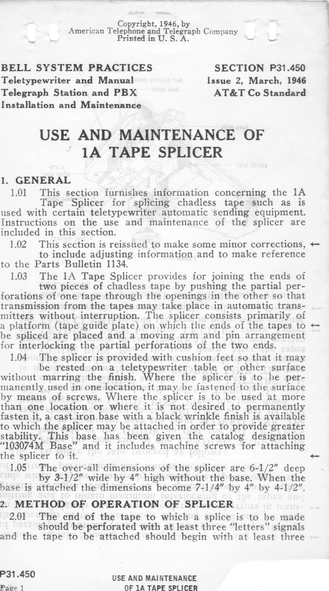
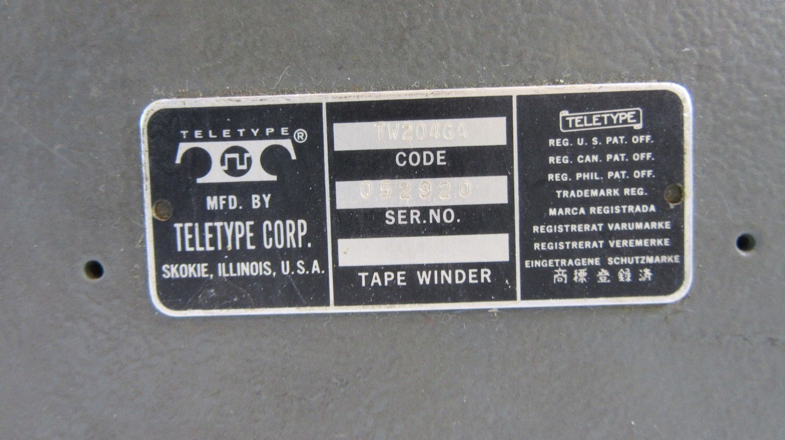
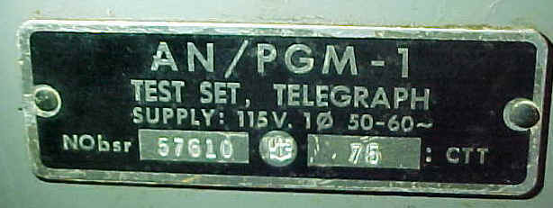
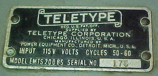
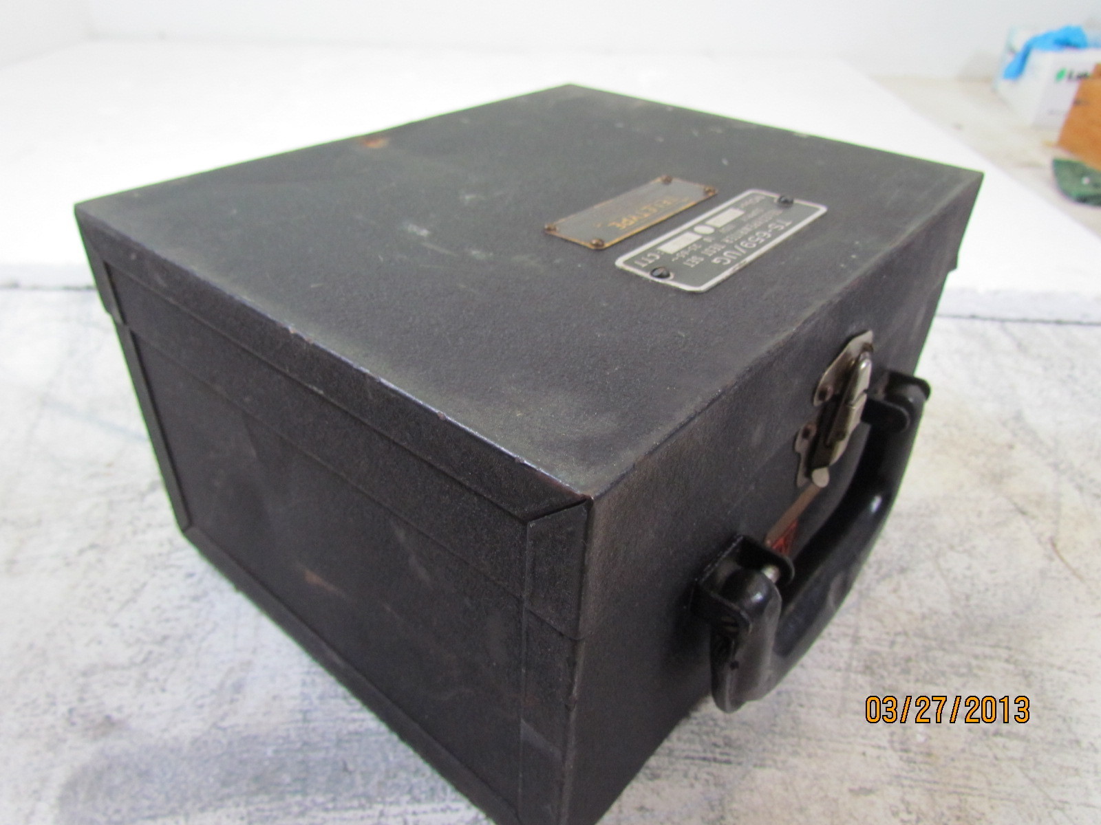
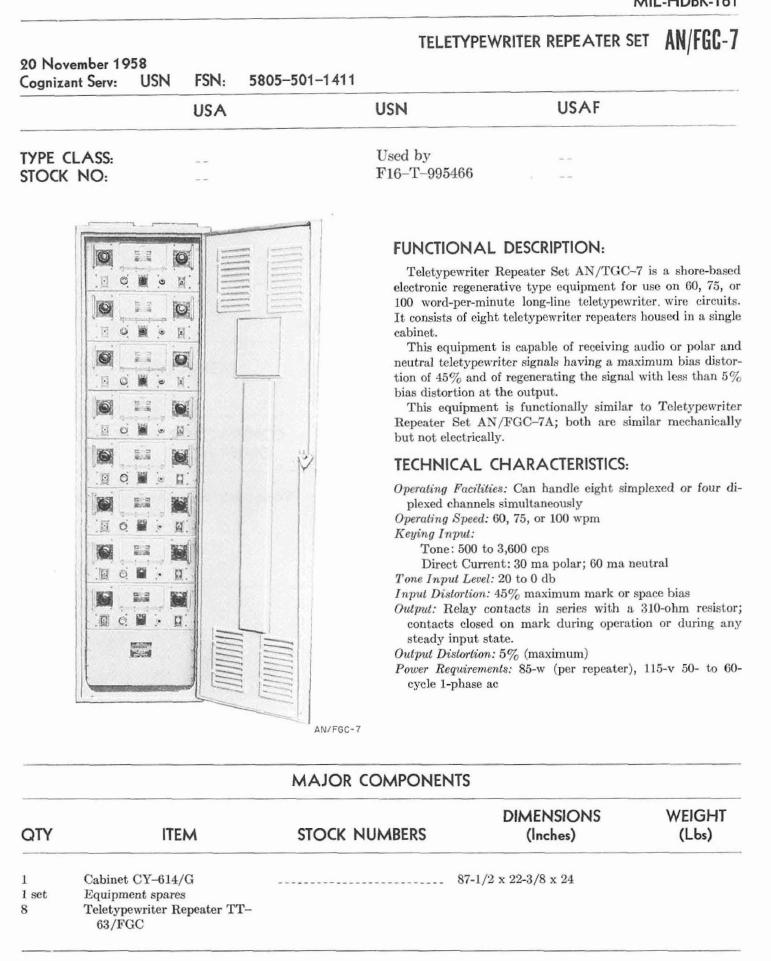
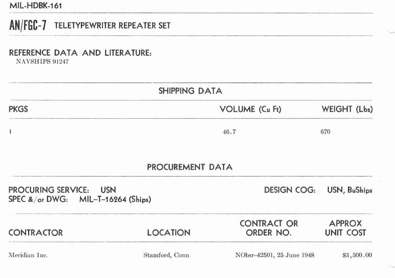
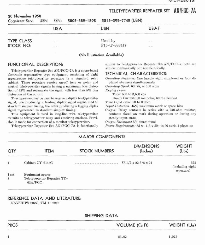
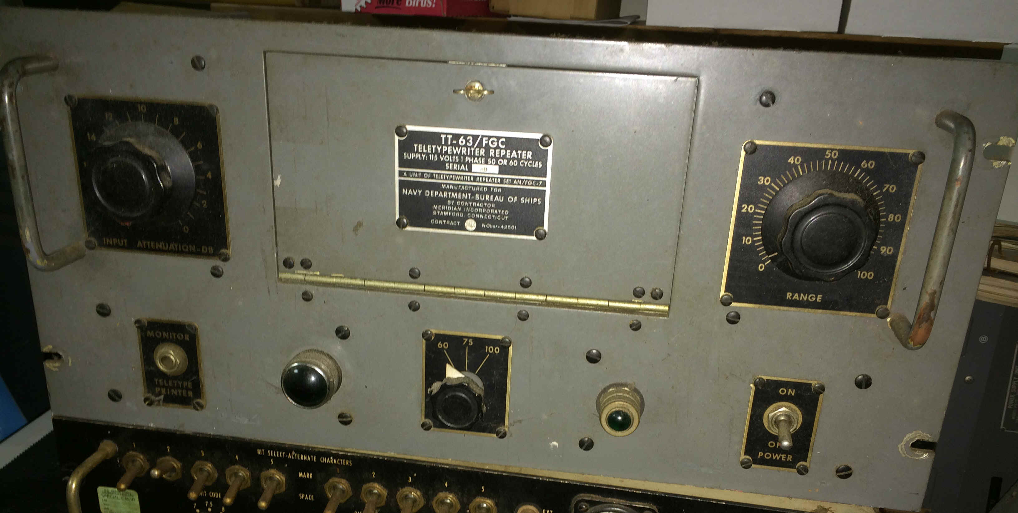
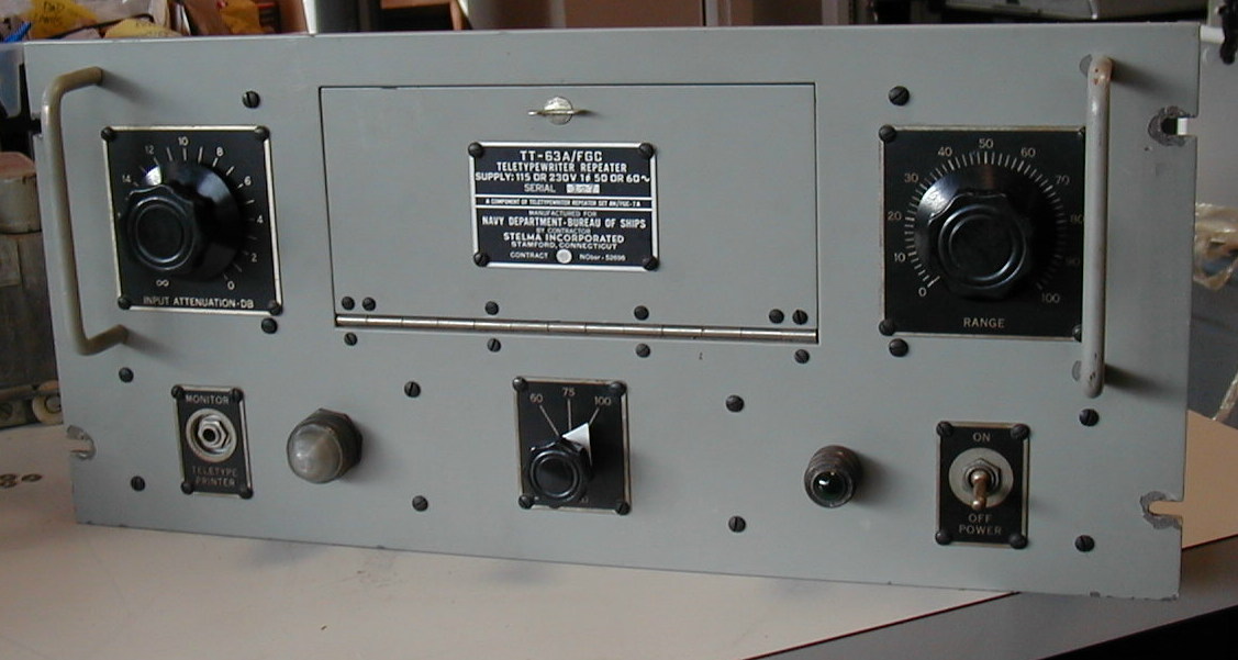
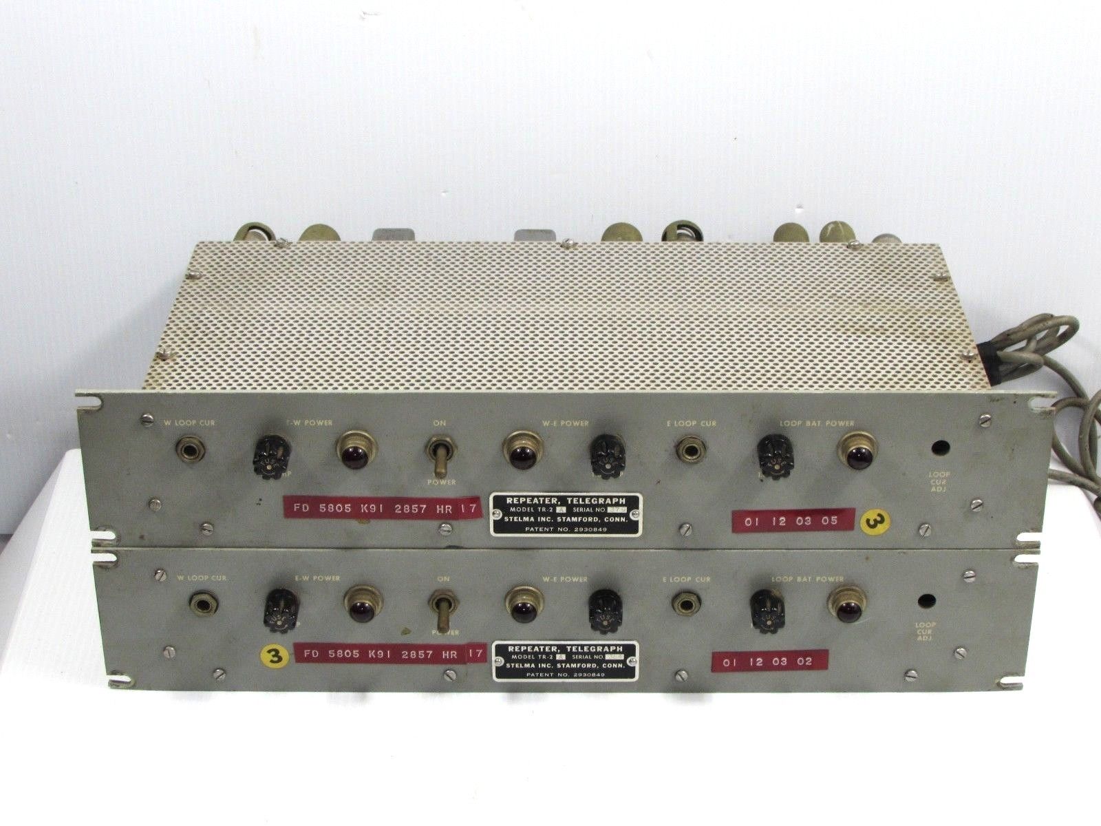
In recent months ads have appeared in various amateur magazines telling about a surplus government item called a regenerative repeater for teletypewriters. This unit was made for the Navy and is called the TT-63A/ FGC. They have been selling for slightly under $40, and a great number have been sold-unfortunately not very many manuals have been available (these items were part of a set called the AN/FGC-7A which used eight repeaters, and this would indicate some of the reason that manuals are scarce!).
What Is It?
A regenerative repeater can correct for extremely biased signals, and since it only samples a very small portion of the pulse (one millisecond versus about five milliseconds for the model 15 printer for example), this sample can be easily varied from the beginning of the pulse to the end of the pulse, by the operator. (Actually from 2-20 milliseconds.) This sample is then used internally by the repeater to trigger multivibrator circuits that "restore" the complete pulse once more as a perfect signal. Thus the repeater can be easily adjusted to counteract a biased signal without needing to correctly set the printer's range control- which is often difficult to get at. Another advantage of correcting the bias in the repeater circuit rather than at the printer is in the case you have several printers; or a printer and a reperforator in the same circuit. With the repeater, the output will be an excellent reconstructed perfect pulse; and all machines on the output of the repeater will print identically if they are adjusted to print well on a local loop.
WA9IBB (Jim Haynes) has pointed out that a "well-adjusted" printer in itself works as a regenerative repeater, and in this case a repeater has little to offer. This is correct, of course, but the repeater has several other functions available that add to its versatility. In the first place a "well-adjusted" printer is at times hard to come by. If your printer runs from maybe 15 to 100 points or so on a local loop and prints well between those extremes, it could be considered "well-adjusted." It should print well on nearly any RTTY signal that is not horribly biased, with no further adjustment. By varying the range setting intentionally, you can move the five millisecond sampling area from the middle of the 22millisecond pulse toward the beginning or the
end to help counteract marking or spacing bias on the incoming signal. However, the chances that you will do this are remote. Instead you will probably just tell the fellow that you cannot copy him. On the other hand, the repeater has a range adjusting knob right on the front in a prominent position and can be quickly used not only to counteract for bias, but also to FIND AND DETERMINE BIAS.
So among other things, the repeater works as a form of bias meter; if the range knob is to the left (around zero) and the printer stops accurately printing, the bias is spacing, which is most usually the case.
If the knob is toward the right (100 ), the bias is marking. An excellent signal will print correctly from 0-100, representing 2-20milliseconds. As you can imagine, not many signals will print the entire range perfectly. One need not send any special characters or at any special speed to determine the type or presence of bias. This unit will not measure HOW MUCH bias directly, but you can get an idea if it is a small amount, medium amount or lots of bias by how nearly you approach 0 or 100, etc.
Another feature that will appeal to some is the false start gate. It is difficult to explain how this works, so we will tackle that later, but for now it is enough to say that it will take at least a 10 millisecond start pulse to trigger the unit. So on short bursts of impulse noise or static, this unit will not respond. The printer probably would if not used in conjunction with a repeater.
Another feature of interest is the mark-hold circuit. In the event you walk away and turn the receiver down, the mark-hold takes over and the printer remains idle. In conjunction with VHF, etc., (where the squelch blocks off the receiver output in the absence of any signal) this makes a rather effective autostart system.
Another feature is the unique manner by which the sampling is taken. Since this triggers a multi-vibrator circuit, if the signal happens to be a continuous space signal, then after printing one blank key, the printer again locks up until a transition occurs to again trigger the multi-vibrator. Essentially, this gives you "mark-lock" even on a constant space signal, after the first blank letter was printed. Thus if a station sends its CW ID on NFSK on mark or space either one, the
printer will tend to stay in idle. (This assumes the NFSK was narrow enough to stay in the mark or space filter during the ID.)
There are many other features which enable this unit to be used in other manners. Since it has character-recognition circuits in it already, it could probably be used in connection with a series of binary counters for autostart on lower frequencies such as 80m. It can be used to key transmitters directly; one fellow is using it to trip a "sounder" for CW as he copies that better than MAB CW; and last but not least it can be used as a converter, directly. For this purpose, it would take a very narrow IF position on the receiver for copying only the mark signal or space signal alone, plus a loop circuit in the output to drive the printer. Fairly narrow audio filters such as the FL-8 tone filter have been used with this unit as a converter. However, it should be pointed out that this gives only moderately good copy unless the signal is quite strong. This would work in a similar manner to other normal converters being used on Mark only or Space only copy-sort of marginal on MAB-it was for this reason, mostly, that the two-tone converters are being developed.
All in all, this unit enhances the station of the serious amateur, particularly the traffic man who likes to reperf incoming material. With this unit, the reperf and the printer will both print the same.
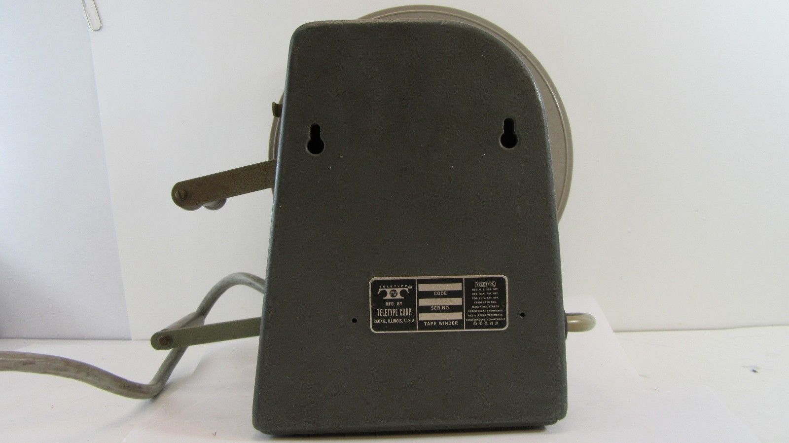
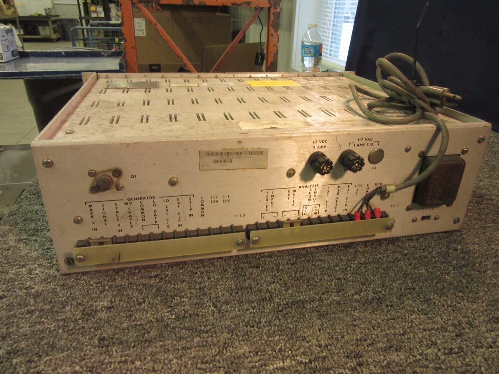
 Hooking the Unit Up Hooking the Unit Up
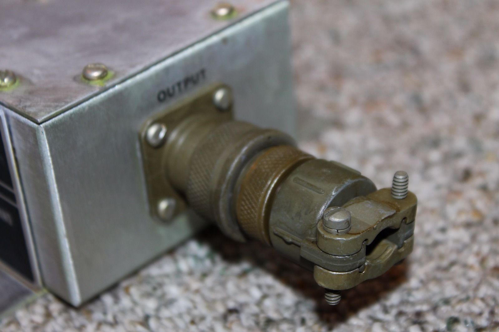
There are 3 inputs on the rear of the TT63/A. One for direct audio (AC); one for low-impedance DC neutral keyed (on and off) and one for DC polar keyed (plus and minus). For the most convenient use, none of these are best to the average amateur. If you already have a converter with a keyer tube circuit, this unit can be readily adapted so that you can use either the repeater or the keyer tube.
The first three stages are only concerned with the audio input, which in all likelihood you will never use.
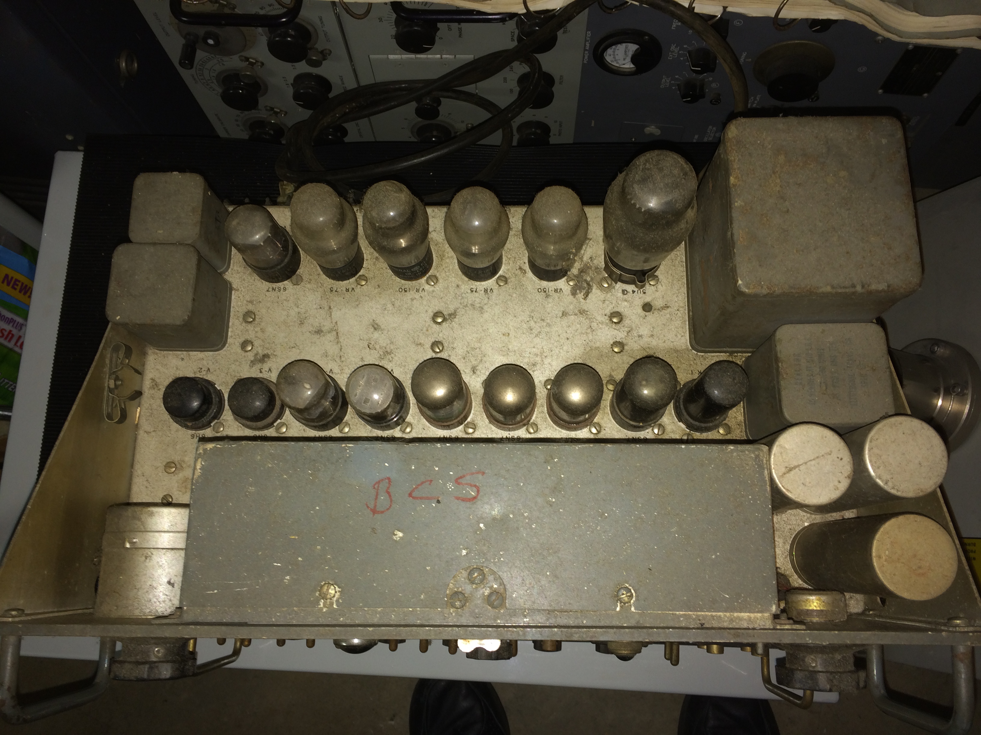
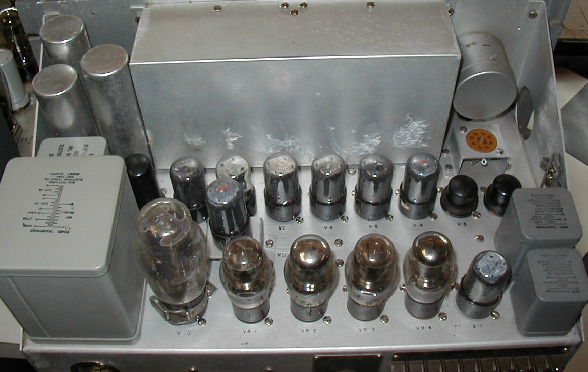
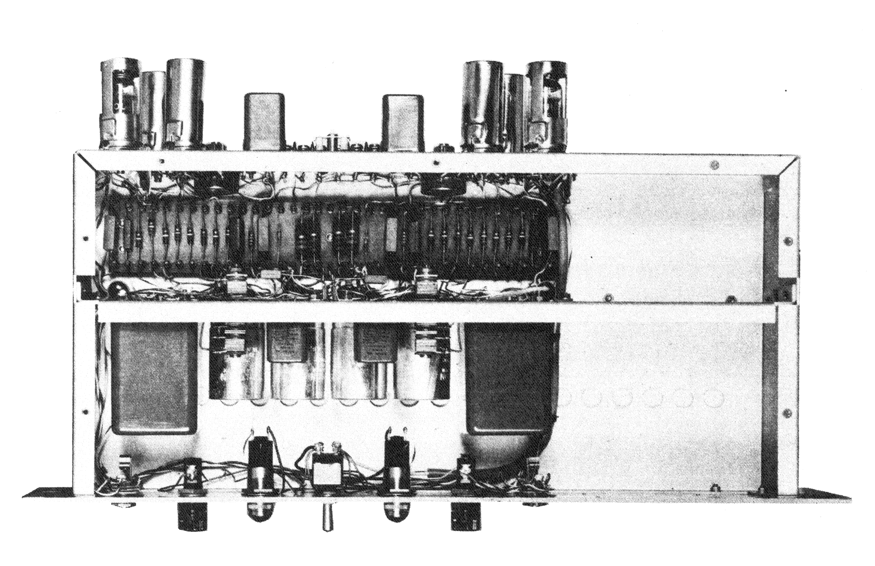
What we really need is a high-impedance polar-keyed input. This can be quickly and easily obtained with a simple modification. First find tube V-4-they are clearly marked on the top of the chassis. Then turn the unit over and remove the bottom plate.
Again find V-4 inside the unit. Remove the two green wires from pin 4 and tape them (separately is ok) for possible future use. Now run a wire from pin 4 to the terminal strip on the rear-to one of the "spare" contacts.
You now have modified the unit to high impedance, and a normal polar-keyed signal such as is normally gotten from the output of a flip-flop stage or a Schmitt trigger (or a DC amplifier stage giving a large plus and minus swing from mark to space), will work ok.
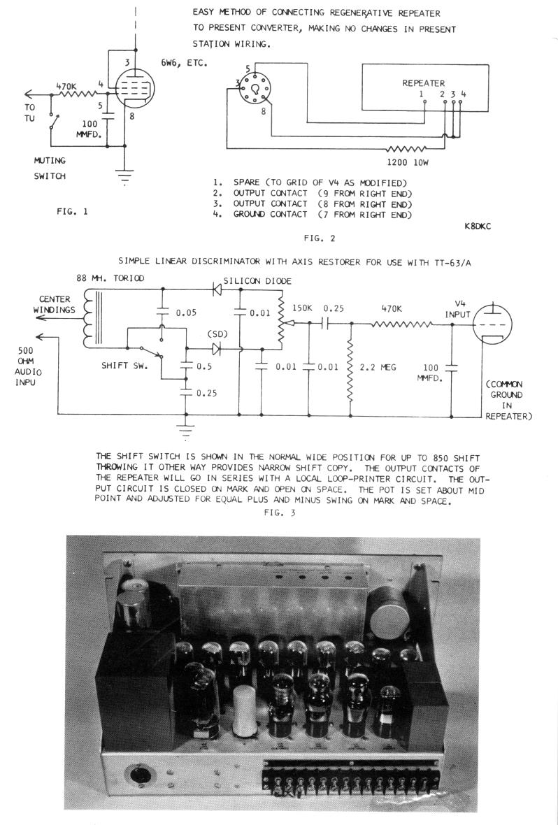
Figure One shows a typical 6W6 output stage in a converter.
We have all the ingredients right here to now use the converter with no other part needed except one more resistor which will drop the same voltage as the keyer tube, which we can replace readily.
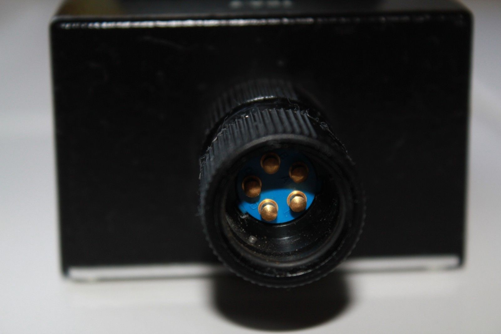
Get an octal male plug with cover-wire it as shown in Figure 2. You are then finished when you connect those wires to the terminals of the repeater. In some converters such as the Electrocom, the keyer tube is located inside the converter and not easy to remove. We have a circuit worked out for that purpose if anyone is interested, but please send a large-sized self-addressed, stamped envelope in that event. With this method, you can use the repeater on various converters easily and quickly; or change back-and-forth on any regular converter to note the effect. We can't include circuits for every configuration in a simple article, but probably you can integrate one into your present station easily enough.
Just remember that the output on the repeater is merely a mercury-wetted relay that opens and closes. It will be closed for mark and open for space. There are many ways it can be used, and only one has been presented here to accommodate the majority of converters.
It should be clear from Figure 2 that the 6W6 is removed from the tube socket and the repeater plugged in. No other adjustments should be necessary and the loop current should remain the same. The 1200 resistor was computed for a 30 ma. loop, and if you do not have the same current with the repeater you had with the tube, try a different sized resistor.
The Repeater as a Converter
With a simple input filter, the repeater CAN BE used as a simple MAB (Make-And-Break) converter. However this is far from satisfactory and W8SDZ has worked out a simple linear discriminator with axis restorer for use in front of these converters. See Fig. 3. This circuit was adapted from the balanced bridge linear discriminator used in the DynaKit FM tuner, and requires no limiting for
satisfactory performance. It takes only one toroid, and has been modified to allow narrow-shift reception as well as wide shift. A band-pass input filter ahead of this unit would have some merit; otherwise use the sharpest IF selectivity in the receiver that allows both mark and space to pass. This combination is not intended to be the "ultimate" in RTTY reception, but the axis
restorer does allow good copy automatically on mark only or space only, and thus a considerable latitude in mis-tuning can be tolerated. As a result no tuning indicator is included in this simple presentation. This circuit includes a low-pass filter, of a simple type which is quite effective in helping to achieve a more narrow bandwidth. This circuit gives surprisingly good copy, and in fact does better than many expensive circuits under many conditions of selective fade, etc.
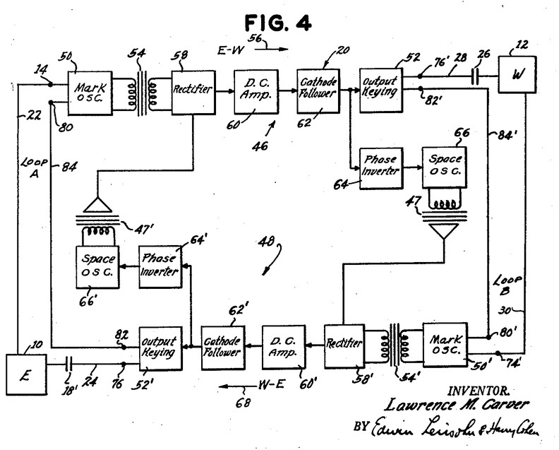
Theory of Operation
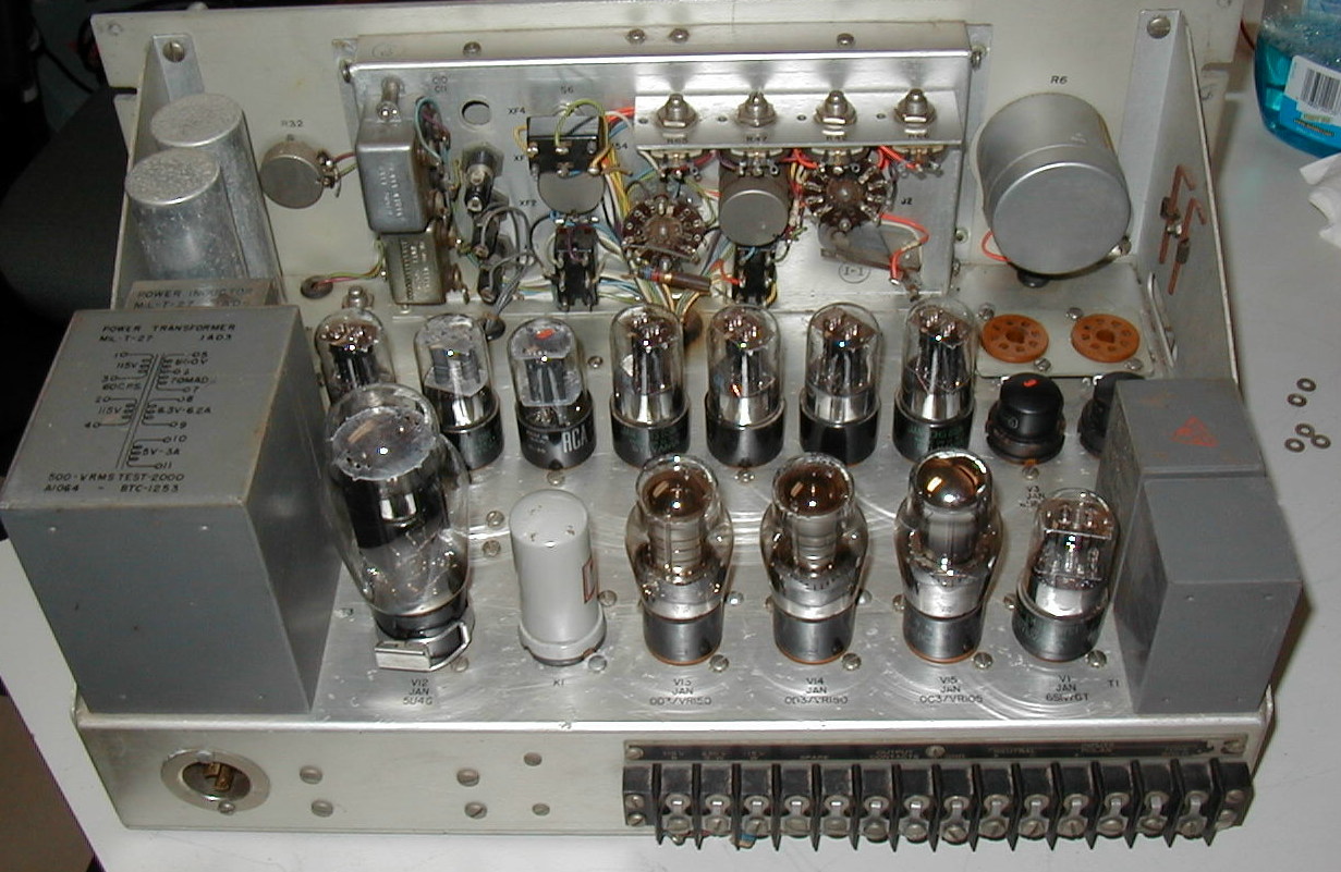
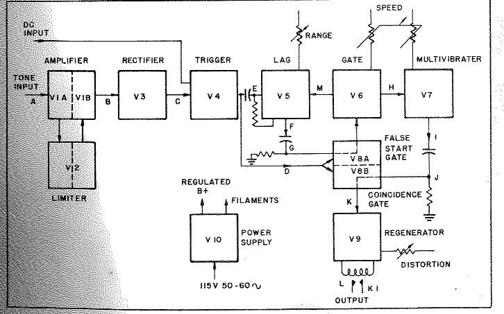
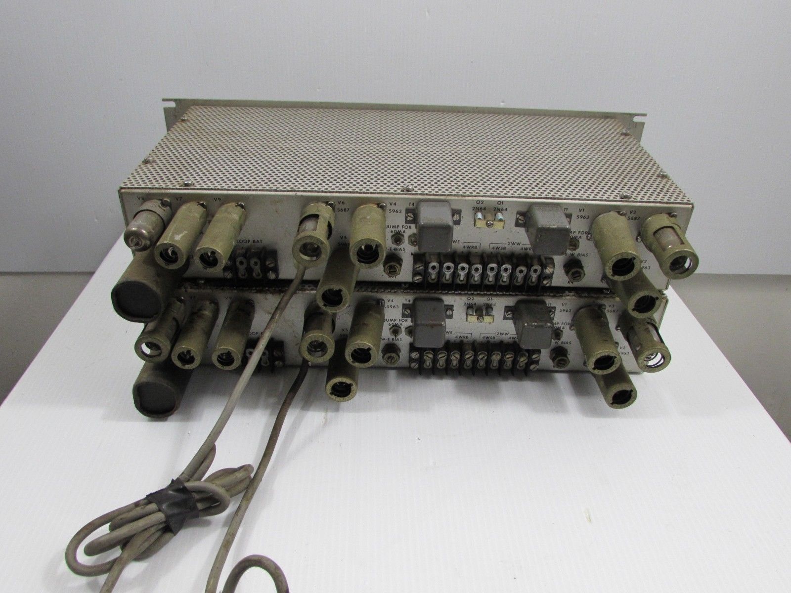
To really understand the action of the various stages (there are 14 tubes; a rectifier and a mercury-wetted relay!) one should really study the manual which has an excellent discussion. However, a quick run-down can be made at this time. The first three tubes are used only if one is using low-impedance audio single-tone input. In this case, the tone signal is amplified by the first section; limited by the second section; and again amplified by the first section of the second tube. This is rectified in V3 and fed to the trigger tube, V4.
Normal DC input is fed into V4 which is a direct-coupled flip-flop stage. This flip-flop generates a uniform square wave voltage which is essential for best operation of the following sampling pulse generating circuits and gating circuits.
Output from this tube is used to trigger a one-shot multi-vibrator lag tube V5. This output is "differentiated" and applied to a false start gate. This sample may be varied by the range control on the front from 2-20 milliseconds from the beginning of the start pulse. Normally it would be in the middle of this range.
There is a switch for 60, 75 and 100 wpm so that operation of this RANGE CONTROL is about the same for any standard speed.
Output from V4 also operates V8 which is the false start gate. This tube is biased off so that an output from V4 causes it to conduct, and depending on the position of the RANGE CONTROL, a noise burst of less than 11 milliseconds will allow this tube to again be cut-off, and it will not trigger V6. In this case no output can result.
This is one of the more important features of the repeater. Perhaps we could state this another way. If the. RANGE CONTROL is set at normal mid-range, then it would take a start signal of at least 11 milliseconds to keep V8 conducting so that the sampling pip through V5 would trigger V6. This of course can be varied with the RANGE CONTROL so that start pulses from 2-20 milliseconds would be required for the repeater to operate on that particular start pulse. However, if one delays the RANGE CONTROL too far to guard against noise bursts, then you stand the chance of missing the start pulse entirely if it might be distorted, and it is possible that you could trip off on the first mark-to-space transition instead; which would disrupt synchronization for several characters.
If the start pulse was a good TTY signal then the output of V5 is applied to V8, which in turn triggers V6, which is another one-shot multi-vibrator and runs for 143
milliseconds. Since a character is 163 milliseconds in duration, then you see this "timing" runs out in
the middle of the stop pulse. Depending on the setting of the RANGE CONTROL, this will be either toward the beginning of the stop pulse, or toward the end.
Once V6 is "fired" then it in turn turns on a third multi-vibrator tube, V7. This output fires every 22 milliseconds and the output differentiated into 1 millisecond samples; one for each of the six 22 milliseconds pulses and for the stop mark.
These sampling pulses are applied to both sections of coincidence gate tube V9, which operates in a similar manner to false start gate V8.
From here on, the action goes through phase reversal sections in order to operate the bistable trigger tube V10, which in turn drives the cathode follower tube V11 which drives the output mercury-wetted relay.
A feature of this converter which is very nice on autostart, etc., is that by use of the MARK-HOLD switch, a pulse from the V6 gate tube triggers the bistable trigger tube V10 to mark at the end of each gate cycle. Thus the output will return to mark EVEN IF THE INPUT GOES TO STEADY SPACE. For instance, if a CW station got on your space frequency, it could trigger the printer for one cycle-(which would print a "blank" key in all probability) and then the printer would lock up. The printer would also have a tendency to remain locked up if the CW station were on MARK frequency, depending on the position of the RANGE CONTROL, and the speed of the CW station, etc. Summary
If your printer is in top-notch condition, then you will notice little if any improvement in the copy during periods of normal conditions. However, the repeater will "cover up" very nicely for a machine which is in other than good adjustment. It will easily allow one to copy signals that are badly distorted either mark (up to 45%) or space (up to 45% also).
It acts as a rather nice indication of what type of bias a transmitting station has, and approximately the amount, with no special letters being needed.
It offers some protection against noise accidentally tripping the printer; and offers some protection against CW stations with the mark-hold, etc. If a station identifies on CW with a space frequency, it will lock up the printer and remain locked up.
Probably the best reason one would have for using such a device is in copying other signals onto tape equipment, as all machines in the station will then print the same, since this machine puts out a perfect "regenerated" 22 ms. square wave pulse. All machines will print the same errors, so tape copy and printer copy will coincide.
A few fellows "retransmit" onto other circuits and other transmitters, etc., and this system will offer optimum range to those other circuits.
All in all, to the serious enthusiast, the $40 price for this item seems to be well worth investigating, and for the station just starting, with the circuits included, one can make a decent converter for around $50 or less which can then be used later in conjunction with other equipment constructed, since the repeater is normally used behind a regular converter.
|


