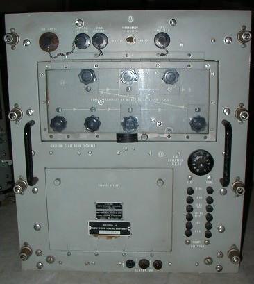
RFO front panel
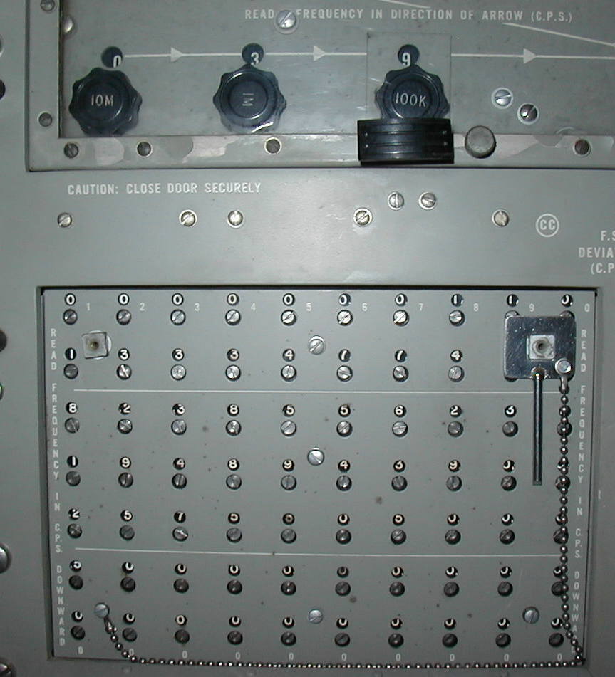
manual freq. switches above
10 channel freq. switches below
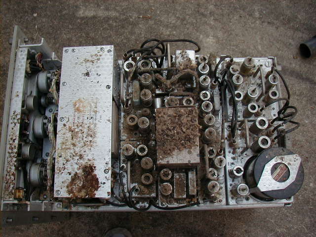
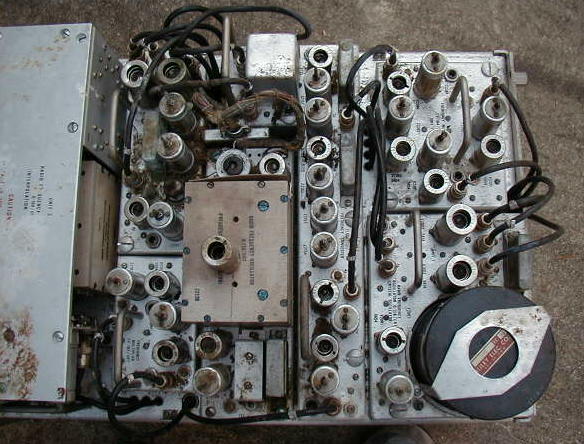
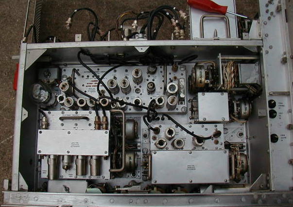
after removing top cover - it ain't pretty! - located directly below nest in LLRM
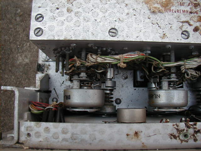
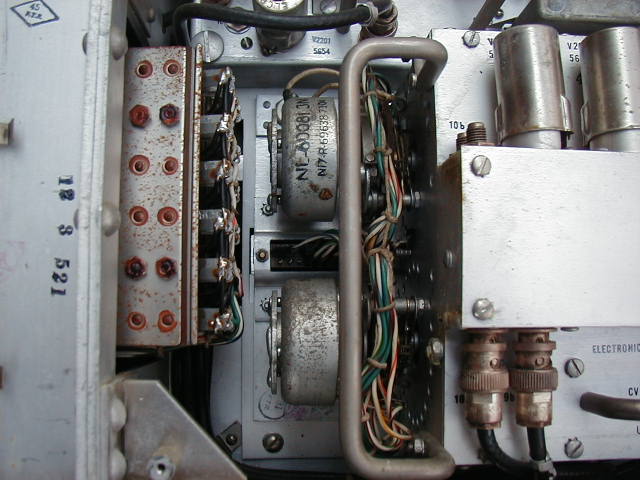
frequency selector steppers
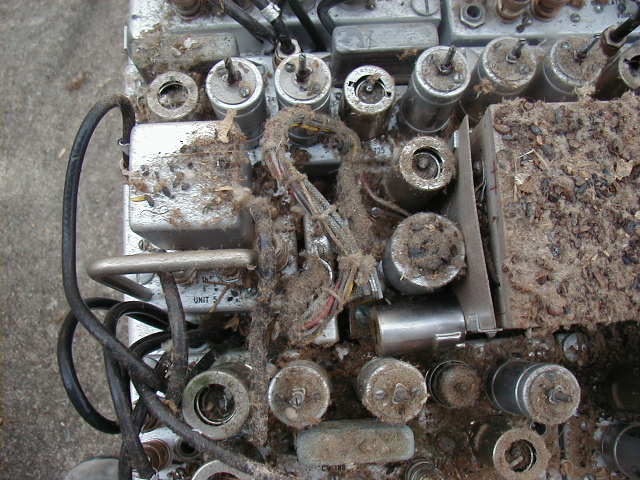
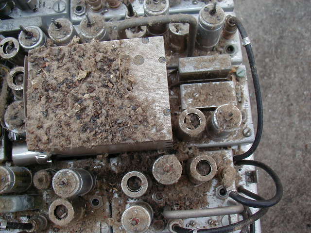
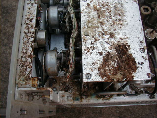
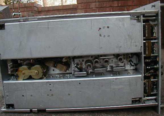
after initial vacuuming - I then removed each module and cleaned it

right side - a little staining but basically looks OK

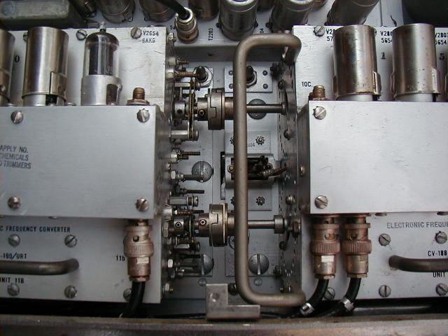
right side Oldham couplers
left side - a little staining but basically looks OK
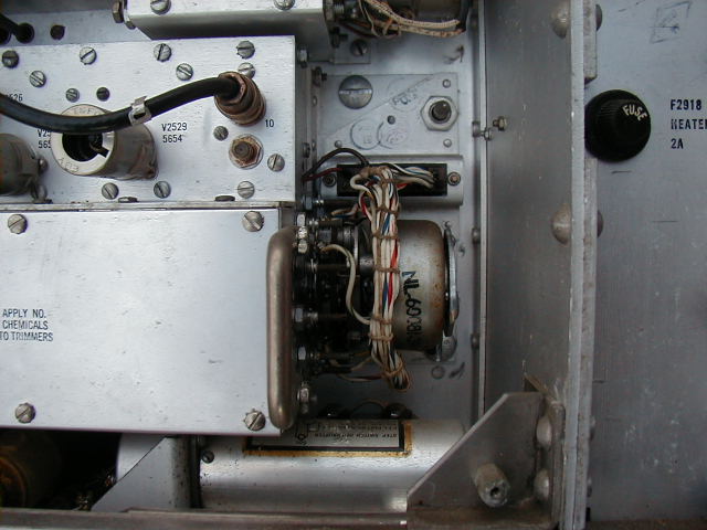


remote selector stepper switch

bottom - rectifiers
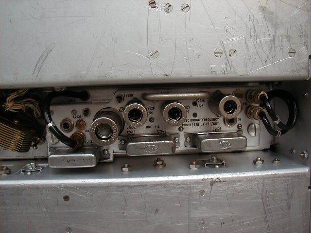
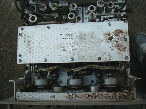
bottom - module
bottom