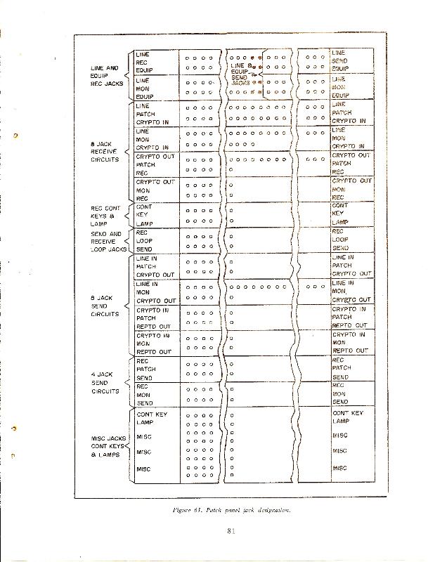
RED teletype signal patch panels are used on the plain text side of
encryption equipment and BLACK/GRAY patch panels on the encrypted side. If a piece of
teletype equipment can switched between the two, a locking switch and indicator
lamp are used to avoid mistakes.
|
|
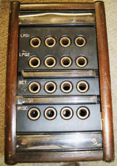
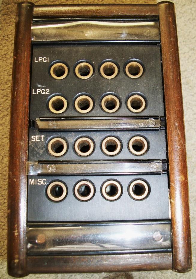
TT-23()/SG
includes a switch for
each channel to select external or internal loop supply
Schematic
Description and connections
TT-23/UG - NAVSHIPS 91103
TT-23B/UG - NAVSHIPS 91480
|
6 channels
2 LPG, 1 SET, 1 MISC
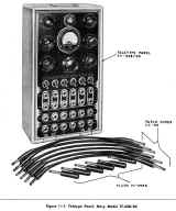
photo thanks to WA5CAB
|
|
|
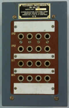
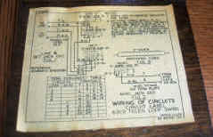
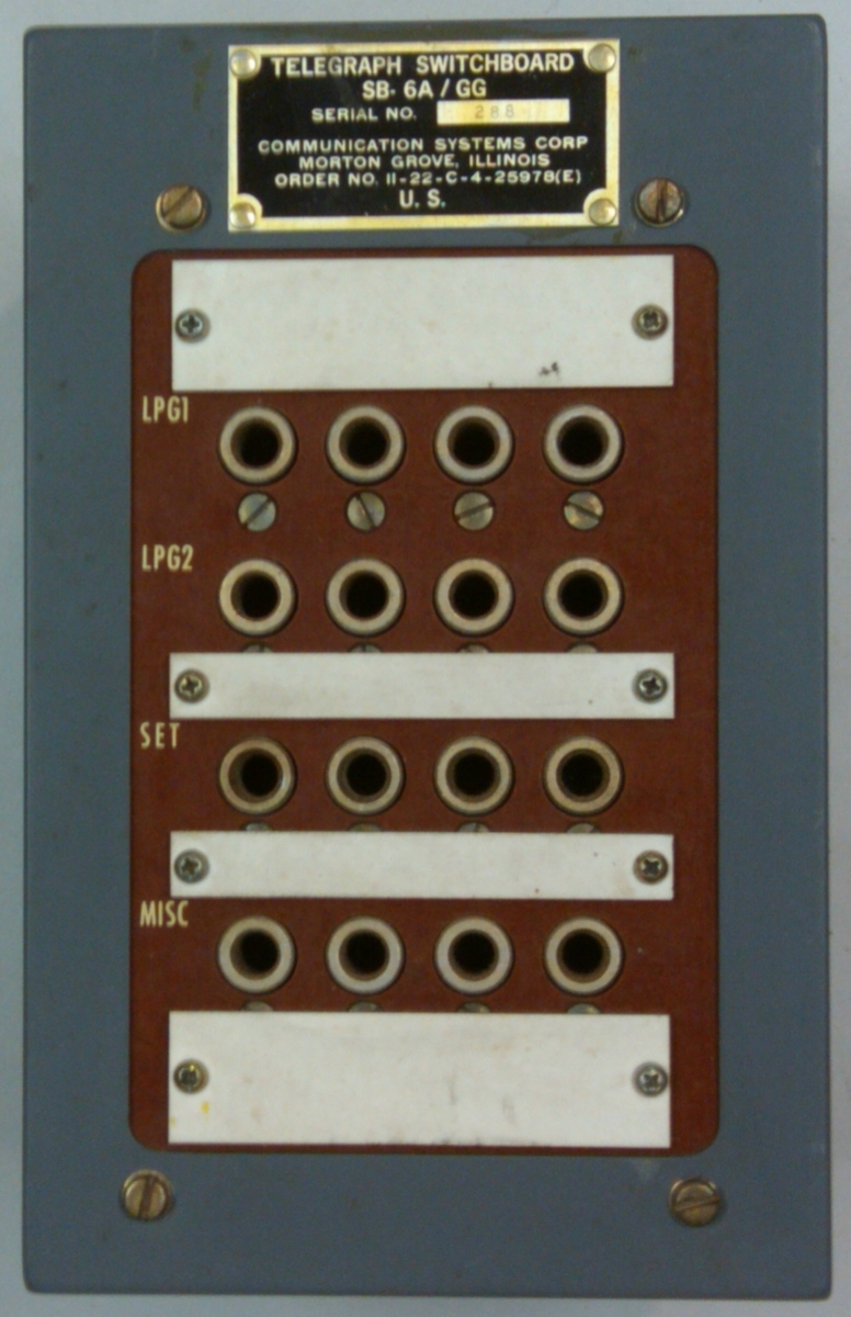
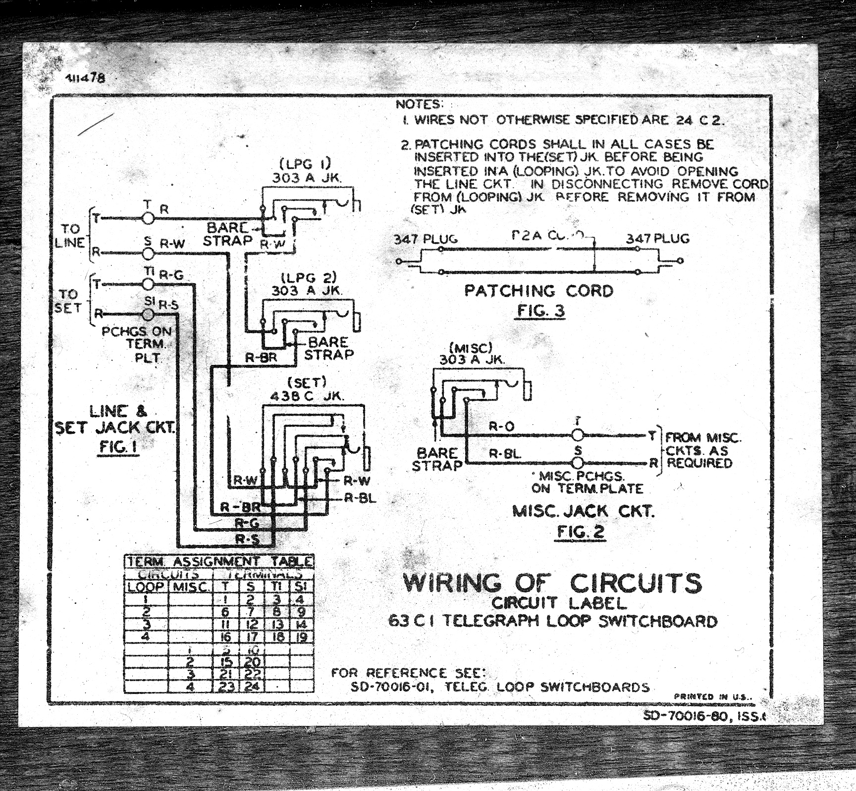
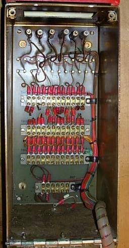
SB-6/GG
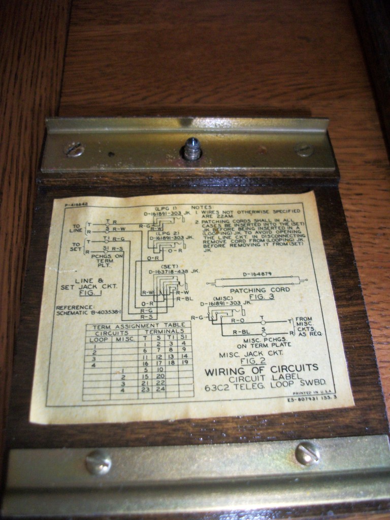
(Western Electric 63C2)
SB-6A/GG
|
SB-6A/GG (Signal Corps)
thanks to Kevin
|
Download SB-6/GG manual
4 Channels
2 LPG, 1 SET, 1 MISC
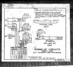
63C1 wiring diagram
thanks to Roy
 |
|
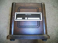
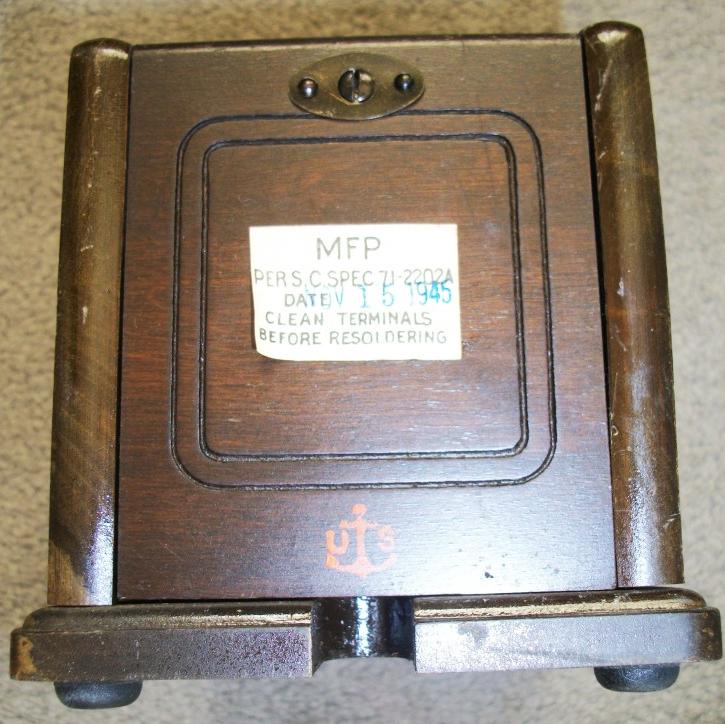
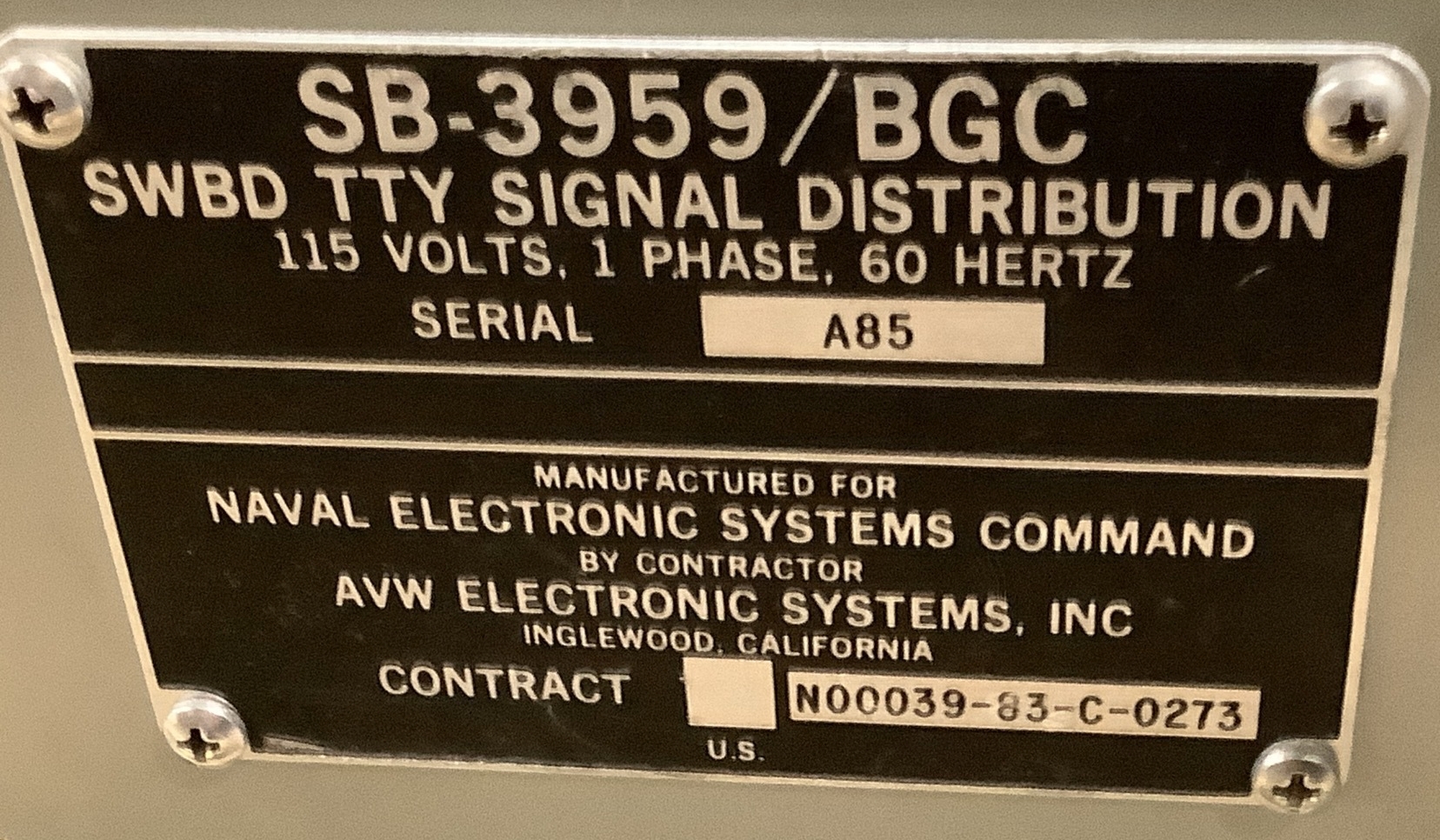
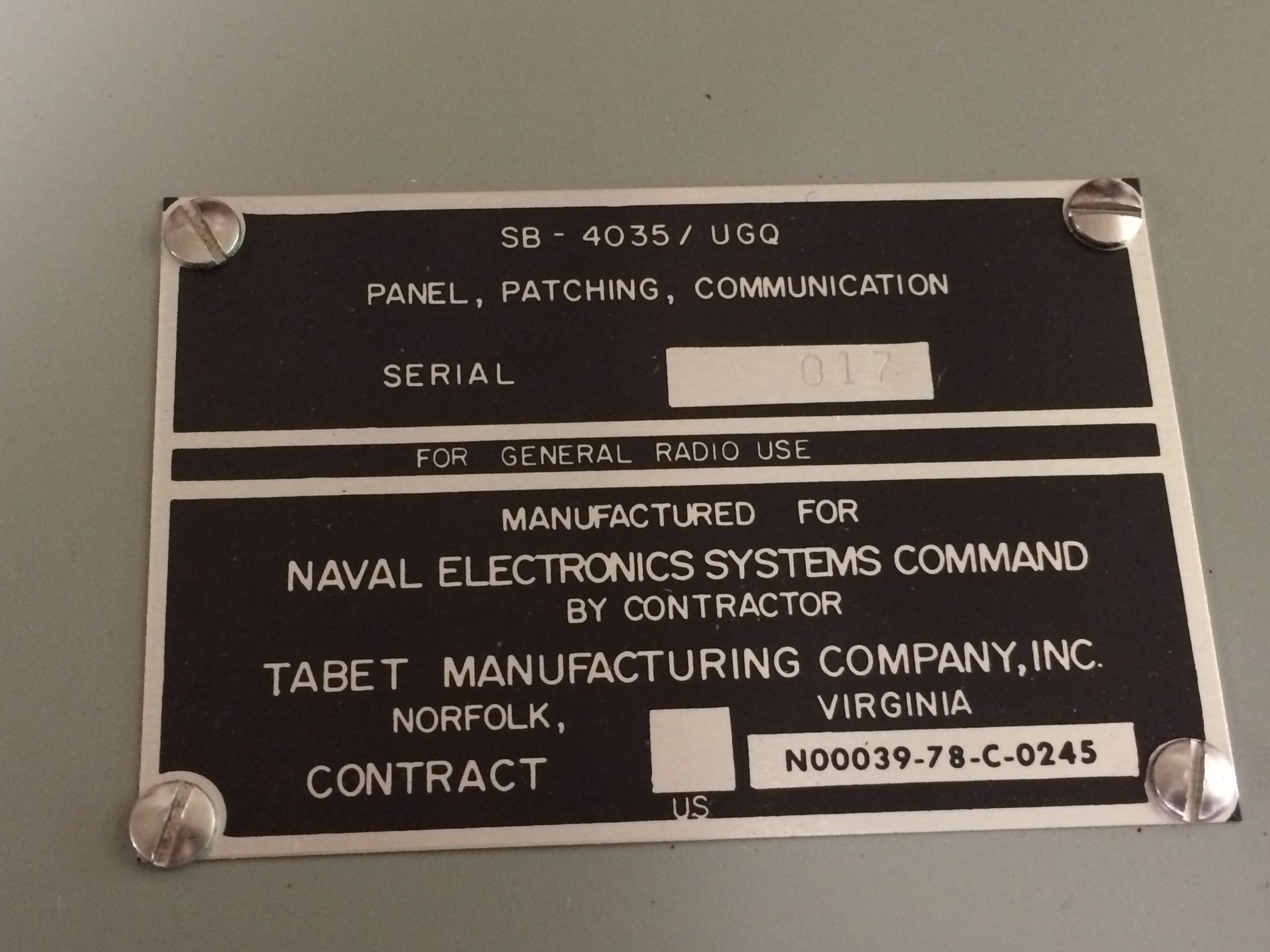
Unstamped but a typical USN ID plate
|
and USN inspection stamp

|
|
|
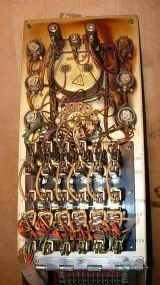
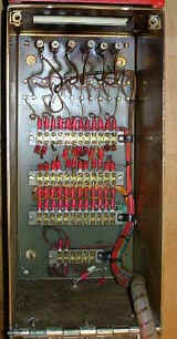
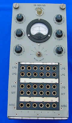
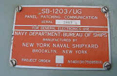
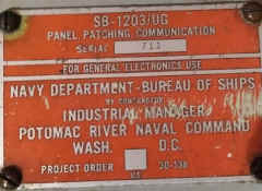
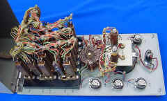
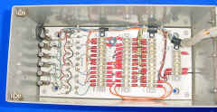
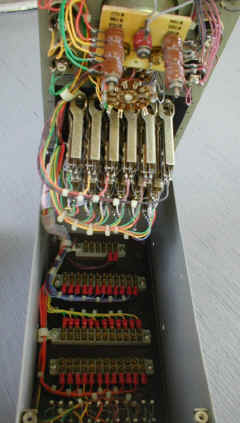
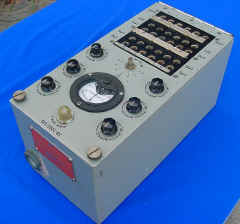
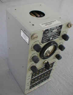
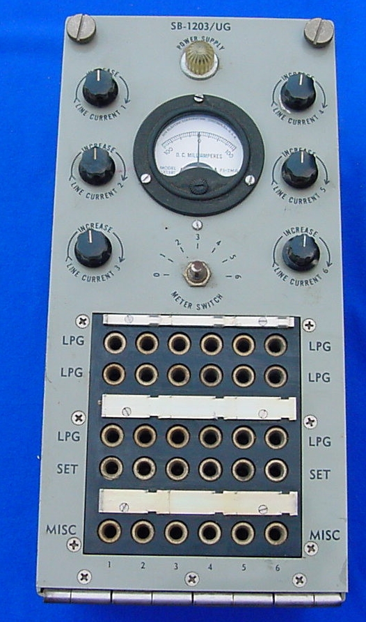
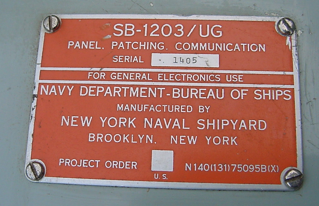
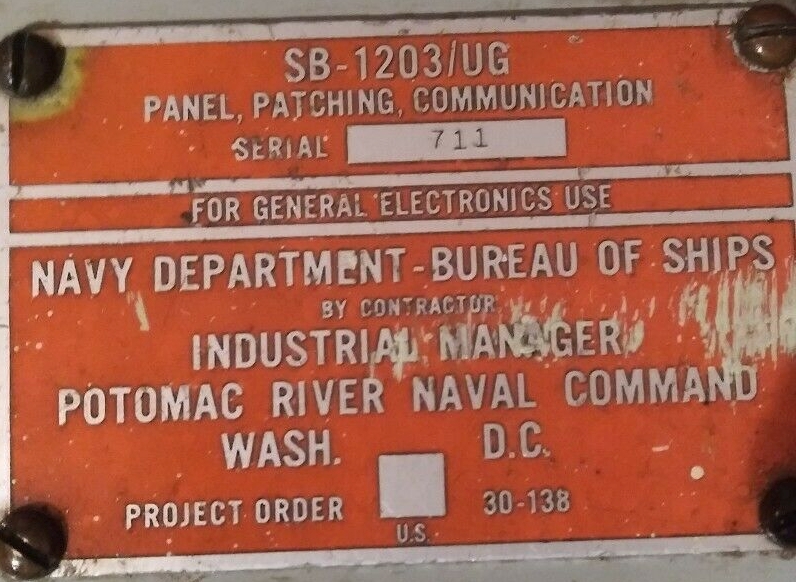
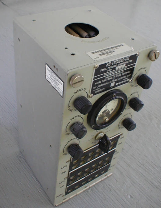
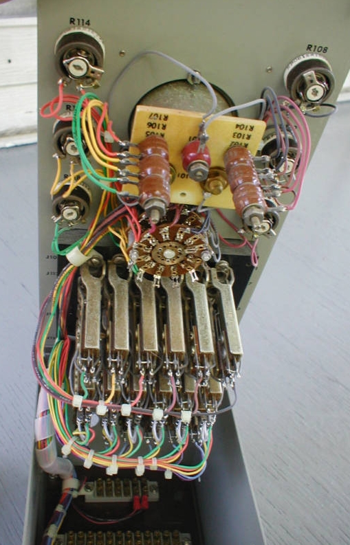
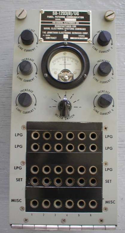
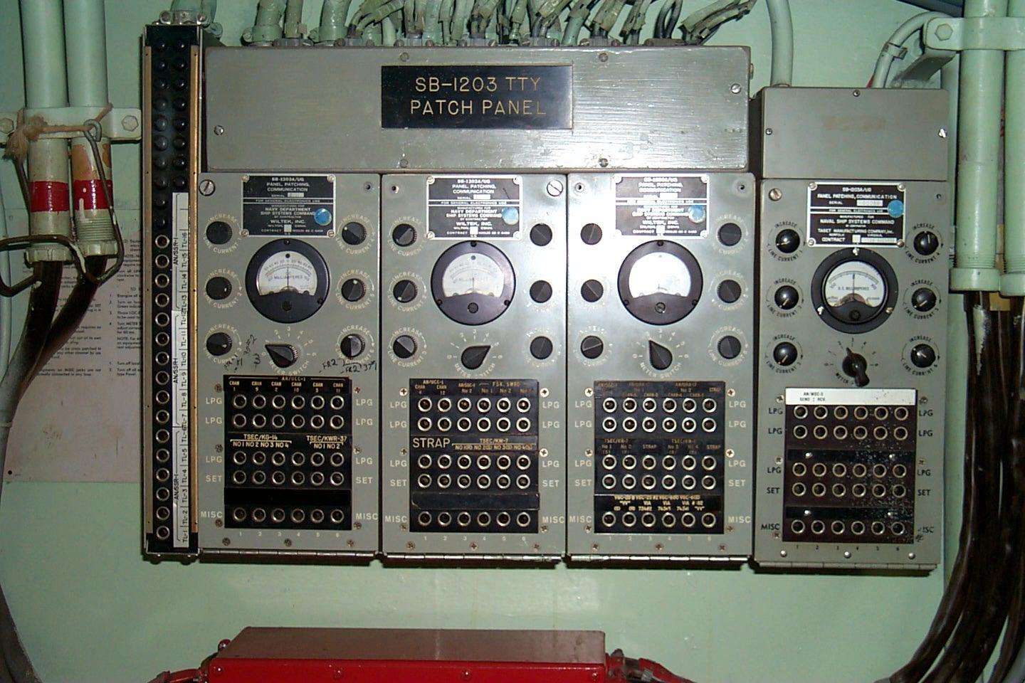
SB-1203/UG
SB-1203A/UG
SB-1203B/UG
SB-1203A aboard USS Midway
|
6 channels
3 LPG, 1 SET, 1 MISC
|
|
More info - schematics, connections,
operation, etc.
SB-1203/UG is for black (unclassified) circuits
manual -
NAVSHIPS 95718
|
|
|
|

|
|

|
|
|
==
|
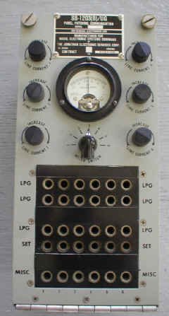
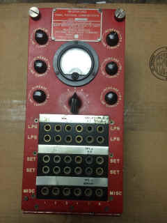
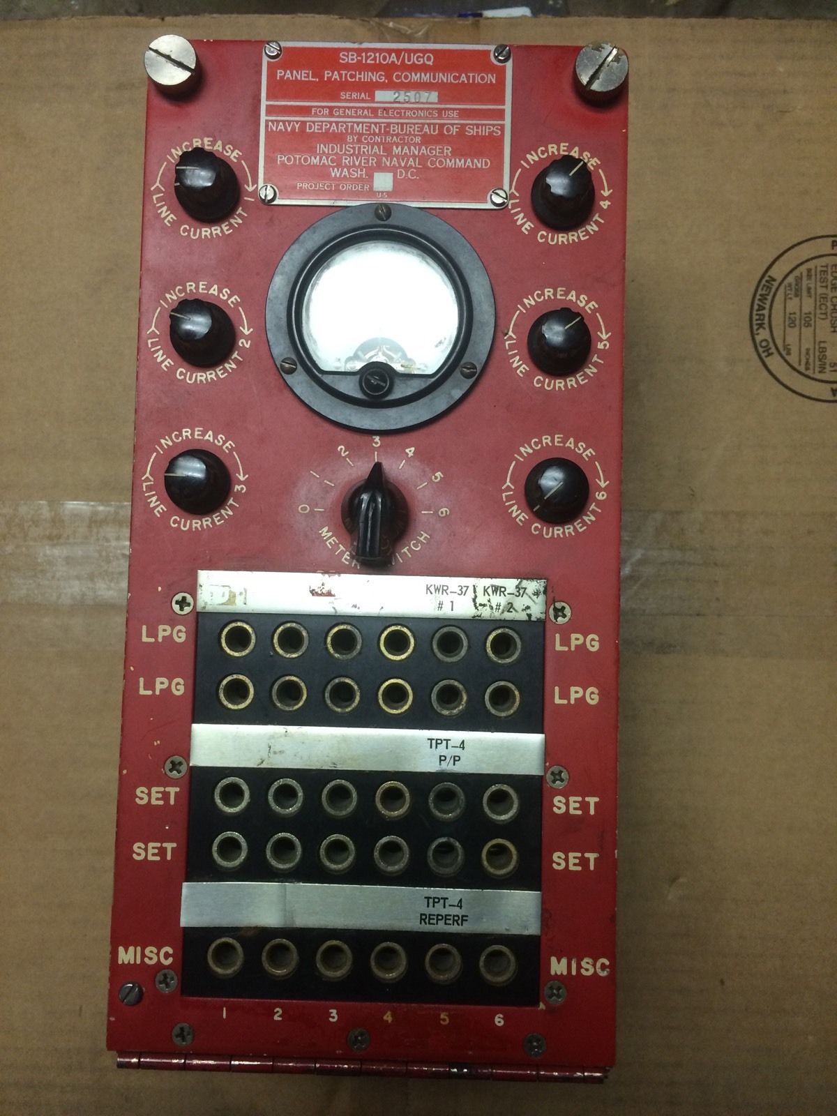
SB-1210/UGQ
SB-1210A/UGQ
SB-1210B/UGQ
|
6 channels
2 LPG, 2 SET, 1 MISC
|
 |
More info - schematics, connections,
operation, etc.
SB-1210/UGQ is for red (classified) circuits.
manual -
NAVSHIPS 95718
SB-1210 aboard USS Midway
|
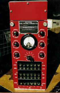
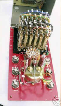
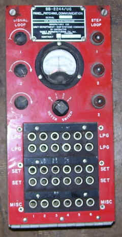
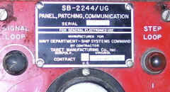
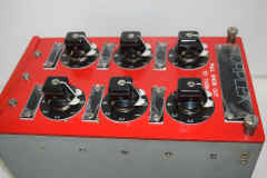
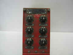
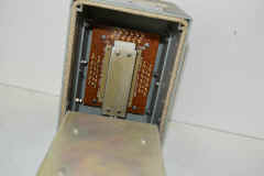
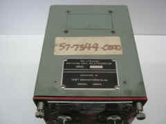
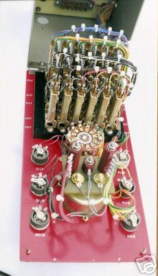
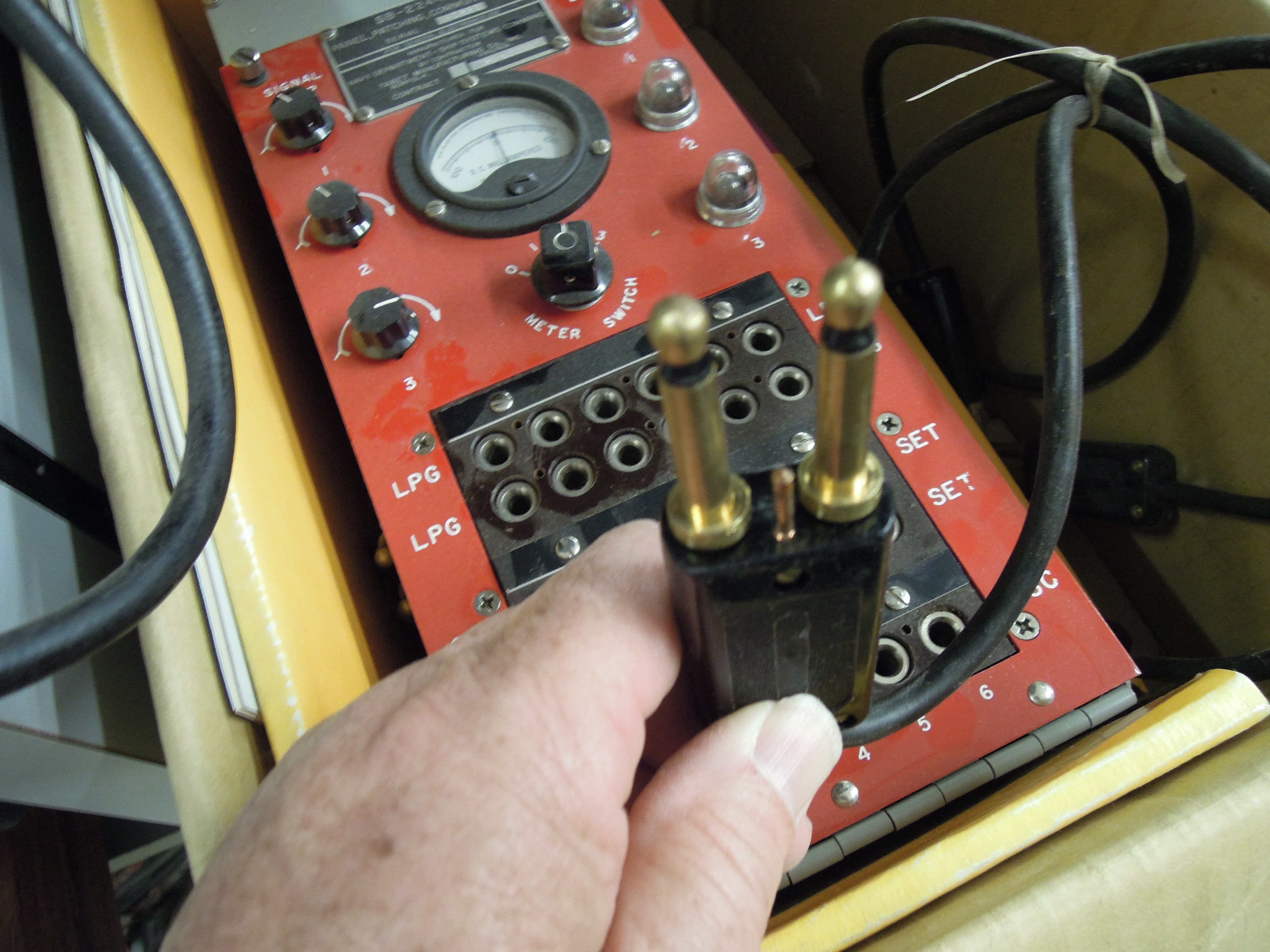
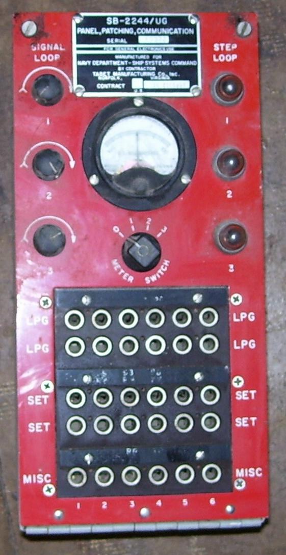
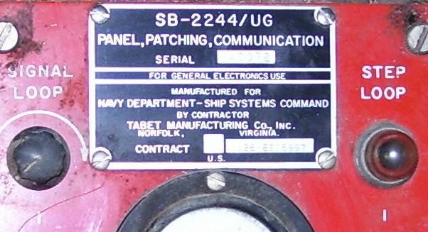
SB-2244/UG
for crypto equipment with step control of TTY tape reader.
NAVSHIPS 91622 manual
- thanks to Don N3RHT
|
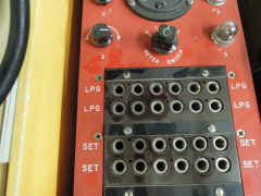
3 dual channels
2 LPG, 2 SET, 1 MISC
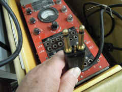
The special patch cords are dual cords with a pin that matches the hole between
the jacks - this prevents getting TTY and STEP signals crossed.
Channels 1,3,5 have TTY current control and metering - Channels 2,4,6 have
associated
"STEP LOOP" indicators. The STEP signal releases the
next character from a TD under timing control of the crypto gear.
|
|
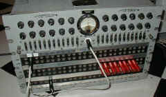
Note - as of 5/2016 Fair Radio has this one unused in the box for sale
- with manual and patch cords.
|
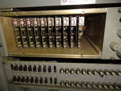
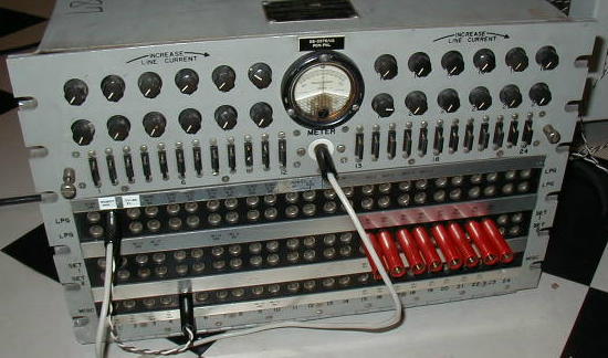
SB-3576/UG
24 channels
2 LPG, 2 SET, 1 MISC
|
 |
includes fuses and alarm bell to indicate blown fuse
|
== |
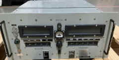
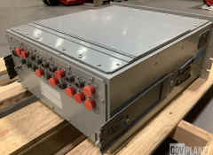
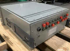
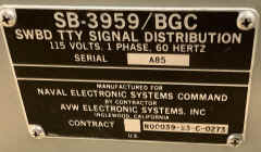
SB-3939/BGC
Probably low-level
for submarine use?
|
 |
|
 |
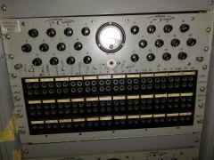
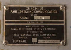
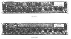
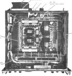
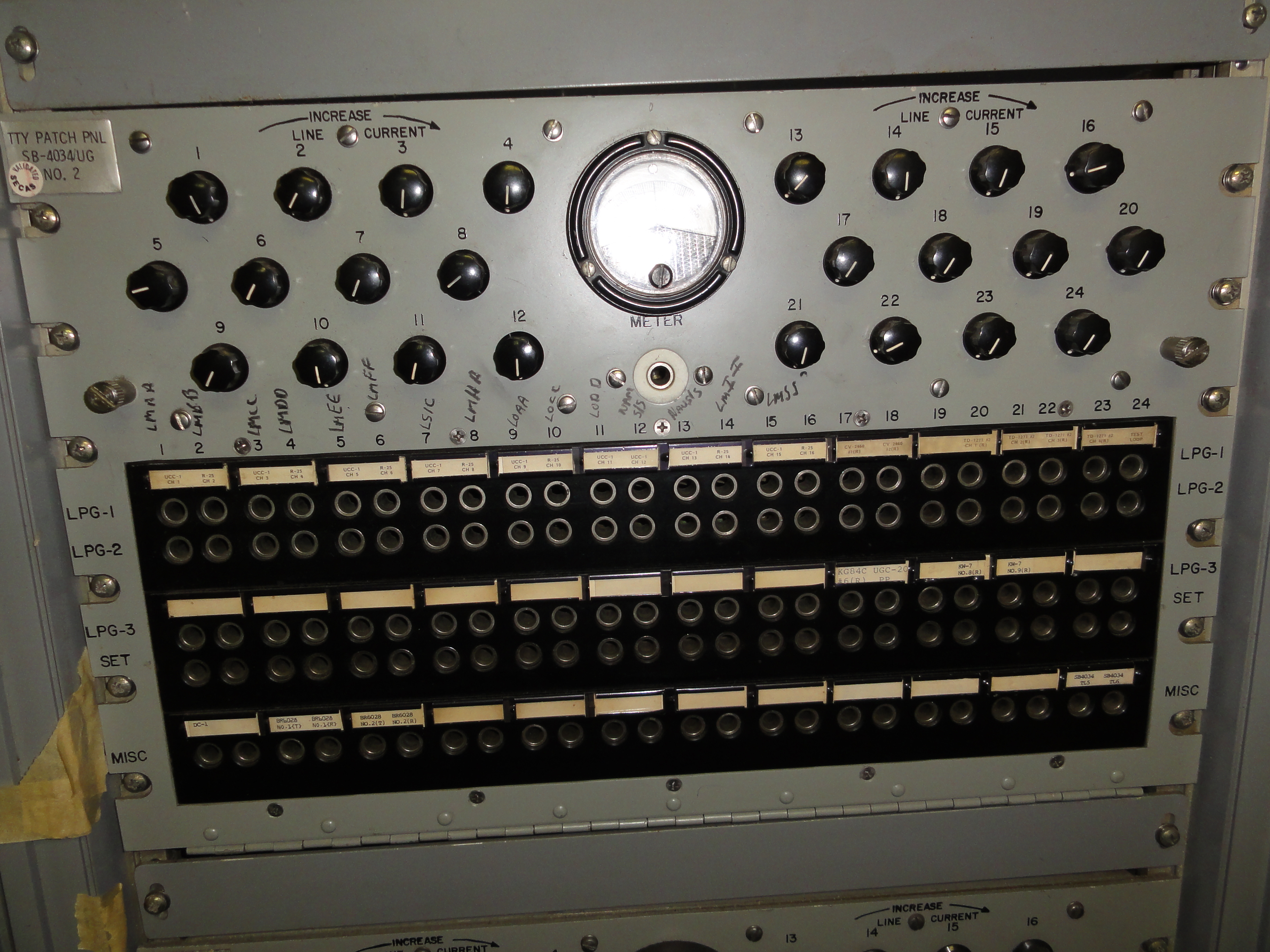
SB-4034/UG
24 channels
2 LPG, 2 SET, 1 MISC
|
SB-4034 aboard USS Iowa
 |
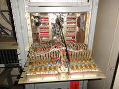
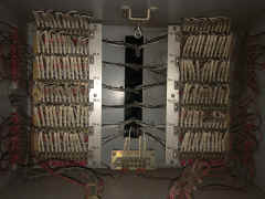
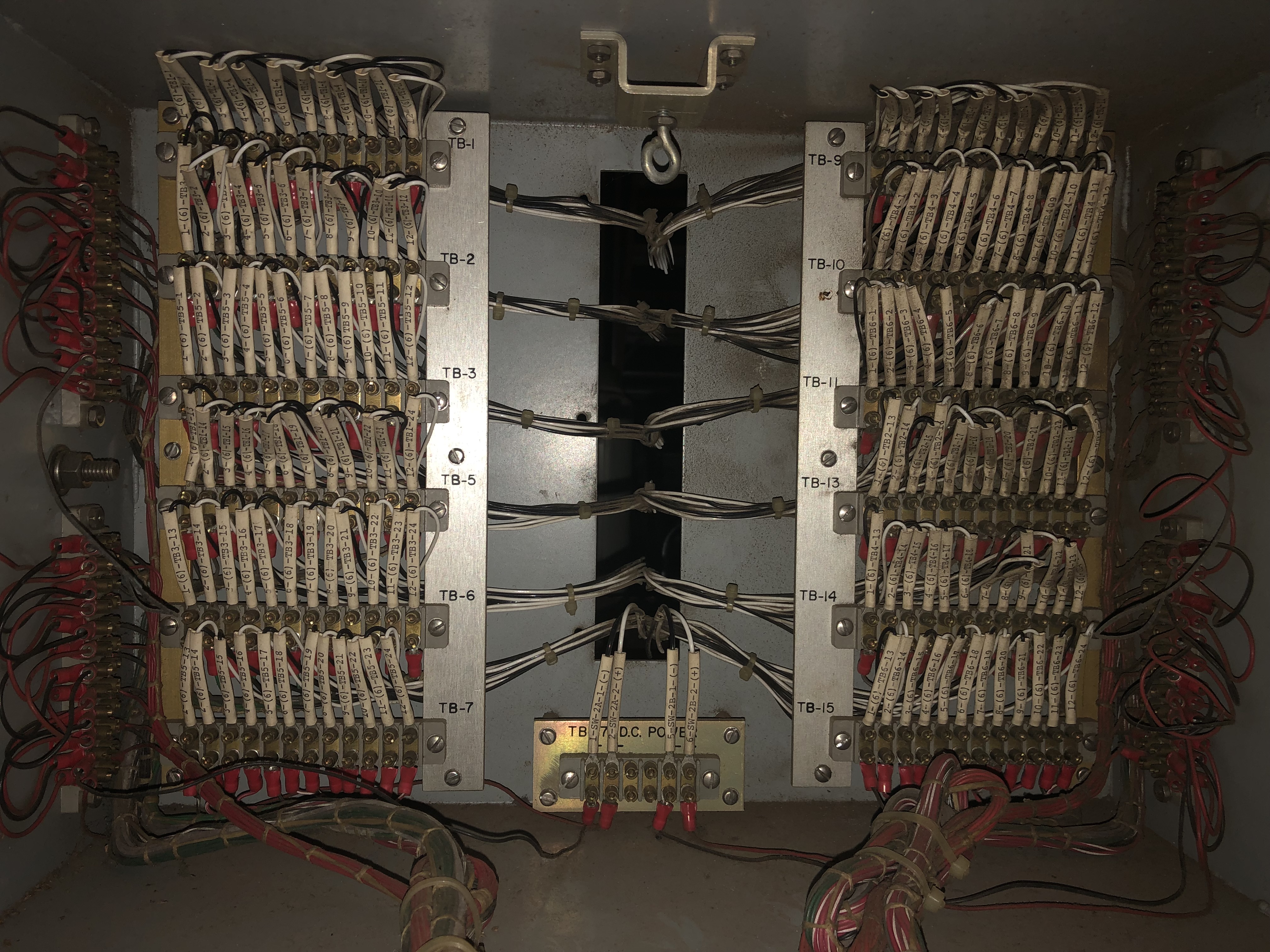
SB-4034/UG interior
|
 |
|
 |
|
== |
|
 |
|
== |
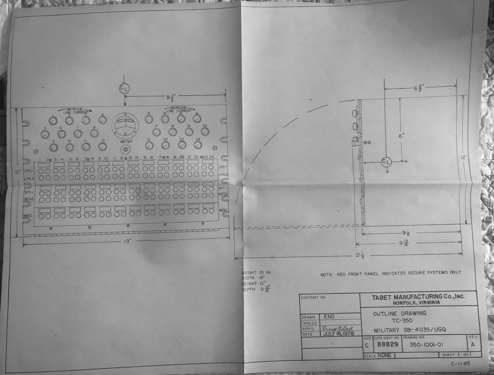
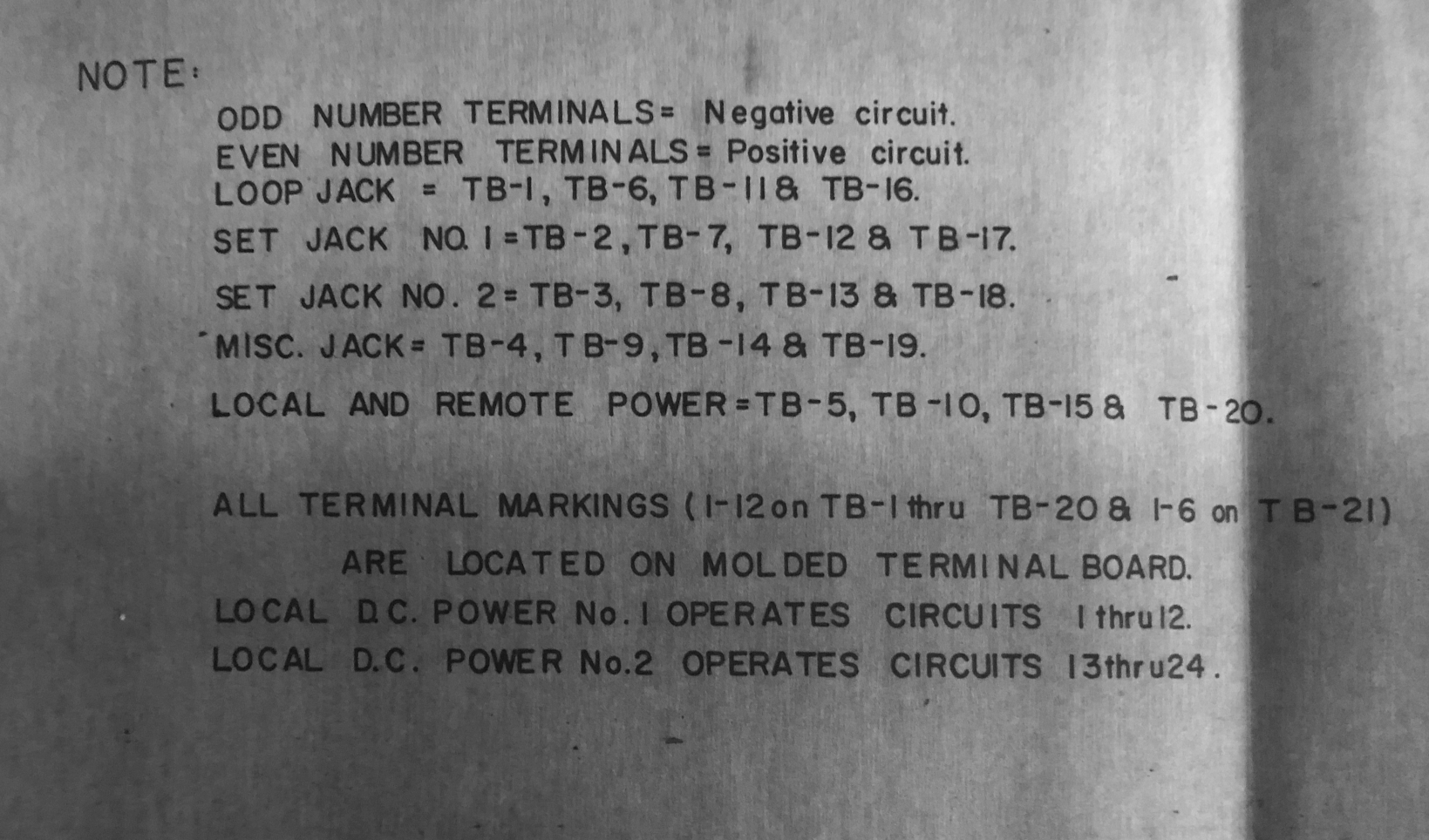
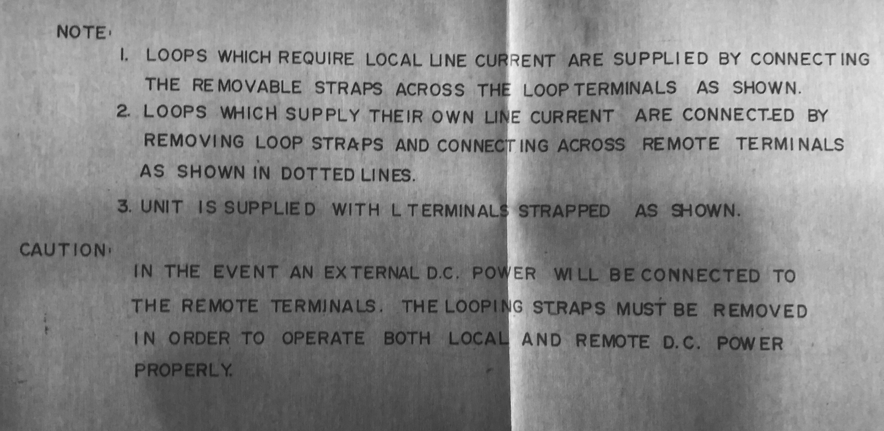
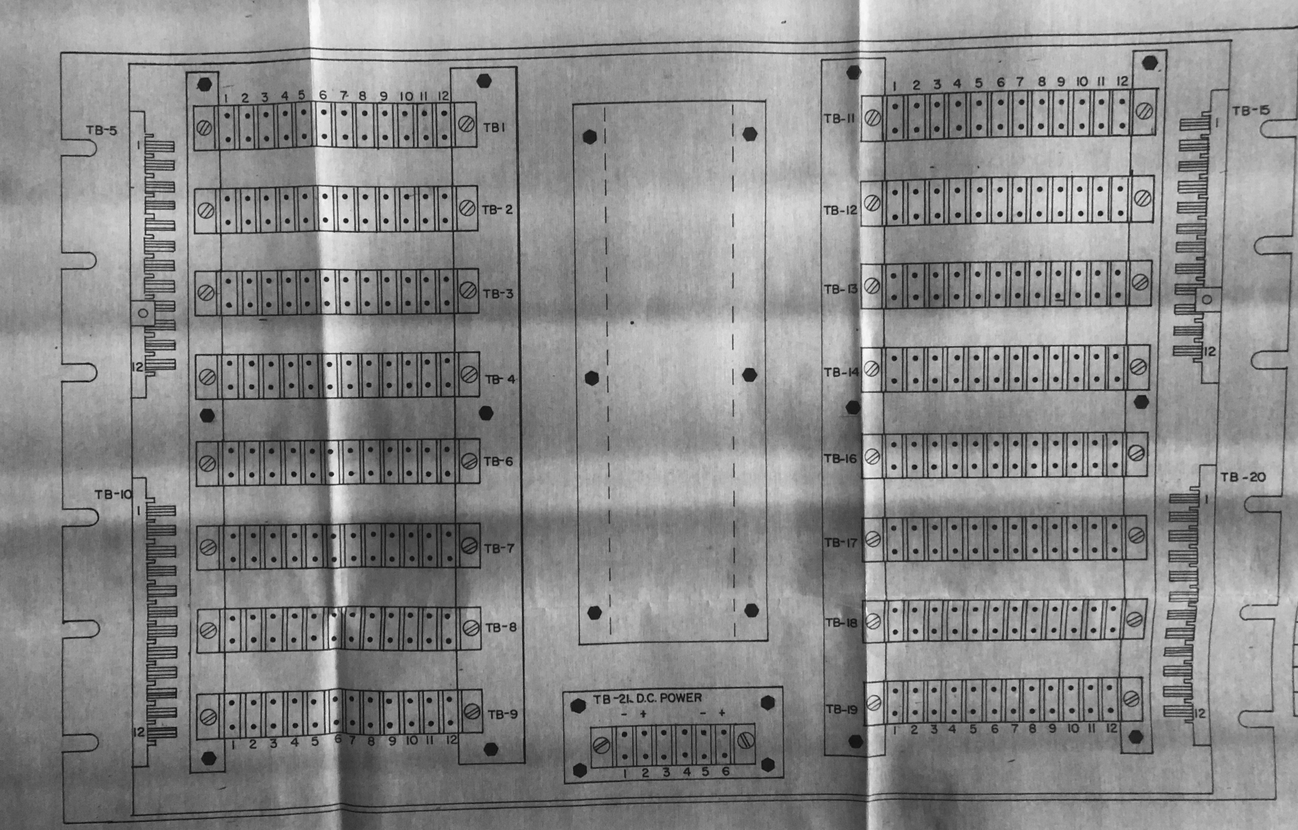
SB-4035/UGQ
24 channels
2 LPG, 2 SET, 1 MISC
|
 |

|

|

|
 |
|
|
|
|
|
|

|

|
|
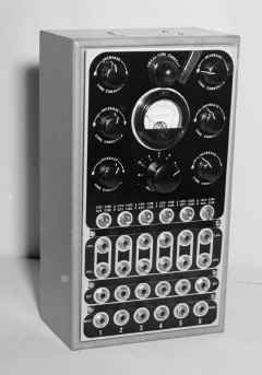
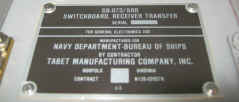
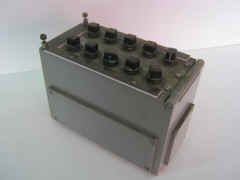
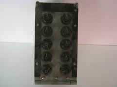
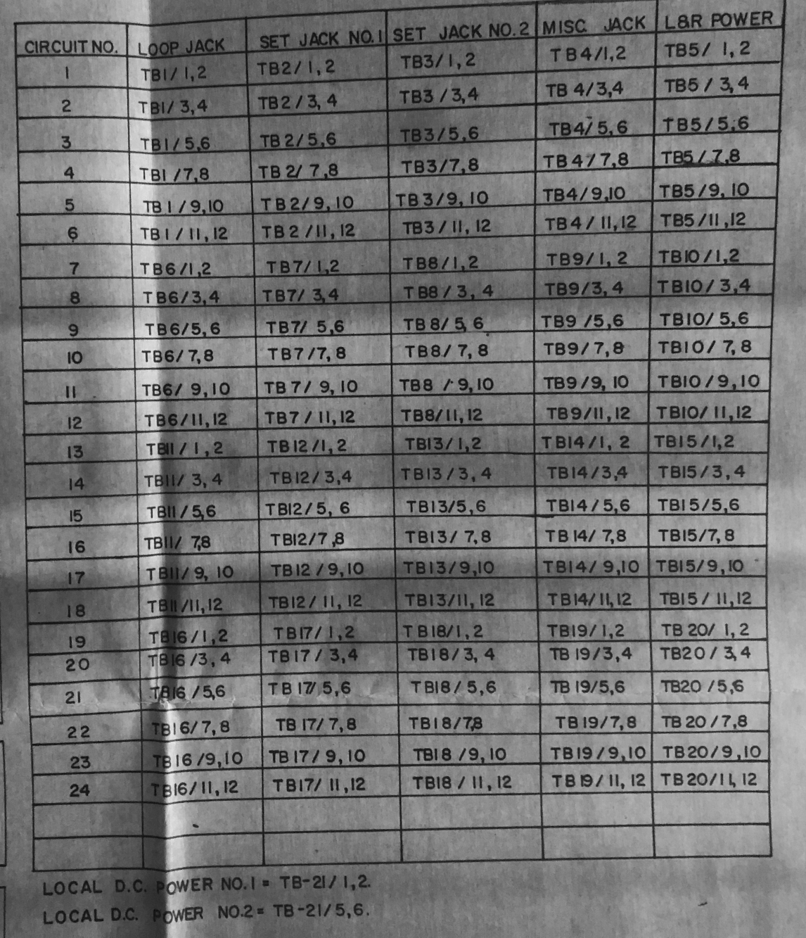
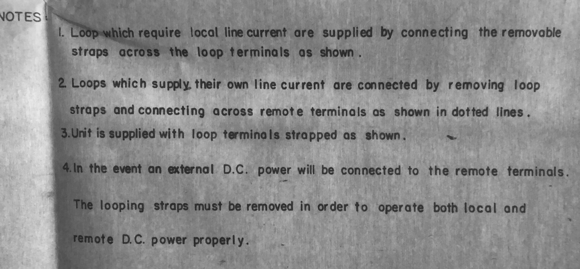
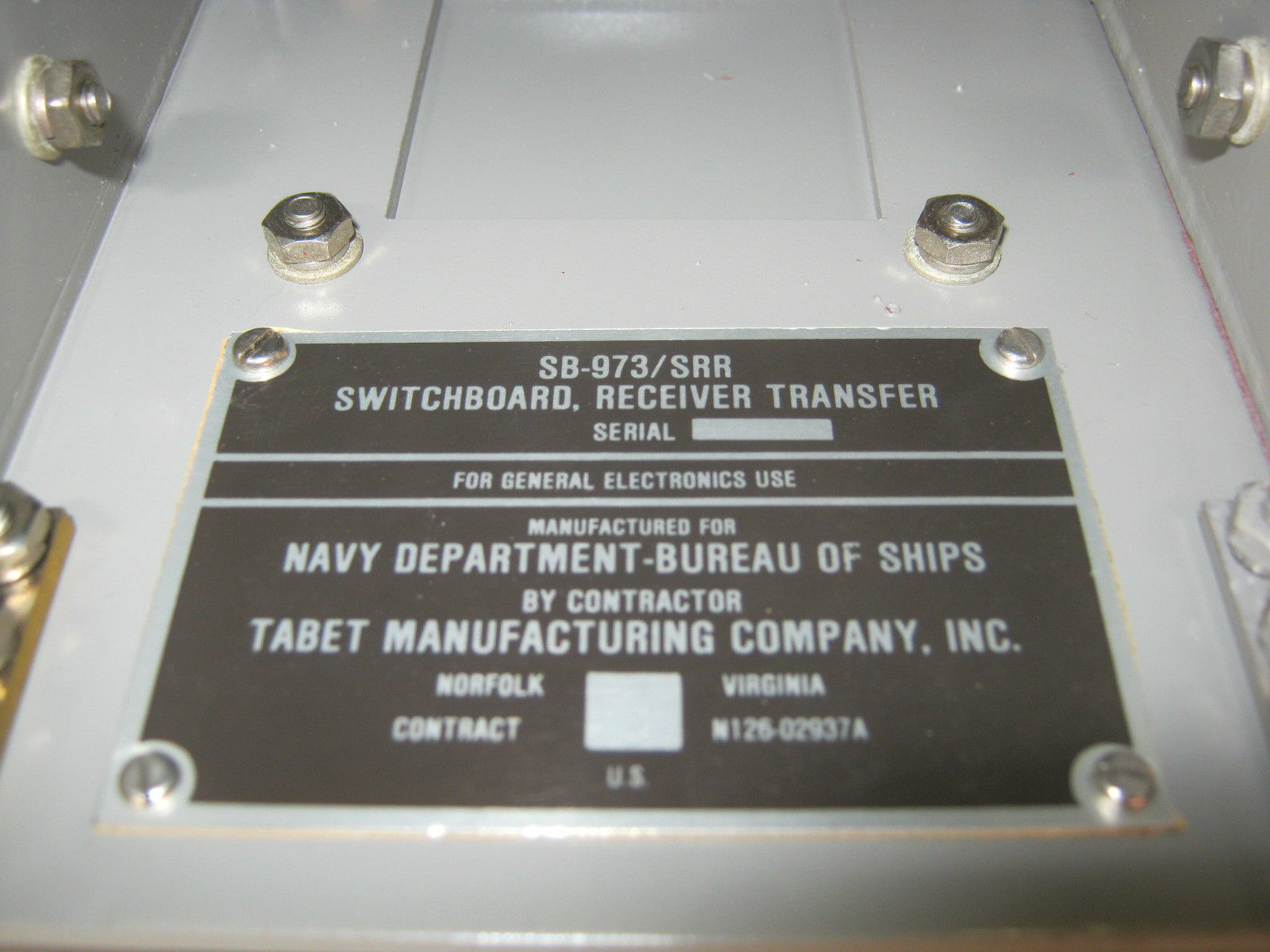
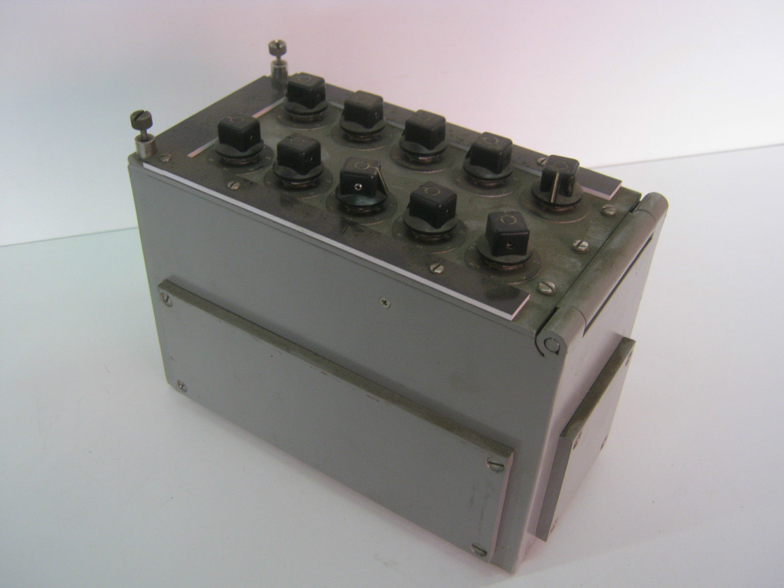
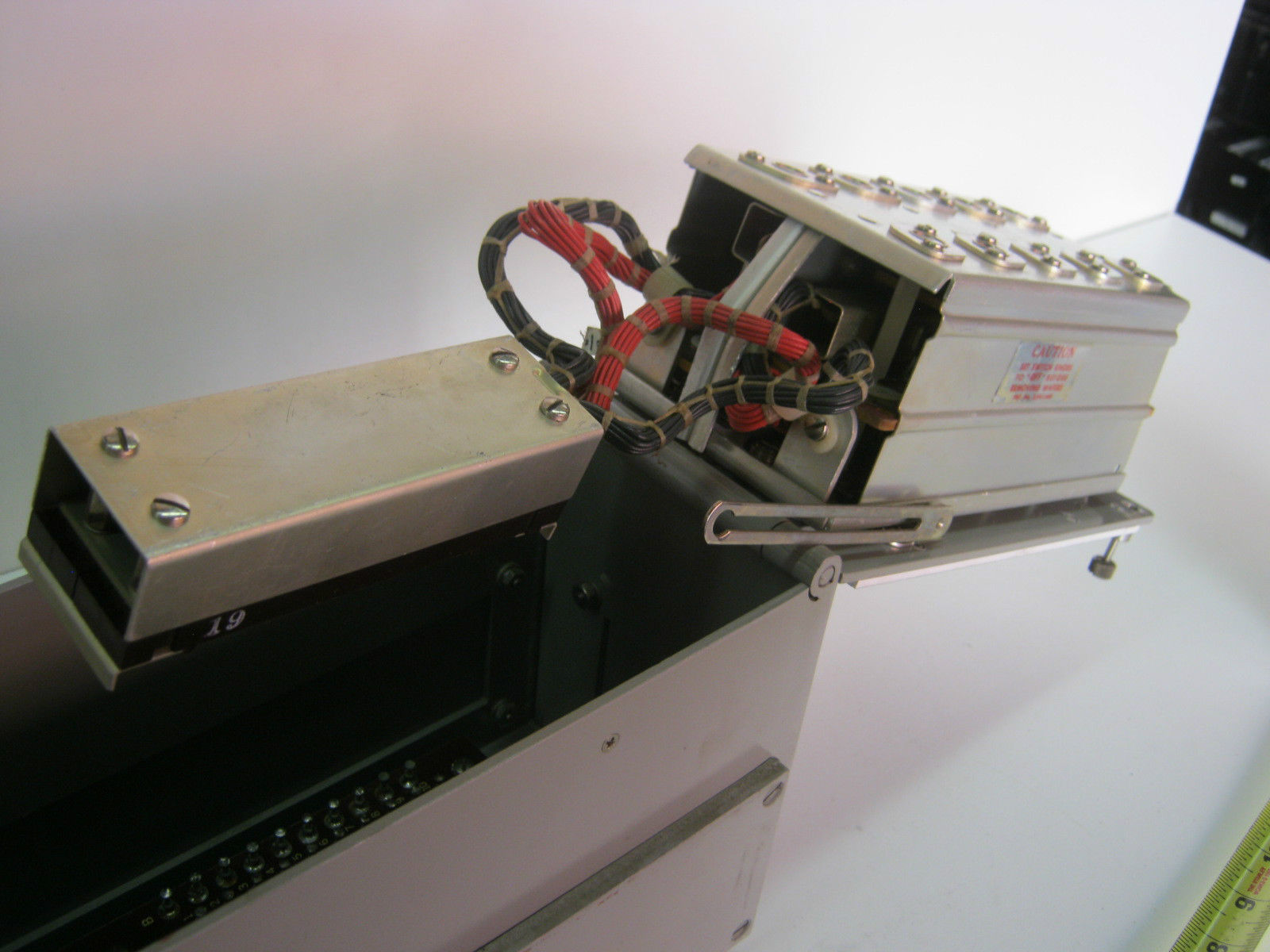
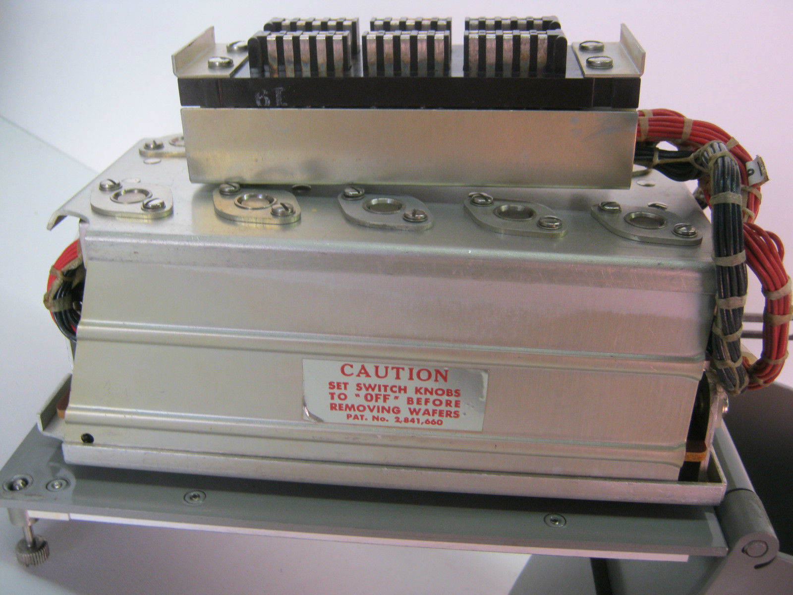
SB-973/SRR High-level switchboard
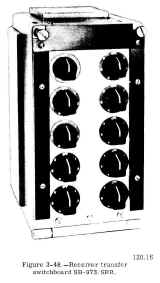 |
This switchboard is usually used for receiver audio, but
also be used for high-level TTY lines.
|
|
|
 |
|
|
|
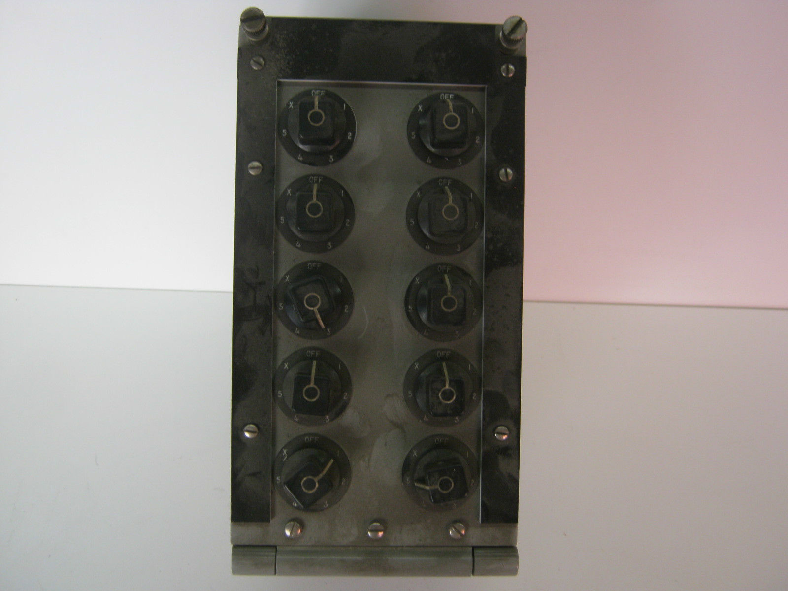
SB-973/SRR - switching - 10 two-wire
TTY lines, 5 transmitters - (SB-973 is usually used for switching receiver
audio lines)
This switchboard contains 10 seven
position rotary selector switches. Each switch or operating knob relates
to a TTY line Switch positions one through five relate to
transmitters. Position X on each switch serves to transfer the TTY
lines connected to the original switchboard to the
corresponding switches in additional switchboards.
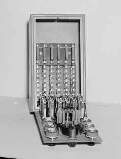
Switchboards providing facilities for additional
transmitters are mounted in vertical sequence, whereas those
containing additional TTY lines are mounted in horizontal sequence. |
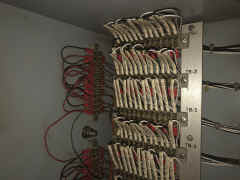
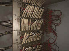
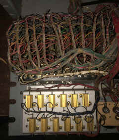
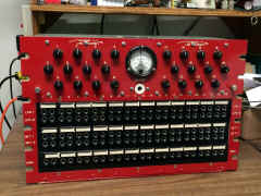
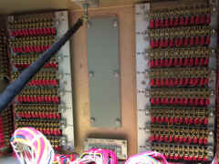
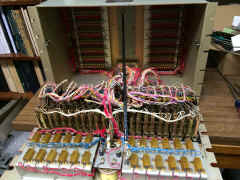
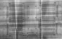
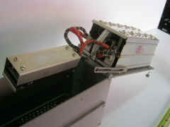
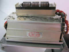
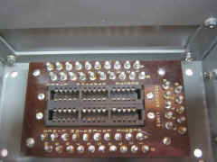
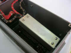
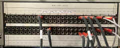
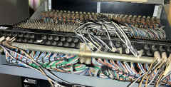
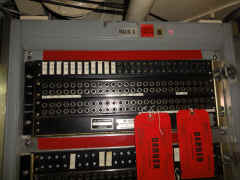
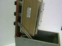
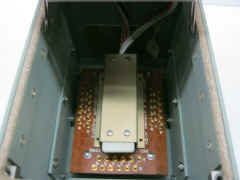
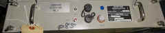
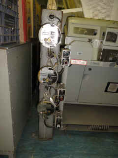
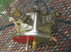
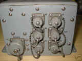
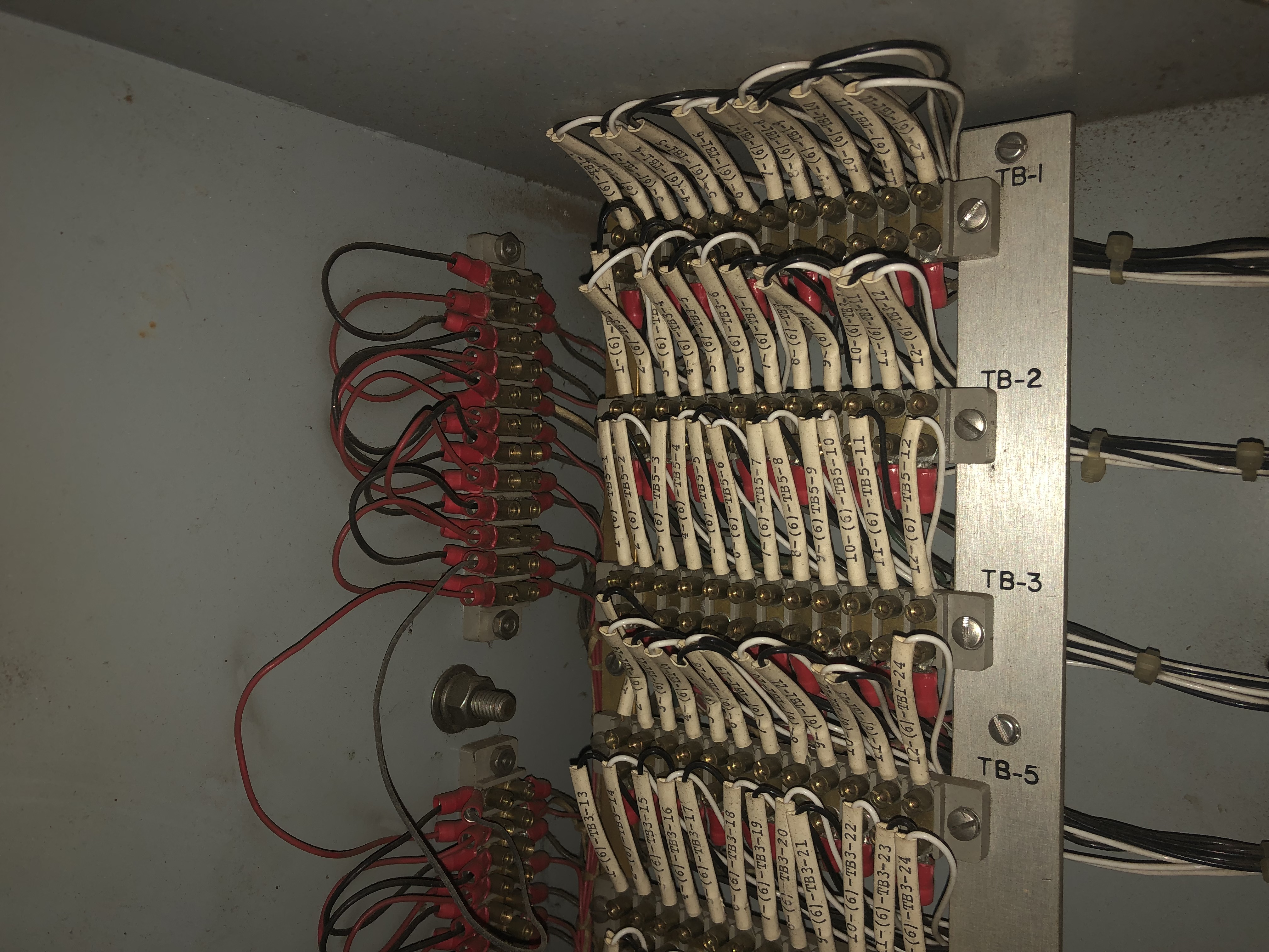
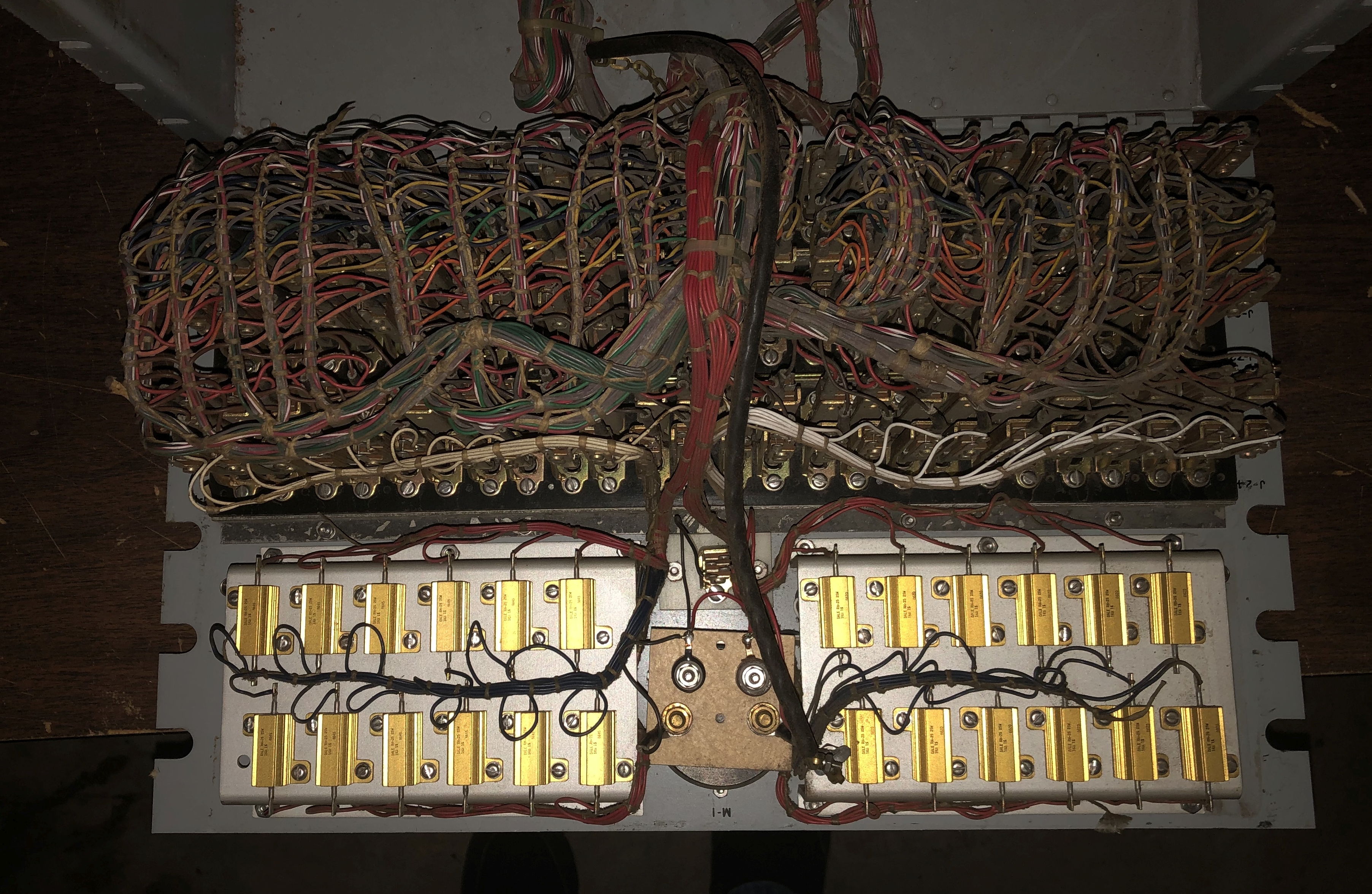
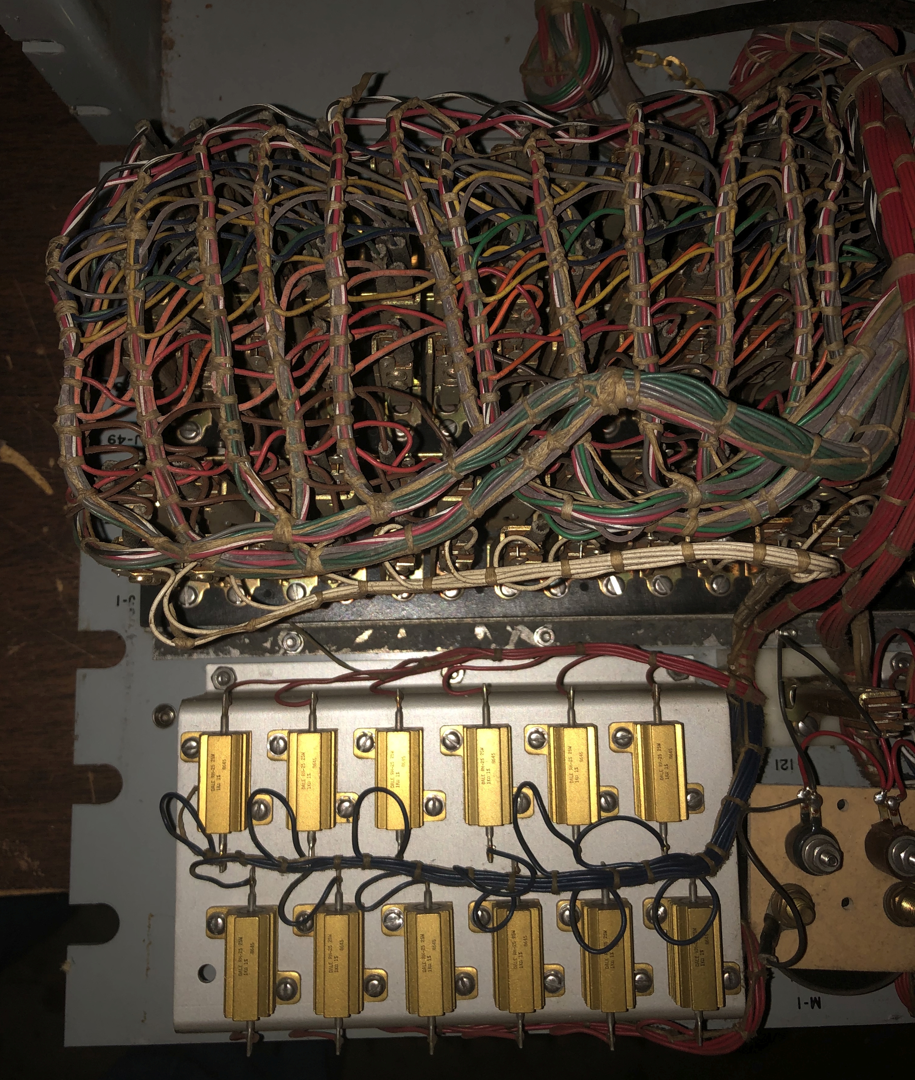
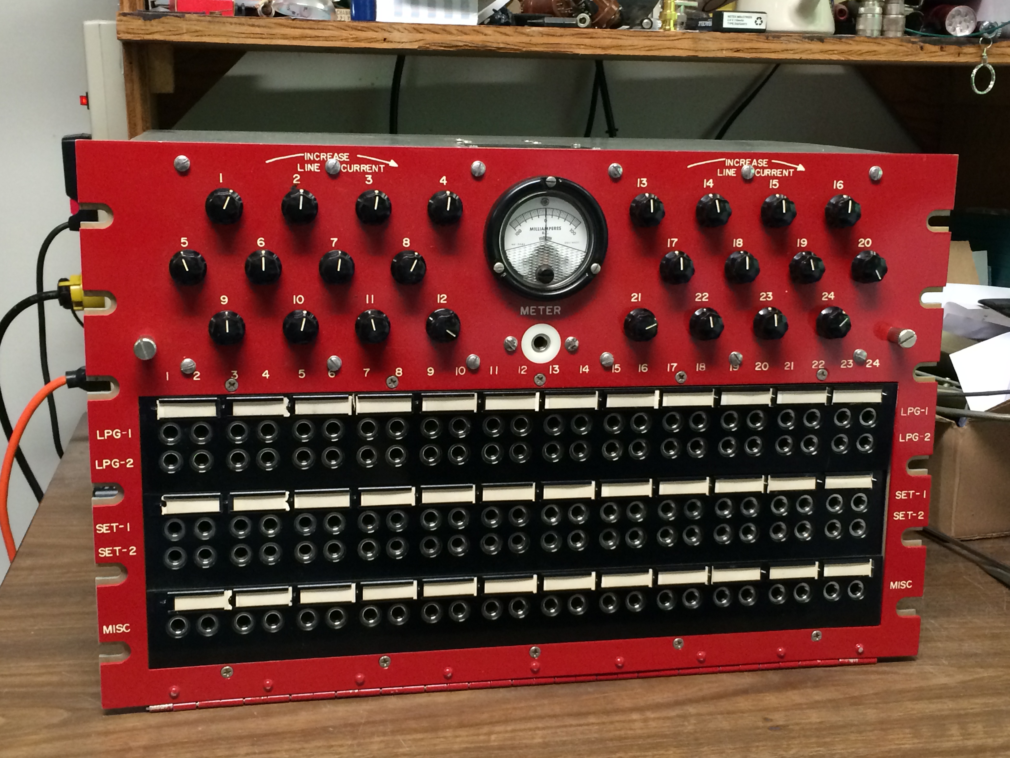
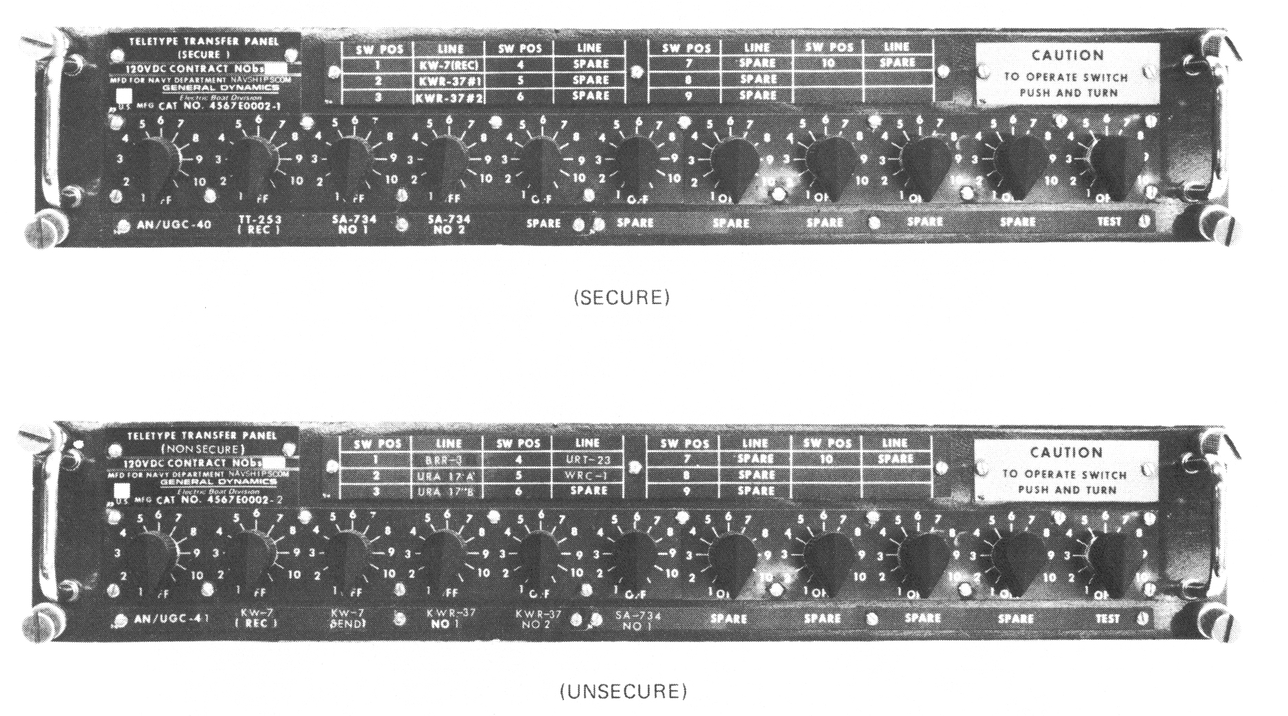
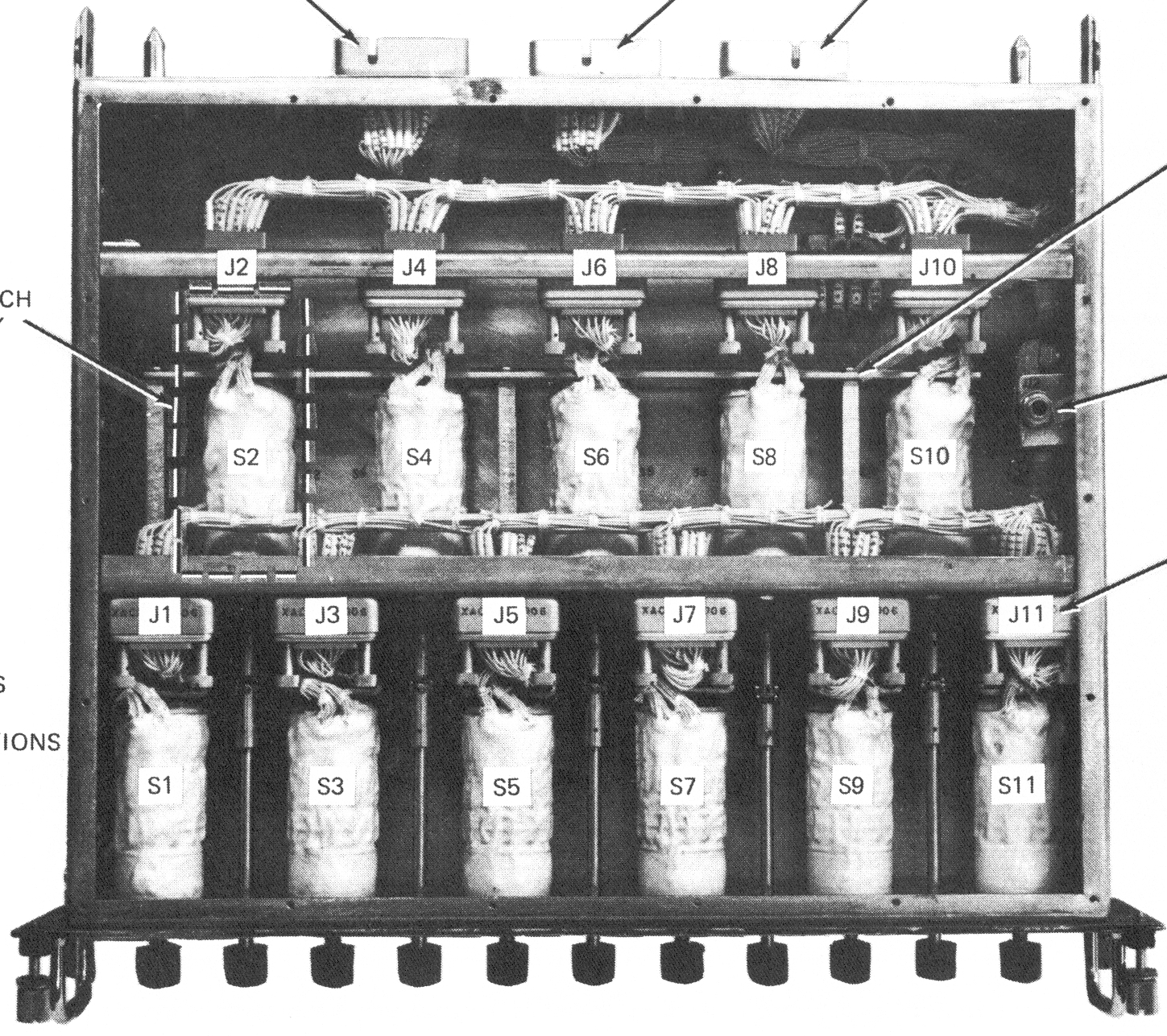
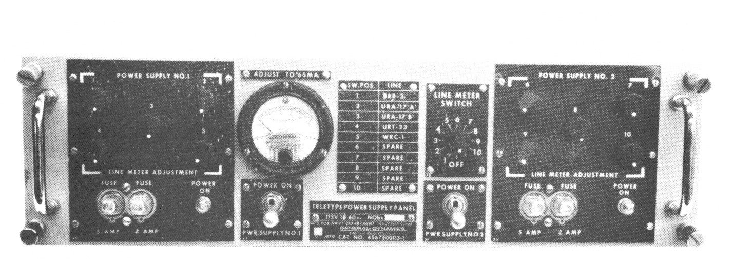
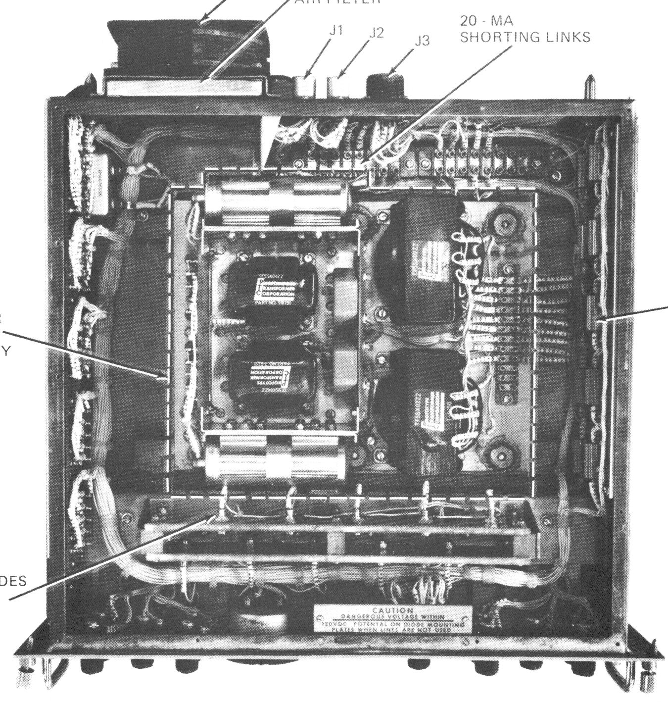
Teletype Transfer and Power Supply Panels for SSN637 Class Submarines
|
10 input to 10 output Switch Panels -
Secure (Red) and Unsecure (Black)
|
 |
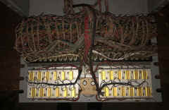
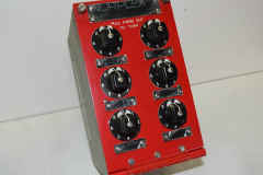
Dual Power Supply with Loop Current Adjust
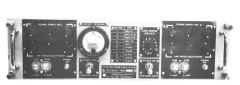
|
 |
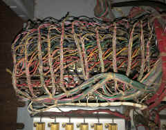
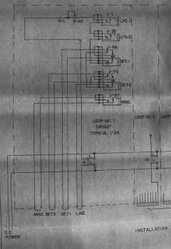
Low Level (+/- 6v) Patch Panels & Switching Unit
|
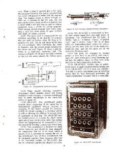
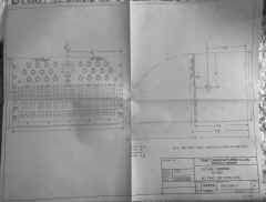
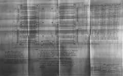
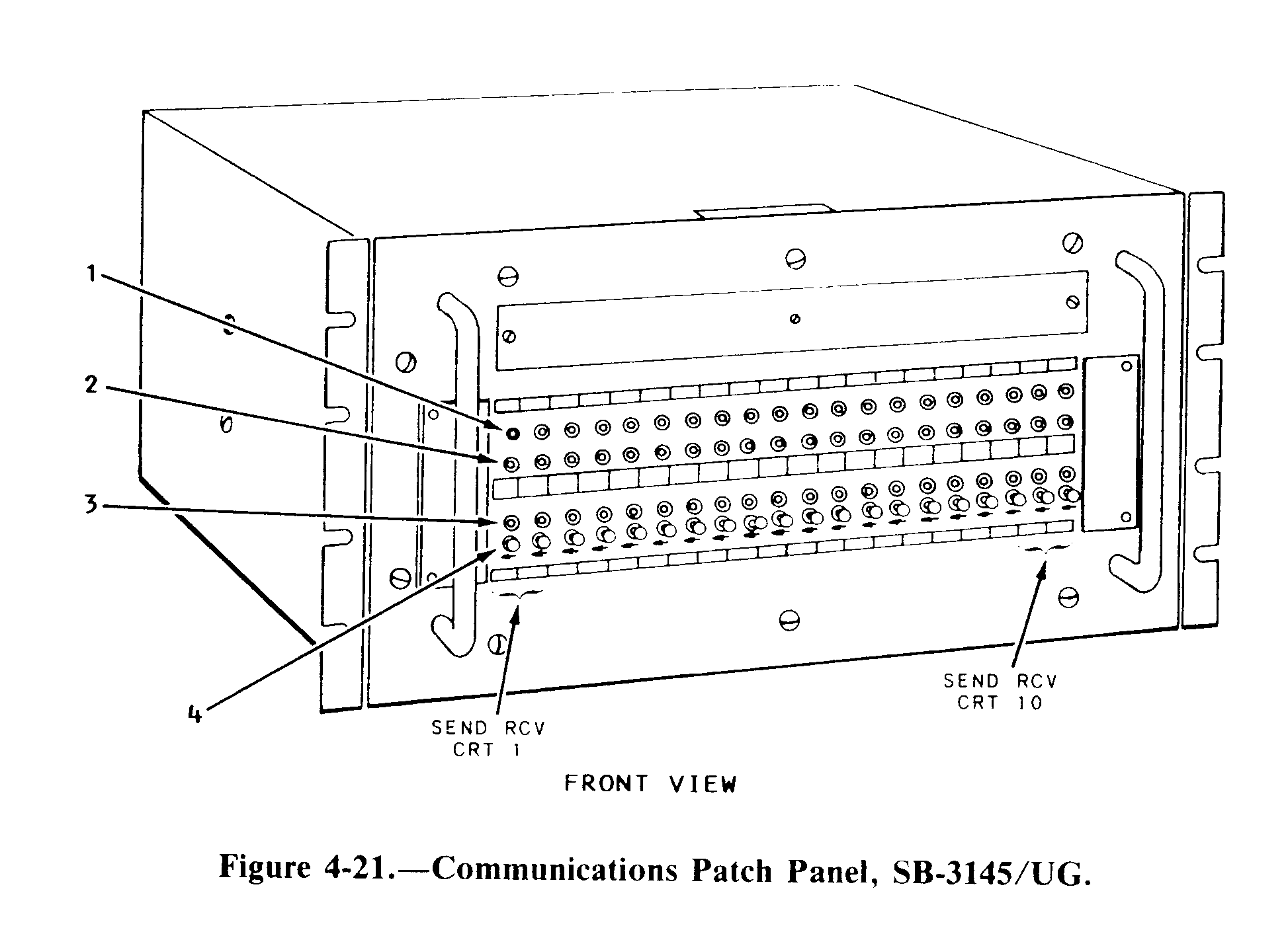
SB-3145/UG
|
COMMUNICATIONS
PATCH PANEL,
SB-3145/UG - This
communications patch panel is a low-level, send-and-receive
teletype, special-purpose patch
panel. It is capable of handling 20 half-duplex
or 10 full-duplex circuits. Figure 4-21 illustrates
the front panel. Jacks and controls are indexed
and referenced to descriptions listed in table
4-9. The panel is normally configured for
full-duplex, send-and-receive operation. The circuits
are numbered 1 through 10, with circuit 1
located on the left side of the panel and circuit 10
on the right side of the panel. Each circuit requires
two columns of jacks-one column for send
and the other for receive.
For Low-level signals (+/-6v) with 3-conductor patch cords (signals on ring & tip)
Installation drawings |
SB-3189/FGC
SB-3189A/FGC
SB-3189B/FGC
|
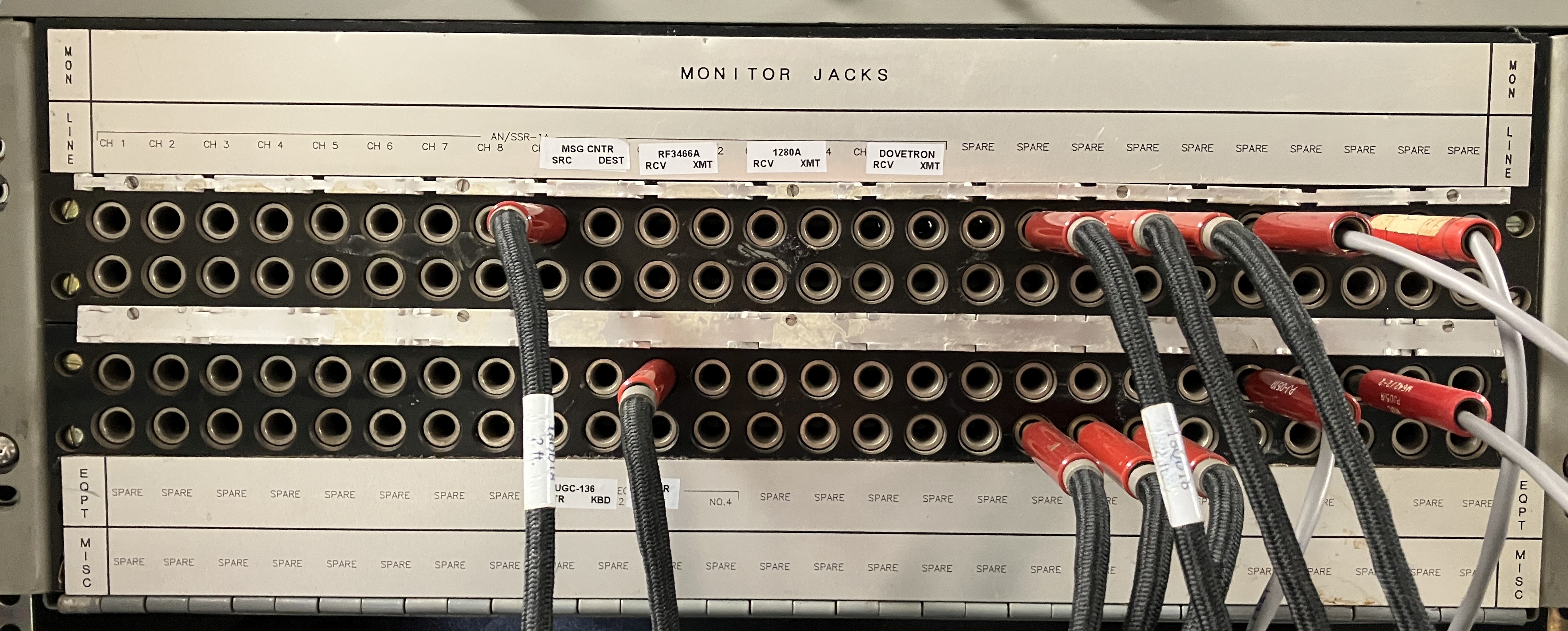
SB-3189/FGC
|
SB-3189B aboard USS Iowa
Secure (Red) TTY Patch Panel
 |
May be wired for Low-level (+/-6v)
or High-Level (60ma loop)
3-conductor patch cords
(signals on ring & tip)
Info in this manual
|
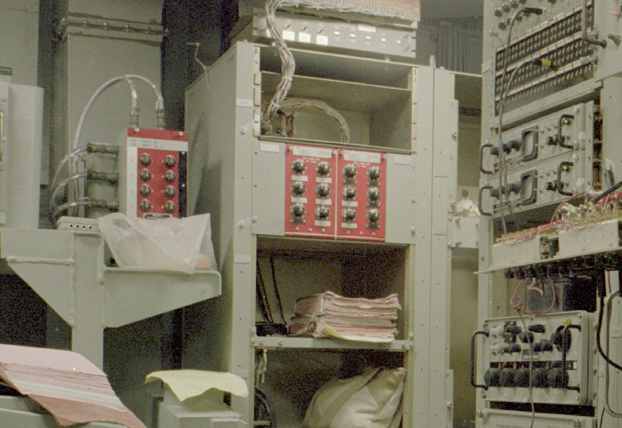
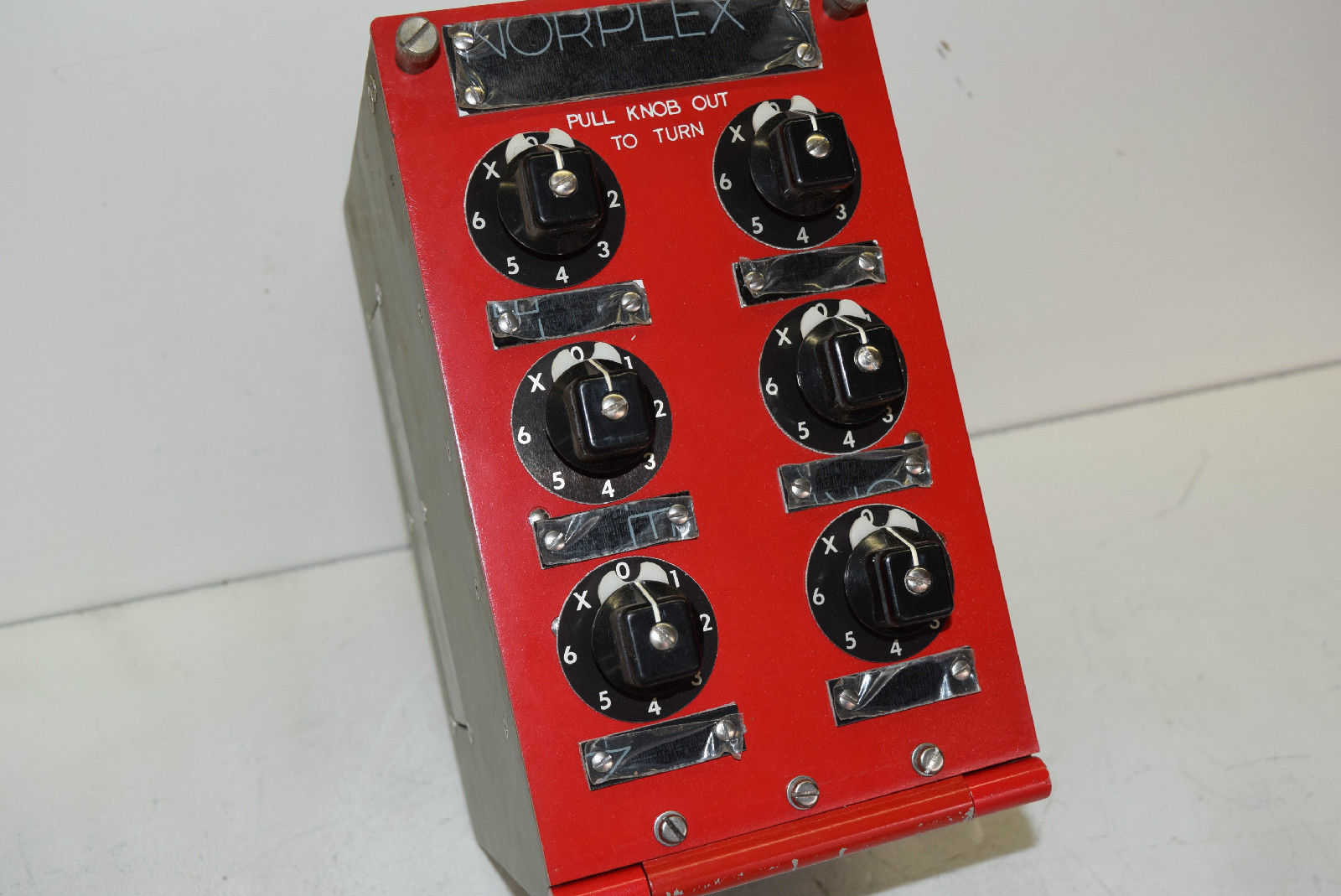
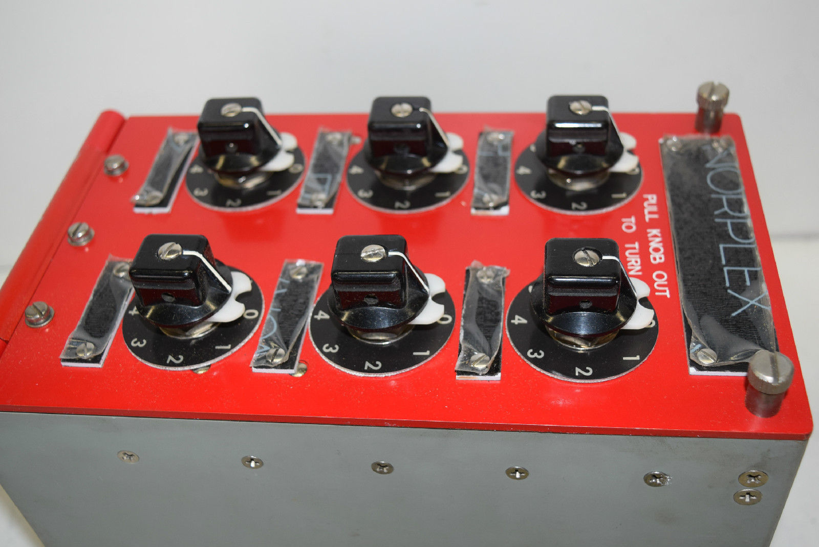
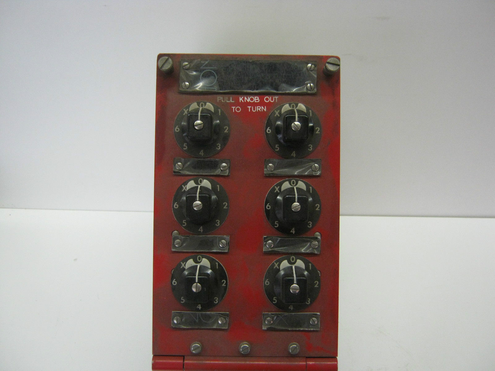
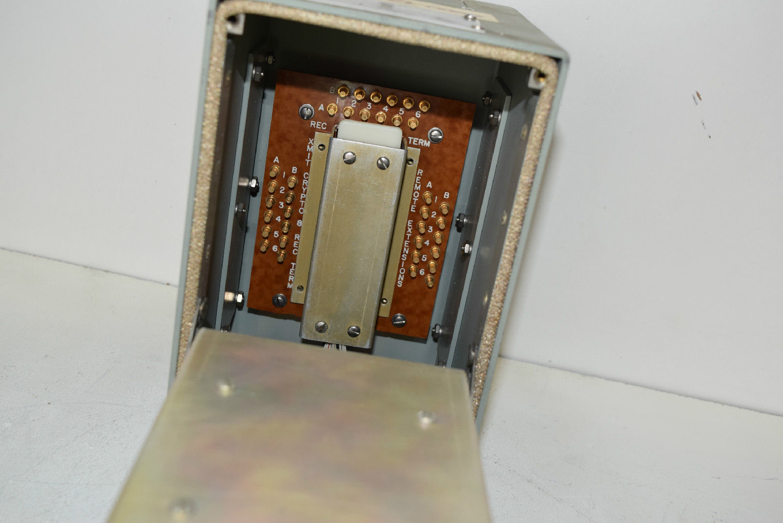
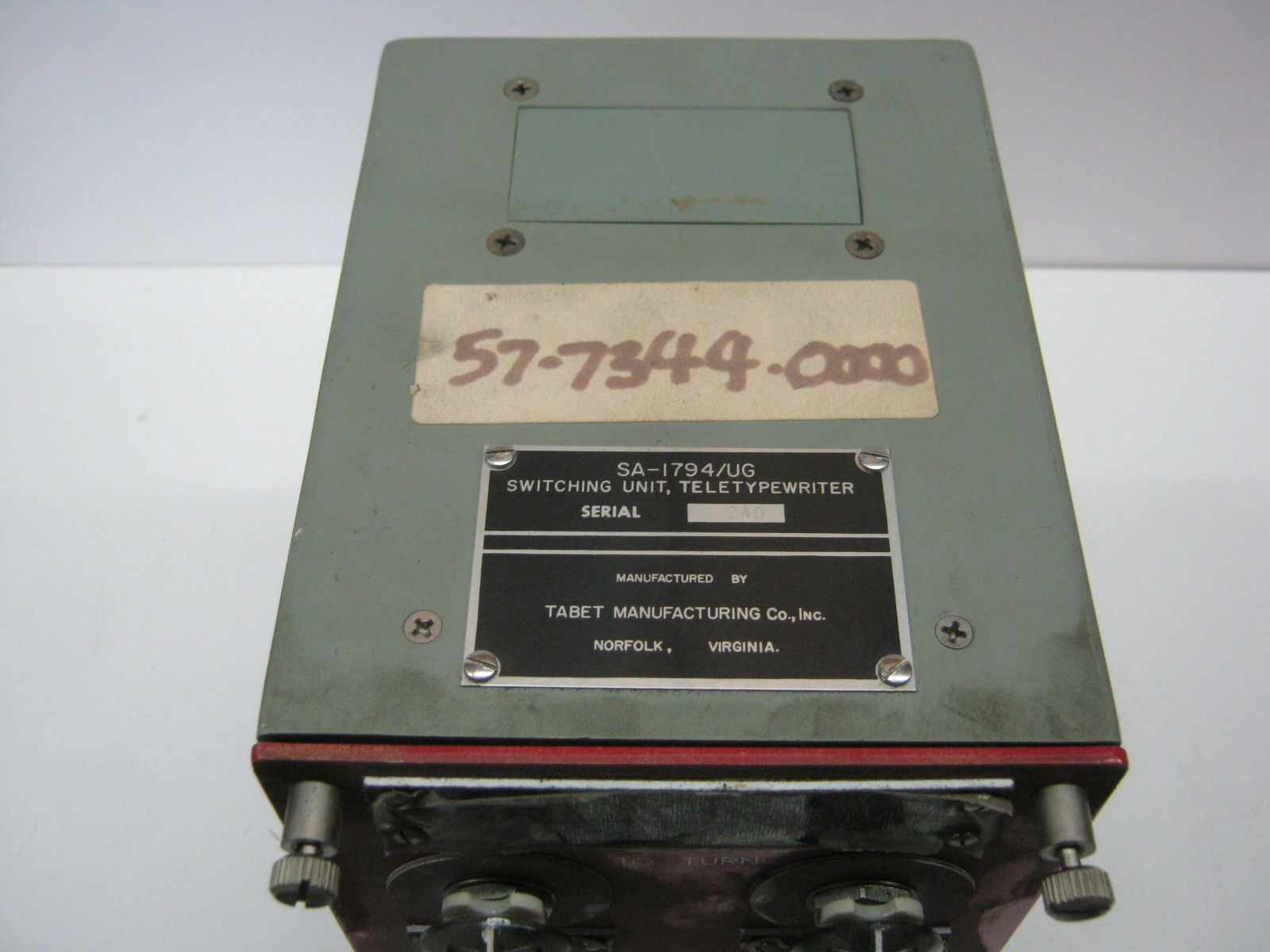
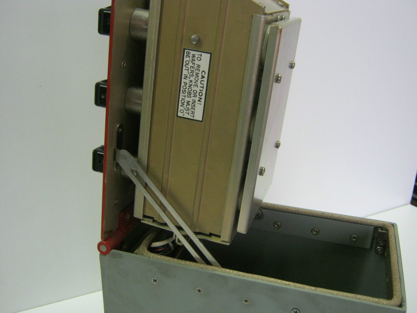
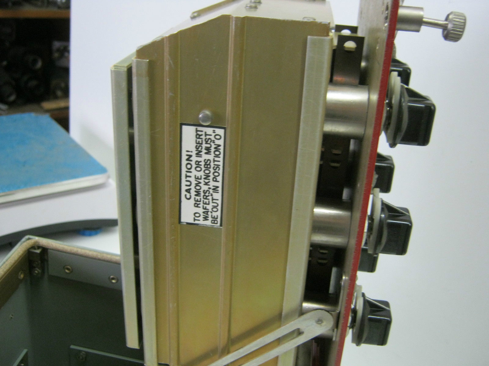
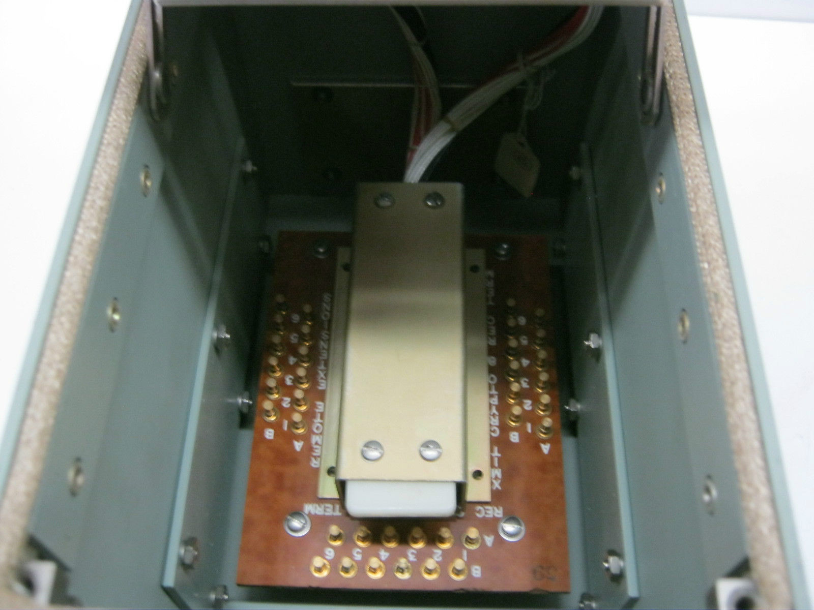
SA-1794/UG Low-level Switching Unit
|
SA-1794/UG installed aboard FFG-54
 |
SA-1794/UG Teletypewriter
Switching Unit Incorporates 6 push-pull rotary switches with instantly
removable wafers, low level gold plated contacts, wafers and receptacles,
extension capabilities for system expansion, a completely shielded
enclosure and minimum size; each unit contains six eight-position
switches, mounted in two vertical rows; the positions are six active
transfer positions, one extension position and an OFF position; switch
position indicating device indicates both the rotary position and the IN
position of the knob; when a switching matrix of more than six is desired,
additional input or output (or both) devices can be added by using the
extension position of the basic switch; systems of any size can be
assembled with the multiple use of one basic module. |
|
 |
 |
|
|
 |
 |
|
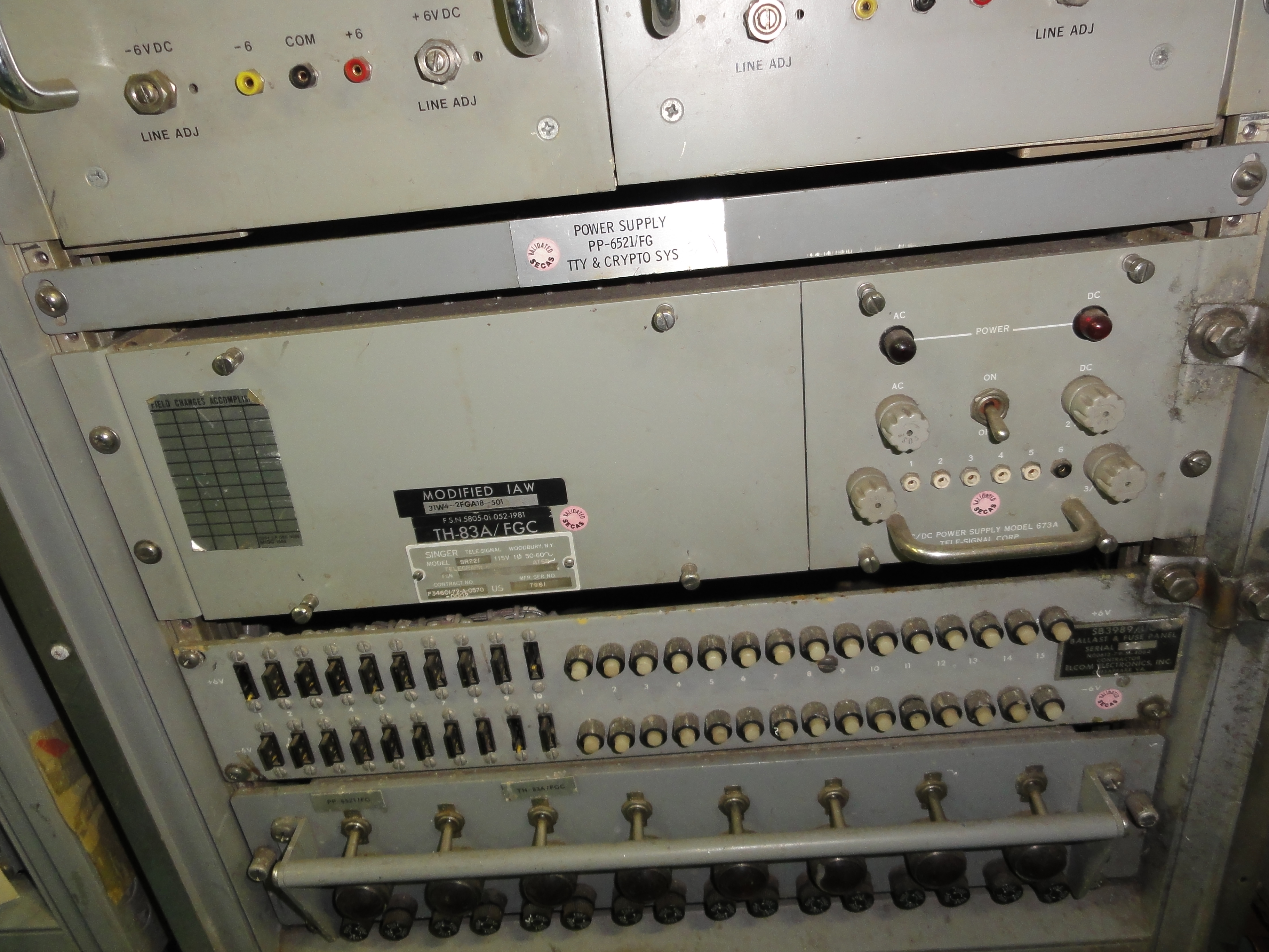
TH-83A/FGC low-level TTY hubbing repeater
|
TH-83A aboard USS Iowa
 |
 |
for +/- 6v signals
More info in NAVSHIPS 0967-391-6010
download 38 MB pdf
|
MK-1135/UG level converter
|
has six full-duplex lines converting between
high-level and low-level TTY signals
INFO and PHOTO wanted |
CV-2757/SGC level converter
|
 |
Half or full duplex converter between high-level
and low-level TTY signals
- INFO and PHOTO wanted |
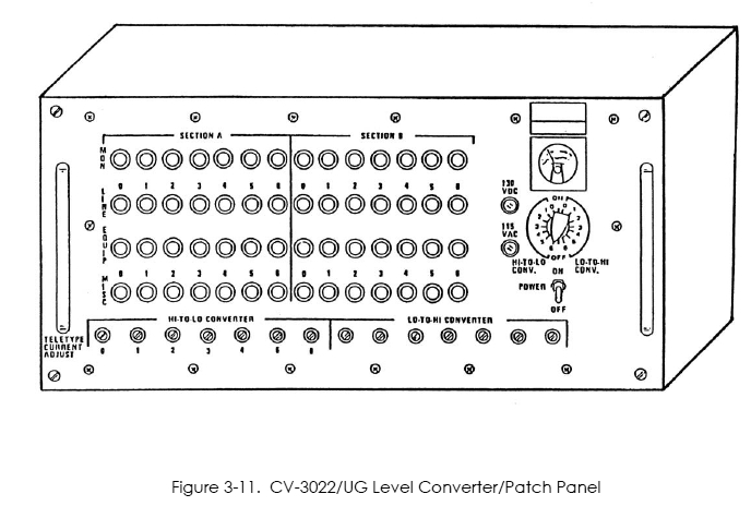
CV-3022/UG level converter
and low level patch panel
|
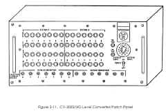 |
7 channel high-to-low conversion (120V to 6V)
7 channel low-to-high conversion (6V to 120V)
14 channel low level patch panel.
115 VAC, 60 Hz, single phase; 120 VDC 1 AMP.
18 in. long, 17.75 in. wide, 8.75 in. deep; 40 pounds, rack mounted.
Used with various shipboard teletypewriter systems and NAVMACS
|
CV-3691/UGC level converter
|
converter from high-level to low-level TTY
signal
- INFO and PHOTO wanted |
CV-3971/S interface adapter
|
full duplex converter between high-level and
low-level TTY signals
- INFO and PHOTO wanted |
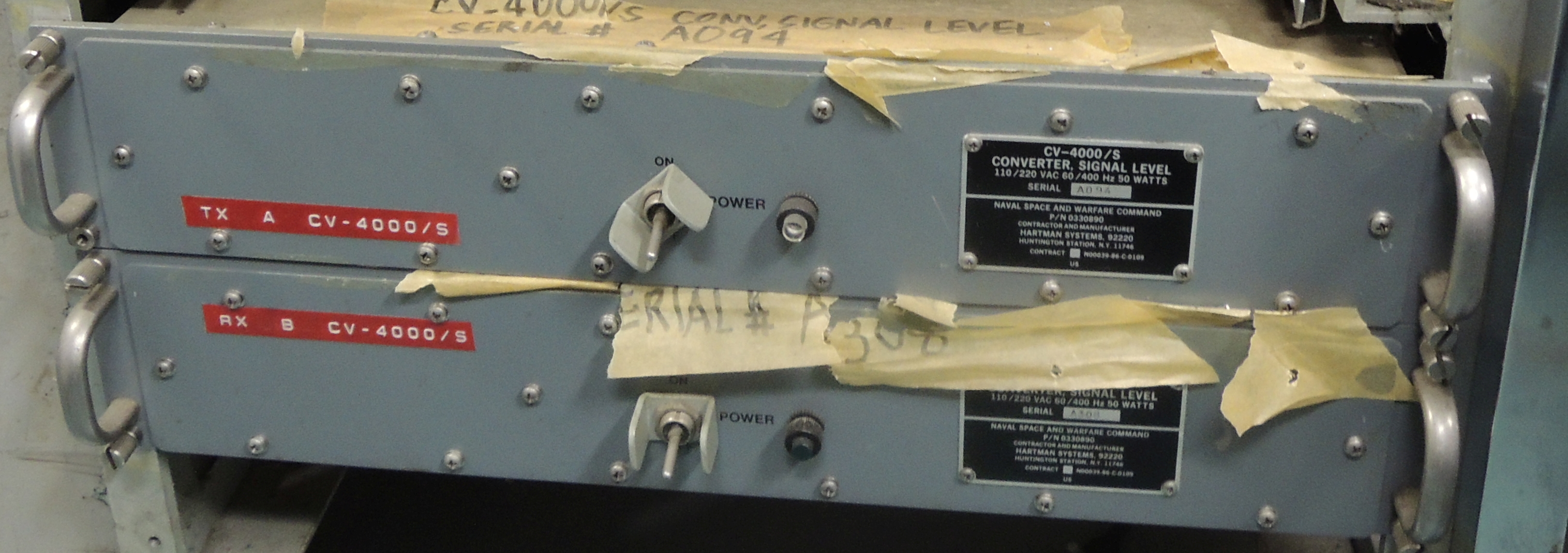
CV-4000/S level converter
|
 |
converter from high-level to low-level TTY
signal
- INFO and PHOTO wanted |
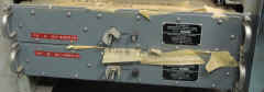
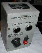
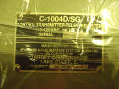
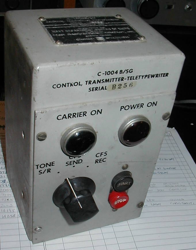
C-1004/SG
C-1004A/SG
C-1004B/SG
C-1004C/SG
|
|
|
|
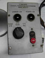
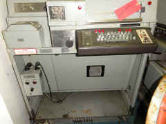
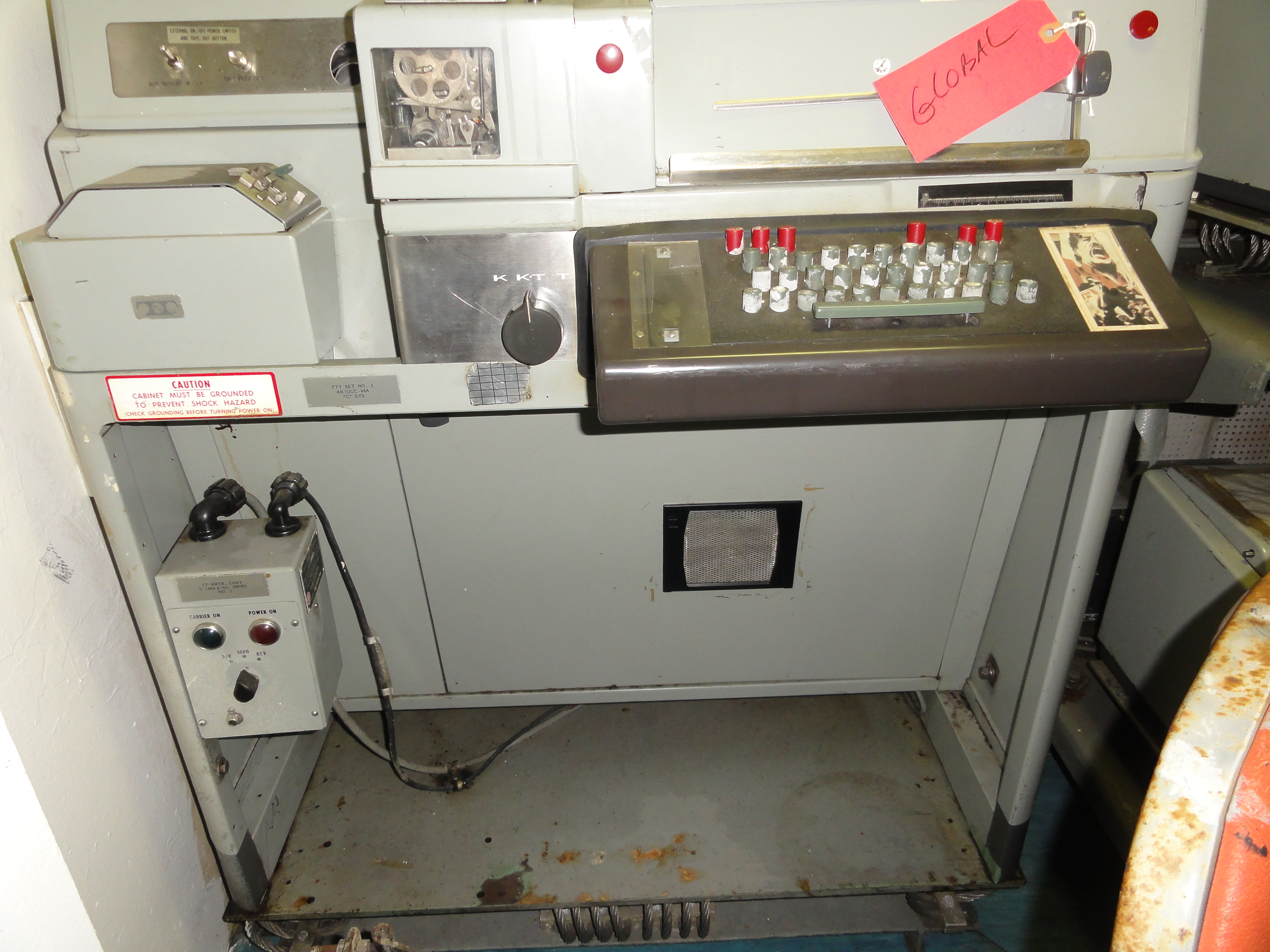
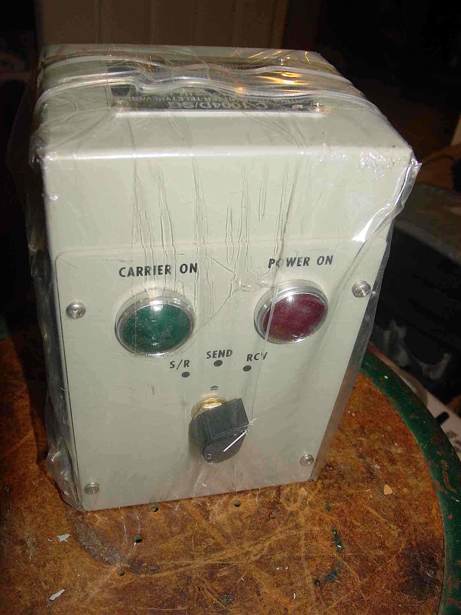
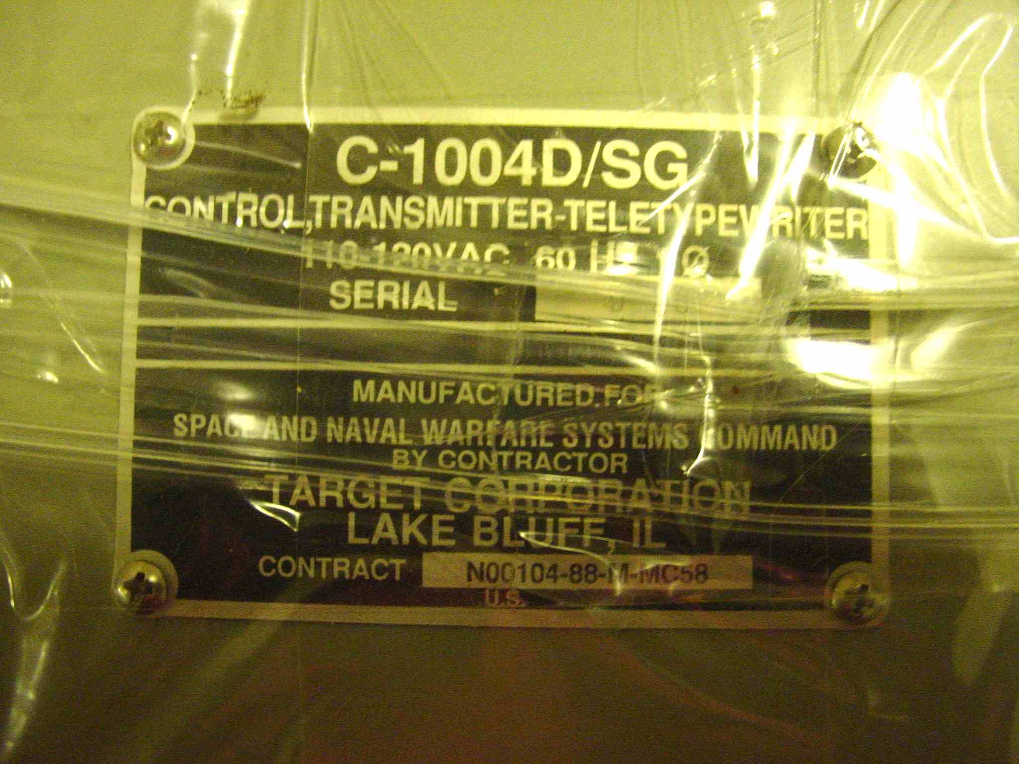
C-1004D/SG
Installed on UGC-6 teletype aboard BB-61
|
|
|
similar to C-1004
no on-off pushbutton switches
wiring diagram of C-1004D
installed aboard BB-61 - thanks to Tyler KN6JEB
|
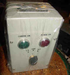
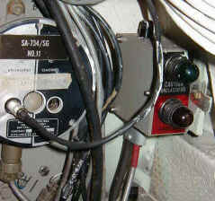
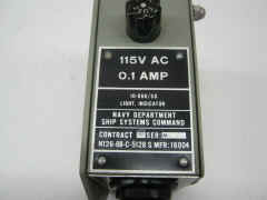
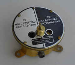
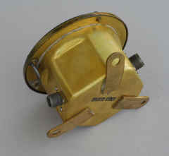
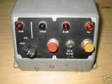
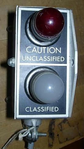
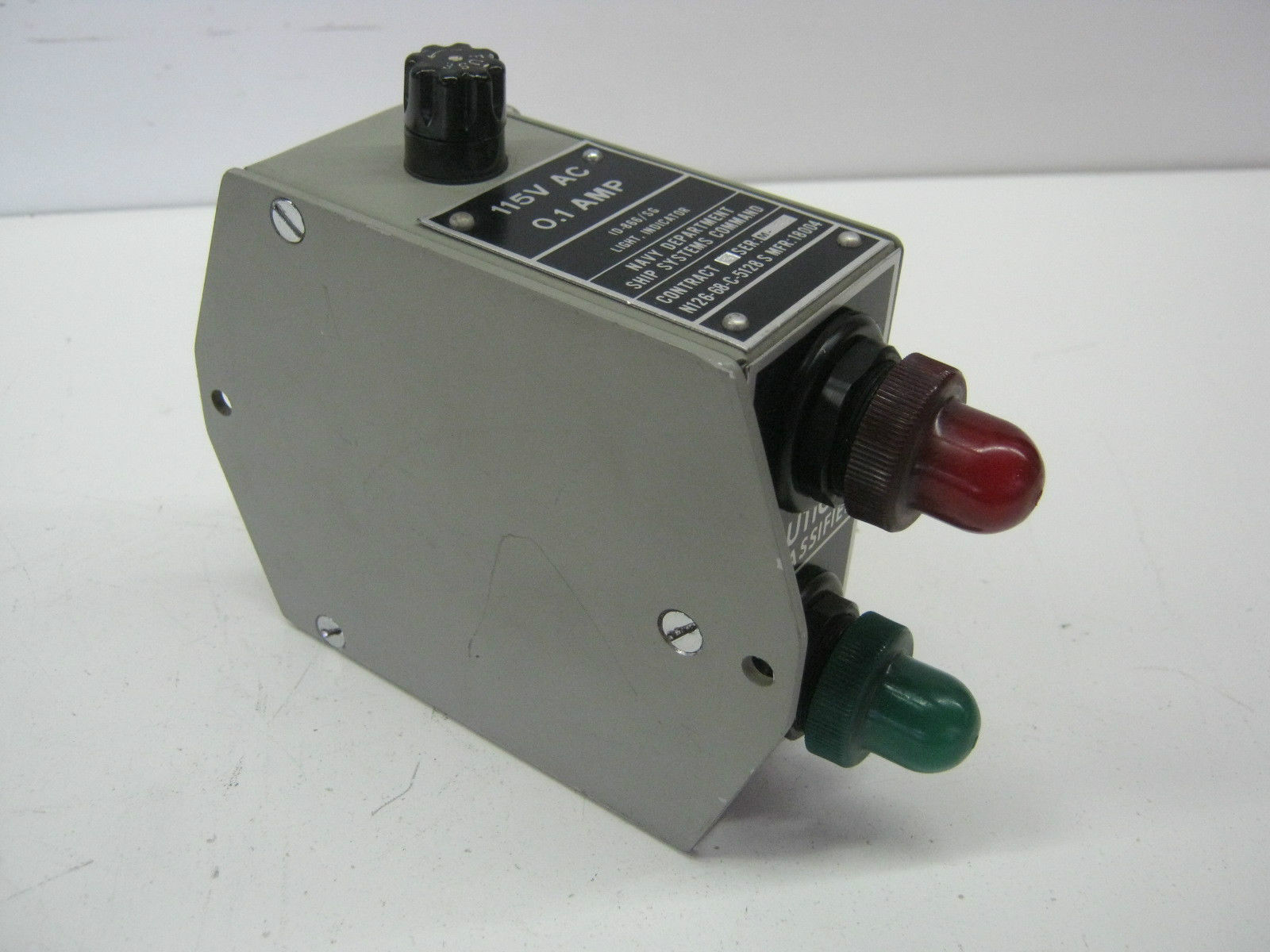
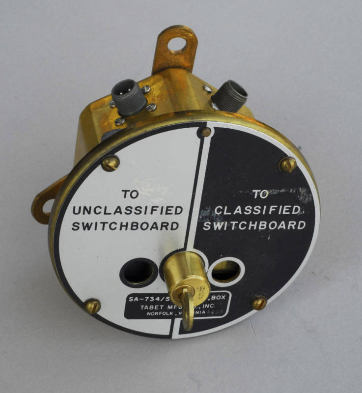
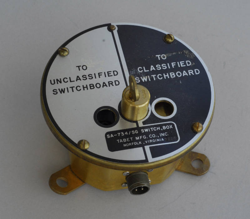
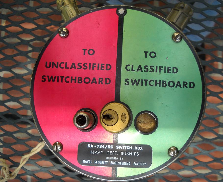
SA-734/SG Switch and ID-866/SG Indicator
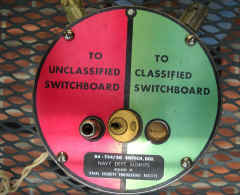
NOTE - These seem a bit confusing. RED
normally means classified circuits and BLACK means unclassified circuits.
However, the SA-734 UNCLASSIFIED switch position is RED and the ID-866
UNCLASSIFIED lamp is RED.
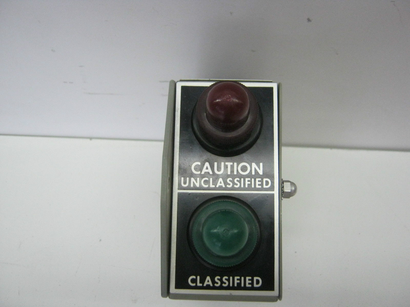
Furthermore, I have seen some ID-866 red/green
units where the CLASSIFIED indicator is RED and the CAUTION-UNCLASSIFIED
indicator is GREEN
This is incorrect - See below.
The reasoning is because these are Teletype machine connections
- if you are connected to the UNCLASSIFIED switchboard you need to be
careful typing because you will transmit in the clear. If you are
connected to the CLASSIFIED switchboard, anything you type will be
encrypted anyway. Note that some of the USS Midway switches are labeled SECURE
CIR OFF (RED) and SECURE CIR ON (BLACK), which is clearer.
AHA - Here's the spec (MIL-STD-1680C)
5.3.4.4 Lock-out switch visual indicator. The ID-866/SG Indicator
Light provides a visual indication of the setting of the SA-734/SG or SA
2371/SG Switch Box. Where the switch box is used for a sharing of
processing equipment, the indicator light shall be co-located with the
processing equipment for operator viewing. Where the switch box is used as
a RED signal line disconnect, the indicator light shall be co-located with
the switch box. Visual indicator lamps for Classified or Unclassified, or
Classified or Disconnect shall have the following color jewels installed:
-
Green jewel: Color to indicate a classified circuit,
or a circuit of higher classification.
-
Red jewel: Color to indicate an unclassified circuit,
a circuit of lower classification, or disconnect position.
I finally got a manual (NAVSHIPS 93757) - 5
MB pdf - and it confirms RED means you are connected to the
UNCLASSIFIED switchboard.
|
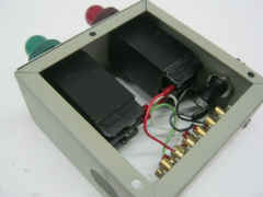
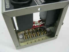
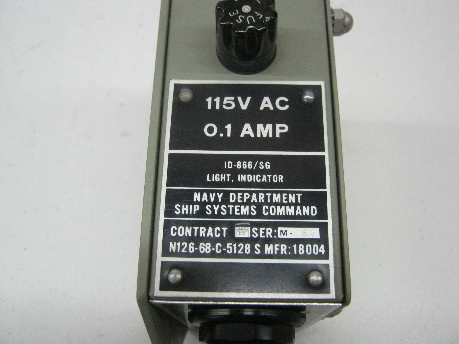
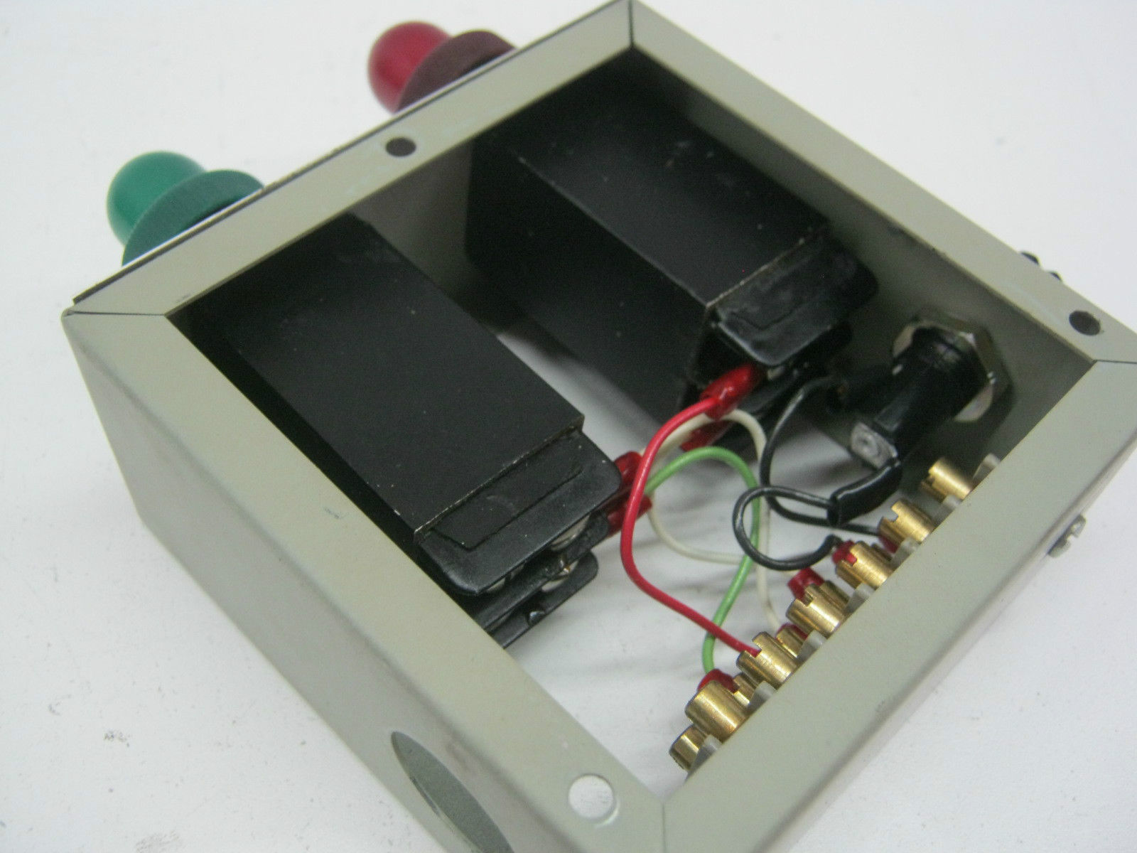
ID-866/SG
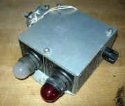
The ID-866/SG Indicator Light, when used to show the
status of a shared RED/BLACK processing equipment, shall derive primary
AC. power from the shared equipment to assure the ID-866/SG is energized
when the shared equipment is energized.
|
UNCLASSIFIED/CLASSIFIED
warning indicators with correct color scheme. 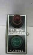
|
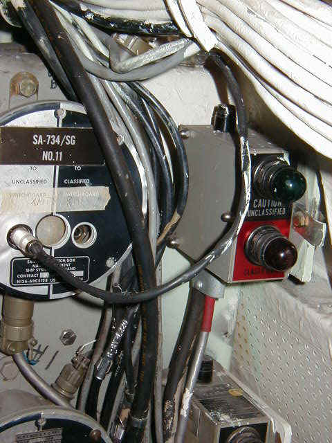
ID-866 and SA-734 aboard USS New Jersey with the WRONG ID-866 color
scheme.
|
SA-734 & ID-866 aboard USS Iowa
with the WRONG ID-866 color scheme
|
|
|
|
|
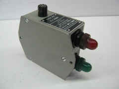
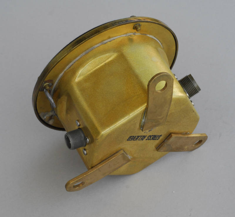
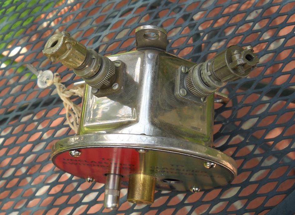
SA-734/SG
|
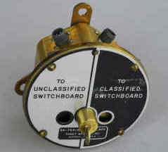
|
TTY switch - key lockout of plug and connections
|
|
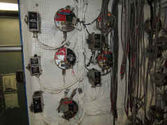
ID-866 and SA-734 aboard USS Midway
|
|
|
|
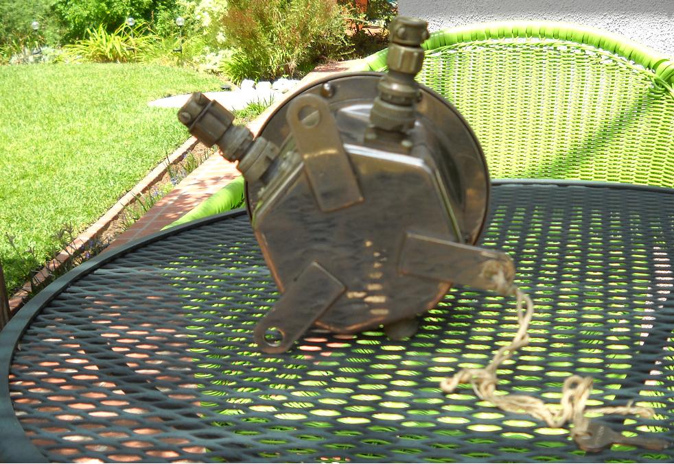
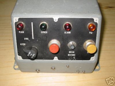
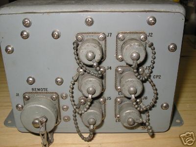
TSEC/KWX-7
|
photos from ebay via Jerry Proc
|
|
- sync control switch for KW-7
crypto unit
|


